L&L TLR04M-350-700 User manual
1/8
L&L Luce&Light srl / Via Trescalini, 5 / 36031 Dueville, Vicenza / Italy / T +39 0444 36 05 71 / F +39 0444 59 43 04
TLR04M-350-700
+DAECTLR04M-350-700
rev. 02 30/11/2022
B10
Made in Italy
Power supply units and control gear /Alimentatori ed elettronica di controllo
IP20
12 ÷ 36 Vdc - 433.92 MHz
TLR04M-350-700
CONTROL UNIT FOR RGB LED FIXTURES IN COSTANT CURRENT 350-700 mA (JUMPER SETTING).
POWER SUPPLY IN 12-36VDC. RX RADIO 433.920 MHz, 3 PUSH N.O. INPUTS, EXTENDER CONNECTOR AVAILABLE.
TECHNICAL DATA
Power supply 12-36 Vdc
Output 3 channels (@ 350/700 mA)
Type of load RGB LED with constant current
N° of programmable transmitters 30
Radio frequency 433.920MHz ISM
IP rate IP20
Working temperature -20°C — +55°C
Dimensions 174x46x35 mm
WARNINGS
• Installation must be carried out only by qualied technicians in compliance with the electrical and safetystandards in force.
• All connections must be made with the power turned o.
• Use suitable cables.
• Do not cut through the aerial.
• A suitably sized disconnection device must be set up on the electric power line that supplies the product.
• Disposal of waste materials must fully respect local standards.
INSTALLATION INSTRUCTIONS TLR04M-350-700
2/8
L&L Luce&Light srl / Via Trescalini, 5 / 36031 Dueville, Vicenza / Italy / T +39 0444 36 05 71 / F +39 0444 59 43 04
TLR04M-350-700
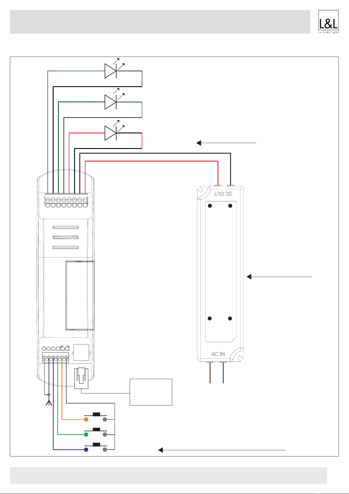
INPUT3: P3
INPUT2: P2
INPUT1: P1
LN
L: Brown
N: Blue
+Red
- Black
POWER SUPPLY
OUTPUT: 12V/24V/36V
+
P1
P2
P3
C
-+-+--+
BGR
7891011121314
123456
CONNECTION DIAGRAM
Loads with constant
current
(choose a load that’s
compatible with the
power supply in terms
of power).
12 to 36 Vdc
power supply
(choose a power supply
compatible with the load
to be controlled in terms
of voltage and power).
! =
Terminals 3-4-5 are reserved for devices with
buttons (see page 4 for operation).
INSTALLATION INSTRUCTIONS TLR04M-350-700
EXTENDER
(accessory
module)
OUT3
BLUE LED
AERIAL AERIAL
POWER SUPPLY
OUT2
GREEN LED
OUT1
RED LED
Note: multiple buttons or loads can be connected by using parallel cabling.

3/8
L&L Luce&Light srl / Via Trescalini, 5 / 36031 Dueville, Vicenza / Italy / T +39 0444 36 05 71 / F +39 0444 59 43 04
TLR04M-350-700
OUT1OUT2OUT3
SET THE OUTPUT CURRENT
With the jumper is possible to set the current provided to the Leds.
The selection is dierent for each out:
JUMPER INSERTED=
700mA
JUMPER NOT INSERTED=
350mA
INSTALLATION INSTRUCTIONS TLR04M-350-700
4/8
L&L Luce&Light srl / Via Trescalini, 5 / 36031 Dueville, Vicenza / Italy / T +39 0444 36 05 71 / F +39 0444 59 43 04
TLR04M-350-700
PUSH N.O. USAGE
FIXTURES
OFF
FIXTURES
ON
INPUT P1:
short pressure On O
INPUT P1:
long pressure Dimmer up Dimmer up / Dimmer down
INPUT P2:
short pressure no actions
Color change refered to a memorized palette (white, light
yellow, light green, dark green, light blue, blue, violet, light
violet, pink, red, orange, light orange, yellow)
INPUT P2:
long pressure Color dene: choose of the color viewing all gamma of RGB Memorization of the state at the desired setup
INPUT P3:
short pressure no actions
Play / stop “color cycle”
Every short press:
1 ash= play “color cycle”
2 ashes= stop “color cycle”
INPUT P3:
long pressure no actions
Setup “color cycle” duration
Every long press:
1 ash= “color cycle” of 90 sec
2 ashes= “color cycle” of 15 min
INSTALLATION INSTRUCTIONS TLR04M-350-700

5/8
L&L Luce&Light srl / Via Trescalini, 5 / 36031 Dueville, Vicenza / Italy / T +39 0444 36 05 71 / F +39 0444 59 43 04
TLR04M-350-700
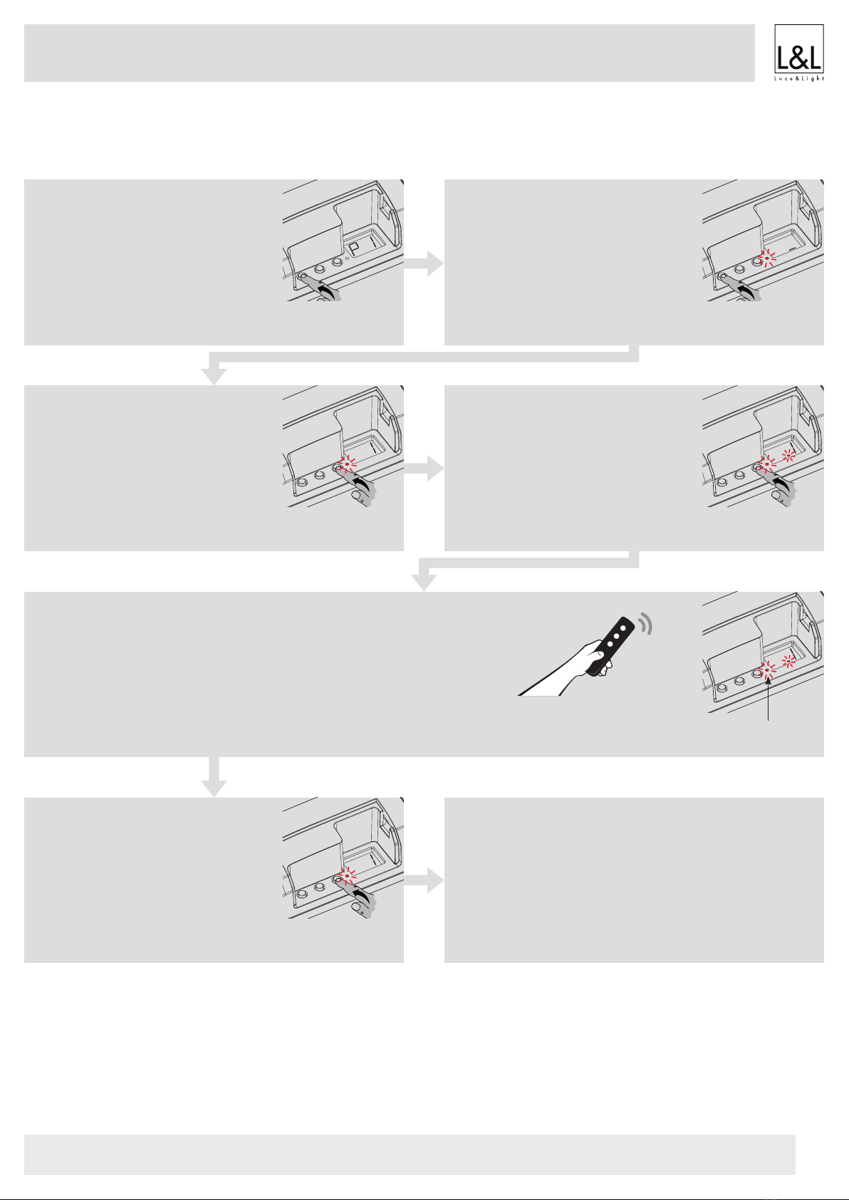
RADIO PROGRAMMING
PROCEDURE:
STEP 1
Short press on the “SET” key let you
scroll through the menu until “P1” pro-
gramming appears on the display.
SHORT
PRESSURE
STEP 2
A prolonged press on the “SET” key
(approx. 3 seconds) takes you into pro-
gramming.
The LED on the receiver comes on.
LONG
PRESSURE
STEP 3
Short press on key “B” let you set value
“1” on the display.
SHORT
PRESSURE
STEP 4
Give a long press on key “B” (approx.
3 seconds).
The LED on the display comes on.
LONG
PRESSURE
STEP 5
Make a transmission with the transmitter to be saved (see trans-
mitter manual, the paragraph entitled “transmitter programming”).
The LED on the receiver ashes 3 times to signal that it has been
received.
MAKE A TRANSMISSION
WITH THE TRANSMITTER
THE LED
FLASHES 3 TIMES
STEP 6
The control unit listens for 50 seconds
in case you want to add other transmit-
ters.
To immediately exit the procedure give
a short pressure on key “b”.
The LED on the display turns o.
SHORT
PRESSURE
STEP 7
The control unit goes back to the menu displaying the radio pro-
gramming. If you want to save other transmitters, go back to
point 3 of this procedure.
If you want to go back to the menu displaying the dierent types
of programming, give a prolonged press to the “SET” key (ap-
prox. 3 seconds).
INSTALLATION INSTRUCTIONS TLR04M-350-700

6/8
L&L Luce&Light srl / Via Trescalini, 5 / 36031 Dueville, Vicenza / Italy / T +39 0444 36 05 71 / F +39 0444 59 43 04
TLR04M-350-700
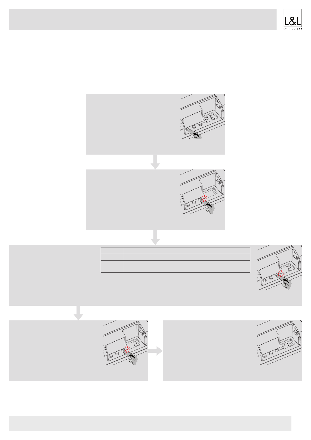
LOAD STATE WHEN THE CONTROL UNIT IS SWITCHED ON
Default: Light O
This process is used to set the state of Leds when the control unit is switched on (for example when the power supply is provided by a general
switch or timer).
PROCEDURE:
STEP 1
Short press on the “SET” key let you
scroll through the menu until “P6” pro-
gramming appears on the display.
SHORT
PRESSURE
STEP 2
A prolonged press on the “SET” key
(approx. 3 seconds) takes you into pro-
gramming.
The LED on the receiver lights up.
LONG
PRESSURE
STEP 3
Short press on key “B” let you choose
the function you want to program
shown on the displays based on what
is shown in the table alongside.
DISPLAY BRIGHTNESS AT SWITCH-ON
1 Default (light o)
2 The light switches on in the same status as the load is cur-
rently in: set the desired status of light.
SHORT
PRESSURE
STEP 4
To conrm give a prolonged press on
the “SET” key (approx. 3 seconds).
LONG
PRESSURE
STEP 5
The control unit goes back to the menu
displaying the dierent types of pro-
gramming.
INSTALLATION INSTRUCTIONS TLR04M-350-700

7/8
L&L Luce&Light srl / Via Trescalini, 5 / 36031 Dueville, Vicenza / Italy / T +39 0444 36 05 71 / F +39 0444 59 43 04
TLR04M-350-700
FACTORY SETTING, RESET
This procedure let you take the control unit back to factory settings.
PROCEDURE:
STEP 1
Short press on the “SET” key let you
scroll through the menu until “FS” pro-
gramming appears on the display.
SHORT
PRESSURE
STEP 2
A prolonged press on the “SET” key
(approx. 3 seconds) takes you into pro-
gramming.
The LED on the receiver lights up.
LONG
PRESSURE
STEP 3
Short press on the “B” key, let you modify the setup that appears in display “b”:
display = F1 reset factory parameters, but no deletion of already programmed transmitters;
display = F2 full reset of factory parameters, even stored transmitters will be deleted.
SHORT
PRESSURE
STEP 4
To conrm, give a prolonged press on
the “SET” key (approx. 3 seconds).
The LED ashes.
LONG
PRESSURE
STEP 5
The control unit goes back to the menu
displaying the dierent types of pro-
gramming.
INSTALLATION INSTRUCTIONS TLR04M-350-700


1/8
L&L Luce&Light srl / Via Trescalini, 5 / 36031 Dueville, Vicenza / Italy / T +39 0444 36 05 71 / F +39 0444 59 43 04
TLR04M-350-700
+DAECTLR04M-350-700
rev. 02 30/11/2022
B10
Made in Italy
Power supply units and control gear /Alimentatori ed elettronica di controllo
IP20
12 ÷ 36 Vdc - 433.92 MHz
ISTRUZIONI DI INSTALLAZIONE TLR04M 350-700
TLR04M-350-700
CENTRALE DI COMANDO PER LED RGB IN CORRENTE COSTANTE 350-700 mA (JUMPER SU OGNI USCITA).
ALIMENTAZIONE 12-36Vdc. RX RADIO 433.920 MHz, 3 INGRESSI FILARI, INGRESSO PER EXTENDER.
DATI TECNICI
Alimentazione 12-36 Vdc
Uscita 3 canali (@350/700mA)
Tipo di carico LED RGB in corrente costante
N° trasmettitori programmabili 30
Frequanza radio 433.920MHz ISM
Grado di protezione IP20
Temperatura di funzionamento -20°C ÷ +55°C
Dimensioni 174x46x35 mm
AVVERTENZE
• L’installazione deve essere eseguita esclusivamente da personale tecnico qualicato nel rispetto delle normative elettriche e delle norme
di sicurezza vigenti.
• Tutti i collegamenti devono essere eseguiti in assenza di tensione elettrica.
• Servirsi di cavi adeguati.
• Non tagliare l’antenna (vedi gura 1.1b).
• Prevedere, nella linea elettrica che alimenta il prodotto, un dispositivo di disconnessione opportunamente dimensionato.
• Smaltire i materiali di riuto nel pieno rispetto della normativa locale.
• Non superare i limiti di carico indicati e utilizzare alimentatori correttamente dimensionati con il carico e protetti.

2/8
L&L Luce&Light srl / Via Trescalini, 5 / 36031 Dueville, Vicenza / Italy / T +39 0444 36 05 71 / F +39 0444 59 43 04
TLR04M-350-700
INPUT3: P3
INPUT2: P2
INPUT1: P1
LN
L: Brown
N: Blue
+Red
- Black
POWER SUPPLY
OUTPUT: 12V/24V/36V
+
P1
P2
P3
C
-+-+--+
BGR
7891011121314
123456
ISTRUZIONI DI INSTALLAZIONE TLR04M-350-700
SCHEMA DI COLLEGAMENTO
Carichi a corrente
costante
(scegliere un il carico
compatibile con l’ali-
mentatore in termini di
tensione e potenza).
Alimentatore
da 12 a 36 Vdc
(scegliere un alimentato-
re compatibile con il cari-
co da pilotare in termini di
tensione e potenza).
! =
I morsetti 3-4-5 sono dedicati a dispositivi di
tipo pulsante (vedi pag 4 per il funzionamento).
EXTENDER
(modulo
accessorio)
OUT3
LED BLU
ANTENNA ANTENNA
ALIMENTAZIONE
OUT2
LED VERDE
OUT1
LED ROSSO
ATTENZIONE: si possono collegare più pulsanti o carichi cablandoli in parallelo.

3/8
L&L Luce&Light srl / Via Trescalini, 5 / 36031 Dueville, Vicenza / Italy / T +39 0444 36 05 71 / F +39 0444 59 43 04
TLR04M-350-700
OUT1OUT2OUT3
ISTRUZIONI DI INSTALLAZIONE TLR04M-350-700
SELEZIONE DELLA CORRENTE IN USCITA
Con i jumper in scheda è possibile selezionare la corrente con la quale la centrale alimenta il carico.
La selezione può essere fatta per ogni uscita separatamente:
JUMPER INSERITO=
700mA
JUMPER NON INSERITO=
350mA

4/8
L&L Luce&Light srl / Via Trescalini, 5 / 36031 Dueville, Vicenza / Italy / T +39 0444 36 05 71 / F +39 0444 59 43 04
TLR04M-350-700
ISTRUZIONI DI INSTALLAZIONE TLR04M-350-700
UTILIZZO VIA INPUT PULSANTE NA
CARICO
SPENTO
CARICO
ACCESO
INGRESSO P1:
pressione breve On del carico O del carico
INGRESSO P1:
pressione lunga Dimmer up intensità Dimmer up intensità / Dimmer down intensità
INGRESSO P2:
pressione breve Nessuna azione
Cambio del colore (bianco, giallo chiaro, verde chiaro, ver-
de scuro, azzurro, blu, viola, viola chiaro, rosa, rosso, aran-
cione, arancione chiaro, giallo)
INGRESSO P2:
pressione lunga
Dimmer colore: mi muovo gradatamente tra tutti i colori, al
rilascio del tasto il carico si ferma sul colore visualizzato Memorizzo il colore e l’intensità su cui è impostato il carico
INGRESSO P3:
pressione breve Nessuna azione
Play / stop “ciclo colore”
Ad ogni pressione prolungata del tasto il carico emetterà:
1 lampeggio= play “ciclo colore”
2 lampeggi= stop “ciclo colore”
INGRESSO P3:
pressione lunga Nessuna azione
Regolazione durata “ciclo colore”
Ad ogni pressione prolungata del tasto il carico emetterà:
1 lampeggio= “ciclo colore” di 90 secondi
2 lampeggi= “ciclo colore” di 15 minuti
5/8
L&L Luce&Light srl / Via Trescalini, 5 / 36031 Dueville, Vicenza / Italy / T +39 0444 36 05 71 / F +39 0444 59 43 04
TLR04M-350-700
PROGRAMMAZIONE RADIO
PROCEDURA:
ISTRUZIONI DI INSTALLAZIONE TLR04M-350-700
PASSO 1
Con pressioni brevi del tasto “SET”
scorrere il menù no a visualizzare sul
display la programmazione “P1”.
PRESSIONE
BREVE
PASSO 2
Fare una pressione prolungata del ta-
sto “SET” (circa 3s) per entrare nella
programmazione.
Il led sulla ricevente si accende.
PRESSIONE
LUNGA
PASSO 3
Con pressioni brevi del tasto “B” impo-
stare il valore “1” sul display.
PRESSIONE
BREVE
PASSO 4
Fare una pressione prolungata del ta-
sto “B” (circa 3s).
Il led sul display si accende.
PRESSIONE
LUNGA
PASSO 5
Fare una trasmissione con il trasmettitore da memorizzare (vedi
manuale del trasmettitore, paragrafo “programmazione del tra-
smettitore”).
Il led sulla ricevente emette tre lampeggi e si riaccende sso.
INVIO DI UN COMANDO
CON IL TRASMETTITORE
LED FA
3 LAMPEGGI
PASSO 6
La centrale resta in ascolto per 50 se-
condi.
Per uscire immediatamente dalla pro-
cedura fare una pressione breve del
tasto “b”.
Il led sul display si spegne.
PRESSIONE
BREVE
PASSO 7
Nel display si torna al menu di “programmazione radio”.
Se si vogliono memorizzare altri trasmettitori, ritornare al punto 3
di questa procedura.
Se si vuole tornare al menù di visualizzazione delle programma-
zioni fare una pressione prolungata (circa 3 sec) del tasto “SET”.
6/8
L&L Luce&Light srl / Via Trescalini, 5 / 36031 Dueville, Vicenza / Italy / T +39 0444 36 05 71 / F +39 0444 59 43 04
TLR04M-350-700
ISTRUZIONI DI INSTALLAZIONE TLR04M-350-700
STATO DELLA LUCE ALL’ALIMENTAZIONE DELLA CENTRALE
Default: Luce spenta
Con questa procedura si imposta lo stato della luce quando la centralina viene alimentata (utile ad esempio se la centrale è alimentata da un
interruttore generale o da un orologio a monte).
PROCEDURA:
PASSO 1
Con pressioni brevi del tasto “SET”
scorrere il menù no a visualizzare sul
display la programmazione “P6”.
PRESSIONE
BREVE
PASSO 2
Fare una pressione prolungata del ta-
sto “SET” (circa 3s) per entrare nella
programmazione.
Il led sulla ricevente si accende.
PRESSIONE
LUNGA
PASSO 3
Con pressioni brevi del tasto “B” sce-
gliere la funzione che si vuole program-
mare visualizzata sul display in base
alle indicazioni della tabella a lato.
DISPLAY LUMINOSITÀ ALL’ACCENSIONE
1 Default (luce spenta)
2 Accensione della luce pari allo stato in cui si trova il carico
attualmente: impostare la luce desiderata.
PRESSIONE
BREVE
PASSO 4
Per confermare fare una pressione pro-
lungata del tasto “SET” (circa 3s).
PRESSIONE
LUNGA
PASSO 5
Nel display si torna al menu di “visualiz-
zazione delle programmazioni”.

7/8
L&L Luce&Light srl / Via Trescalini, 5 / 36031 Dueville, Vicenza / Italy / T +39 0444 36 05 71 / F +39 0444 59 43 04
TLR04M-350-700
ISTRUZIONI DI INSTALLAZIONE TLR04M-350-700
IMPOSTAZIONI DI FABBRICA, RESET DELLA CENTRALE
Con questa procedura è possibile portare la centrale alle impostazioni di fabbrica.
PROCEDURA:
PASSO 1
Con pressioni brevi del tasto “SET”
scorrere il menù no a visualizzare sul
display la programmazione “FS”.
PRESSIONE
BREVE
PASSO 2
Fare una pressione prolungata del ta-
sto “SET” (circa 3s) per entrare nella
programmazione.
Il led sulla ricevente si accende.
PRESSIONE
LUNGA
PASSO 3
Con pressioni brevi del tasto “B” posso modicare l’impostazione visualizzata sul display “b”:
display = F1 reset ai parametri di fabbrica, ma nessuna cancellazione dei trasmettitori già programmati;
display = F2 reset completo ai parametri di fabbrica, anche i trasmettitori memorizzati saranno cancellati.
PRESSIONE
BREVE
PASSO 4
Per confermare fare una pressione pro-
lungata del tasto “SET” (circa 3s).
Il led fa dei lampeggi.
PRESSIONE
LUNGA
PASSO 5
Nel display si torna al menu di “visualiz-
zazione delle programmazioni”.

Table of contents
Languages:
Other L&L Control Unit manuals


