KAYA Komodo CoaXPress User manual

Komodo CoaXPress Frame Grabber
Hardware Reference and Installation
Guide
(Part-No. KY-FGK-XXX)
5201anuaryJ
20 aMesila St., Nesher 368852 0, Israel
POB 25004, Haifa 3125001, Israel
Tel:(+972)-72-2723500 Fax:(+972)-72-2723511
www.kayainstruments.com

Komodo Frame Grabber User Guide
1
Figures and Tables ..................................................................................................2
Introduction............................................................................................................. 3
Safety Precautions ...................................................................................... 3
Disclaimer................................................................................................... 4
Key Features............................................................................................................ 6
3.1 Overview.................................................................................................6
3.2 Features...................................................................................................6
3.3 Product Applications ...............................................................................7
3.4 Related documents and accessories..........................................................8
System Description ................................................................................................. 9
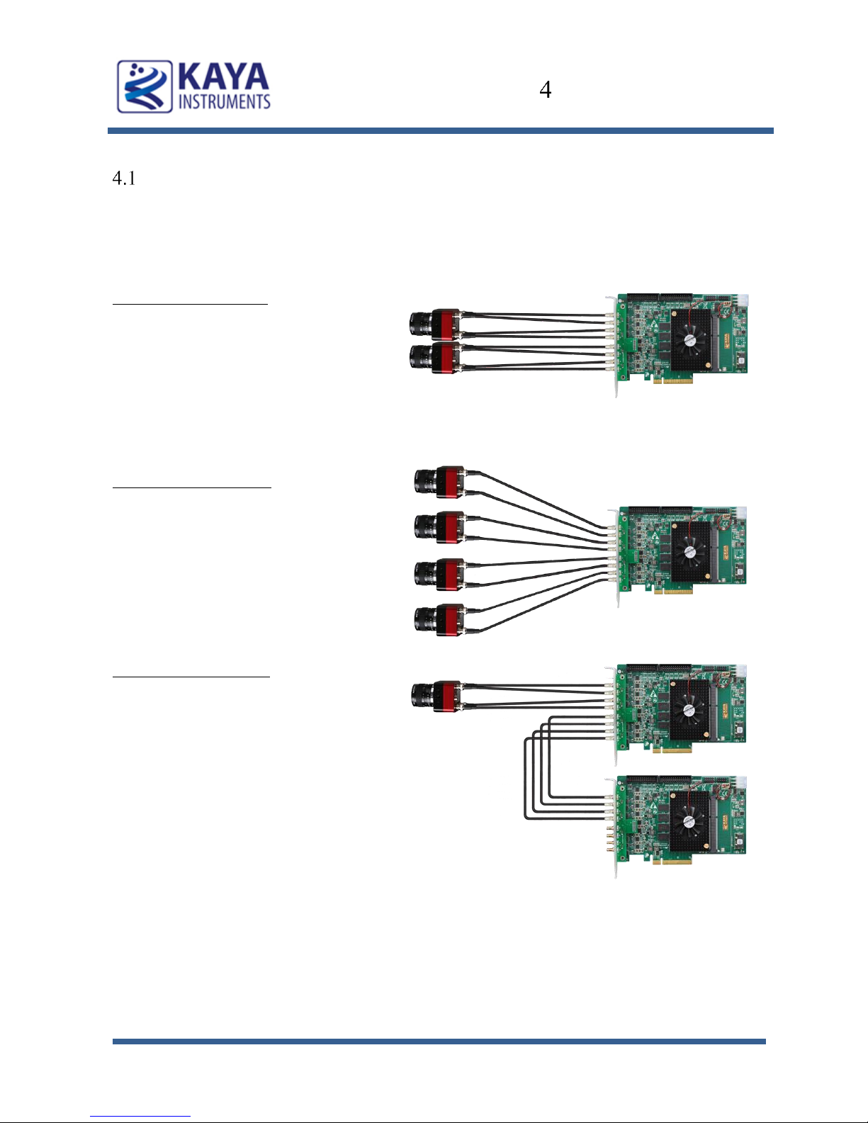
4.1 Example System Block Diagram..............................................................9
4.2 External View of the Board......................................................................10
Mechanical Specifications ...................................................................................... 11
5.1 Essentials to get started............................................................................11
5.2 Power supplies.........................................................................................11
5.3 Absolute maximum ratings......................................................................12
5.4 Mechanical dimensions............................................................................13
Installation and Configurations............................................................................... 14
6.1 Installation instructions............................................................................14
6.2 Connecting to CoaXPress output connectors............................................14
6.3 Komodo LEDs.........................................................................................15
6.4 Komodo Hardware Reference..................................................................16
6.5 Komodo Board Block Diagram................................................................17
6.6 Video stream acquisition..........................................................................18
6.7 Auxiliary Input/Output signals.................................................................18
6.8 Absolute maximum ratings for GPIO.......................................................25
Contents

Komodo Frame Grabber User Guide
2
Figures
FIGURE 1:COAXPRESS SYSTEM BLOCK DIAGRAM ................................................................................9
FIGURE 2: KOMODO BOARD EXTERNAL VIEW......................................................................................10
FIGURE 3:EXTERNAL POWER SUPPLY CONNECTOR.............................................................................12
FIGURE 4: PCB MECHANICAL DIMENSIONS........................................................................................13
FIGURE 5: KOMODO BOARD LED’S LOCATIONS .................................................................................16
FIGURE 6: KOMODO BOARD BLOCK DIAGRAM ...................................................................................17
FIGURE 7: GPIO CONNECTORS LOCATION...........................................................................................19
FIGURE 8: IO’S SCHEMATIC.................................................................................................................24
Tables
TABLE 1: ABSOLUTE MAXIMUM RATINGS ...........................................................................................12
TABLE 2: COAXPRESS LINKS STATUS LED’S......................................................................................15
TABLE 3: BOARD STATUS LED’S........................................................................................................16
TABLE 4: J1 CONNECTOR PINOUT ........................................................................................................20
TABLE 5: J2 CONNECTOR PINOUT ........................................................................................................21
TABLE 6: LVDS OUTPUT DC SPECIFICATIONS (DRIVER OUTPUTS)....................................................22
TABLE 7: LVDS INPUT DC SPECIFICATIONS (RECEIVER INPUTS).......................................................22
TABLE 8: LVTTL INPUT SPECIFICATIONS............................................................................................23
TABLE 9: LVTTL OUTPUT SPECIFICATIONS ........................................................................................23
TABLE 10: TTL INPUT SPECIFICATIONS...............................................................................................23
TABLE 11: TTL OUTPUT SPECIFICATIONS............................................................................................23
TABLE 12: ABSOLUTE MAXIMUM RATINGS FOR GPIO ........................................................................25
Revision History
Version
Date
Notes
0.1
Initial Release
0.2
15/2/15
Corrected Table 4 and Figure 8
Figures and Tables

Komodo Frame Grabber User Guide
3
Safety Precautions
With your Komodo CoaXPress Frame Grabber board in hand, please take a minute to
read carefully the precautions listed below in order to prevent unnecessary injuries to you
or other personnel or cause damage to property.
Before using the product, read these safety precautions carefully to assure correct
use.
These precautions contain serious safety instructions that must be observed.
After reading through this manual, be sure to act upon it to prevent misuse of
product.
Caution
In the event of a failure, disconnect the power supply.
If the product is used as is, a fire or electric shock may occur. Disconnect the power supply
immediately and contact our sales personnel for repair.
If an unpleasant smell or smoking occurs, disconnect the power supply.
If the product is used as is, a fire or electric shock may occur. Disconnect the power supply
immediately. After verifying that no smoking is observed, contact our sales personnel for repair.
Do not disassemble, repair or modify the product.
Otherwise, a fire or electric shock may occur due to a short circuit or heat generation. For
inspection, modification or repair, contact our sales personnel.
Do not touch a cooling fan.
As a cooling fan rotates in high speed, do not put your hand close to it. Otherwise, it may cause
injury to persons. Never touch a rotating cooling fan.
Do not place the product on unstable locations.
Otherwise, it may drop or fall, resulting in injury to persons or failure.
If the product is dropped or damaged, do not use it as is.
Otherwise, a fire or electric shock may occur.
Do not touch the product with a metallic object.
Otherwise, a fire or electric shock may occur.
Do not place the product in dusty or humid locations or where water may splash.
Otherwise, a fire or electric shock may occur.
Do not get the product wet or touch it with a wet hand.
Otherwise, the product may break down or it may cause a fire, smoking or electric shock.
Do not touch a connector on the product (gold-plated portion).
Otherwise, the surface of a connector may be contaminated with sweat or skin oil, resulting in
contact failure of a connector or it may cause a malfunction, fire or electric shock due to static
electricity.
Introduction

Komodo Frame Grabber User Guide
4
Do not use or place the product in the following locations.
● Humid and dusty locations
● Airless locations such as closet or bookshelf
● Locations which receive oily smoke or steam
● Locations close to heating equipment
● Closed inside of a car where the temperature becomes high
● Static electricity replete locations
● Locations close to water or chemicals
Otherwise, a fire, electric shock, accident or deformation may occur due to a short circuit or heat
generation.
Do not place heavy things on the product.
Otherwise, the product may be damaged.
Be sure to drain static electricity from body before you touch any electronics component
The electronic circuits in your computer and the circuits on Komodo board are sensitive to static
electricity and surges. Improper handling can seriously damage the circuits. In addition, do not
let your clothing come in contact with the circuit boards or components.
Otherwise, the product may be damaged.
Disclaimer
This product should be used for interfacing of CoaXPress camera and acquiring of
CoaXPress video streams. KAYA Instruments assumes no responsibility for any damages
resulting from the use of this product for purposes other than those stated.
Even if the product is used properly, KAYA Instruments assumes no responsibility for any
damages caused by the following:
- Earthquake, thunder, natural disaster or fire resulting from the use beyond our
responsibility, acts caused by a third party or other accidents, the customer’s willful or
accidental misuse or use under other abnormal conditions.
- Secondary impact arising from use of this product or its unusable state (business
interruption or others).
- Use of this product against the instructions given in this manual or malfunctions due to
connection to other devices.
Introduction

Komodo Frame Grabber User Guide
5
KAYA Instruments assumes no responsibility or liability for:
- Erasure or corruption of data arising from use of this product.
- Any consequences or other abnormalities arising from use of this product, or damage of
this product not due to our responsibility or failure due to modification.
Repair of this product is carried out by replacing it on a chargeable basis, not repairing the
faulty devices. However, non-chargeable replacement is offered for initial failure if such
notification is received within two weeks after delivery of the product.
Introduction

Komodo Frame Grabber User Guide
6
Overview
Komodo is best in its class Frame Grabber supporting CoaXPress standard. The Komodo
is capable of receiving video streams from up to 8 CoaXPress links in single, dual, quad or
octal modes. It is used for simultaneous capture from up to two quad link cameras. Each
link supports standard CoaXPress bitrates up to 6.25 Gbps. This CoaXPress Frame
Grabber is ideally suited for industrial, defense and aerospace Machine Vision Systems
and applications. The Komodo can easily receive video streams on the CoaXPress links
and transmit them to computer memory through the PCIe interface. This product also
provides GPIO for machine control signals, such as triggers, shaft encoders, exposure
control and general I/O, which can be control aside video stream acquisition.
The Komodo uses standard DIN connectors as a CoaXPress interface to the camera and
standard 100 mil headers for general purpose I/O. The Frame Grabber utilizes PCIe Gen3
x8 links for communication with Host PC for video uploading and configuration.
Features
1 to 8 CoaXPress links support
PCIe Gen3 x8 Half-length card
Multi-stream support
Camera controls and triggers
Up to 4 re-transmit links
Per-link LED indication on card bracket
CoaXPress 1.1 compliant
Power over CoaXPress with 13W per link
Multiple Camera synchronization
Multiple Frame Grabbers synchronization
DIN 1.0/2.3 connectors for CoaXPress links
GUI interface
CoaXPress drivers for loopback function
Supporting Windows and Linux OS
API for developing custom applications
Key Features

Komodo Frame Grabber User Guide
7
Plug-ins modules for Matlab, HALCON and Labview
Gen<i>Cam compliant
GenTL support
Up to 18 GByte image buffer
Data rates up to 6.25 Gpbs per link
Transfer Rate of up to 60 Gbps
0°C to 50°C operating environment temperature
Flexible machine I/O:
8 TTL configurable I/Os
8 LVCMOS configurable I/Os
4 LVDS inputs
4 LVDS outputs
8 opto-isolated outputs
8 opto-isolated inputs
8 quadrature rotary encoders
Integrated strobe controller
Product Applications
AOI
Printing inspection
3D
Broadcasting and sports analytics
High-speed DVRs
Key Features

Komodo Frame Grabber User Guide
8
Related documents and accessories
Documents:
Vision Point App User Manual
Komodo API Reference Book
CoaXPress standard 1.0
Accessories:
CoaXPress cables (DIN to DIN)
CoaXPress cables (DIN to BNC)
Key Features

Komodo Frame Grabber User Guide
9
Example System Block Diagram
The Komodo Frame Grabber supports multiple modes of configuration and system topology. Few of
these are presented in following diagrams.
Dual Camera Topology:
Two Single, Dual or Quad CoaXPress links
with up to 6.25 Gb per link topology.
Maximum throughput to PCIe of
25 Gb/sec.
Video buffering mode with up to 32 Gb
Link Multiplexing (4:1)
Quad Camera Topology:
Four Single or Dual CoaXPress links with
up to 6.25 Gb per link topology.
Maximum throughput to PCIe of
12.5 Gb/sec.
Video buffering mode with up to 32 Gb
Link Multiplexing (2:1)
Re-transmitter topology:
Quad CoaXPress links with up to 6.25 Gb
per link with re-transmitting topology.
Maximum throughput to PCIe of
25 Gb/sec.
Re-transmitting to other Frame Grabber at
6.25 Gb per CoaXPress link (up to 4 links)
Video buffering mode with up to 32 Gb
Link Multiplexing (4:1)
Figure 1: CoaXPress system block diagram
System Description

Komodo Frame Grabber User Guide
10
External View of the Board
Figure 2: Komodo board external view
System Description

Komodo Frame Grabber User Guide
11
Essentials to get started
To begin using your Komodo Frame Grabber, you must have a computer with the
following:
Processor with an Intel 64-bit architecture, or equivalent.
An availably x4 (or x8 or x16) PCIe slot. Gen 3 support is recommended to faster data
transfer.
Vision Point Application installation
KAYA Instruments doesn’t guarantee compatibility with all computers that have the above
specifications. Please, consult KAYA representative for any specific issue.
Power supplies
The Komodo board receives its power from PCIe connector of the motherboard and
external power supply directly from computer PSU using connector located on the right up
side of the board (standard PC power connector).
According to PCIe standard 3.0, the board might consume up to 10W of power, while
actual power consumption depends on usage mode and interfaces.
In order to support PoCXP feature the boards is capable of supplying up to 13W of power
per each CoaXPress link.
Mechanical Specifications

Komodo Frame Grabber User Guide
12
External
Power
Supply
connector
Figure 3: External Power supply connector
Absolute maximum ratings
Specification
Values
3.3V power supply
-1.0V to +7.0V
12V power supply
-0.3V to 14V
Storage temperature
-55°C to 125°C
Operating ambient temperature
0°C to 50°C
Table 1: Absolute maximum ratings
Mechanical Specifications

Komodo Frame Grabber User Guide
13
Mechanical dimensions
The Komodo board is a half-length PCIe card according to PCI Express Card
Electromechanical Specification.
The exact board mechanical dimensions are as defined in Figure 4.
For more detailed information please, contact KAYA Instruments representative.
Figure 4: PCB Mechanical Dimensions
Mechanical Specifications

Komodo Frame Grabber User Guide
14
Installation instructions
Komodo board is standard PCIe card with 8 lanes connector.
It can be installed in any PCIe Gen3 connector of the motherboard with 8 lanes and up.
Note: Board should be installed before you install your software.
1. Before installing, turn off the power of the computer and its peripherals.
2. Firmly insert the Komodo board to PCIe connector of the motherboard.
3. Anchor the PCIe bracket to the computer chassis using M3 screw.
4. Verify the Komodo board inserted correctly to the PCIe slot.
5. Connect external power supply to dedicated connector (J5)
6. Power up the computer.
7. After OS is up, you will be asked to install a driver for new Multimedia Device.
At this stage, you should cancel the installation.
Under Windows and Linux the compatible drivers for Komodo board will be installed
during installation of Vision Point App software.
You can install and use multiple Komodo boards in a single computer.
The number of Komodo boards that can be installed in a computer depends on the number
of available PCIe slots.
Connecting to CoaXPress output connectors
Komodo board implements CoaXPress standard Din 1.0/2.3 connectors for CoaXPress
interface. When attaching cables to your Komodo Frame Grabber, you must use 75 Ω
coaxial cables. For best performance, it’s recommended to use high quality cables, such as
Belden 1694A.
Note: If you are using more than single cable to connect to the same frame grabber, the
cables you use must be of the same type and length.
Installation and Configurations

Komodo Frame Grabber User Guide
15
Komodo LEDs
Each CoaXPress link of the Frame Grabber is equipped with indication bi-color LED.
The LEDs behave according to definition in section 5.4 of the CXP standard. The LEDs’
different states are described in Table 2.
LED state
Description
Solid orange
System is not initialized
Slow pulse red
No camera is connected
Fast flash alternate green / orange
Connection detection in progress, PoCXP
active
Fast flash orange
Connection detection in progress, PoCXP
not in use
Solid red
PoCXP over-current
Solid green
Camera is connected, no data being
transferred
Slow pulse orange
Camera connected. Waiting for trigger event
Fast flash green
Camera connected , data is being transferred
Slow flash alternate green / orange
Connection test packets being sent
Table 2: CoaXPress links status LED’s
Installation and Configurations

Komodo Frame Grabber User Guide
16
In additional to CoaXPress links LEDs, the Komodo Board is equipped with status LEDs.
LED 0 LED 1 LED 2 LED 3
CH 0 LED
CH 1 LED
CH 2 LED
CH 3 LED
CH 4 LED
CH 5 LED
CH 6 LED
CH 7 LED
Figure 5: Komodo Board LED’s locations
Board Status LEDs functionality is described in Table 3:
LED #
Description
LED 0
Alive led. Blinks when the board receives
clock from PCIe
LED 1
PCIe L0 state. When lit, indicates that the
PCIe interface is powered up at active state.
LED 2
Gen3 PCIe indicator. When lit indicates
that PCIe is working as Gen3. When not lit
the boards works either as PCIe Gen1 or
Gen2
LED 3
Lane's indicator. When lit, indicates that all
8 PCIe lanes are up. If not lit, one or four
lanes are up.
Table 3: Board status LED’s
Komodo Hardware Reference
This chapter provides information on Komodo board hardware. It covers architecture,
features and pin assignments for various connectors.
Installation and Configurations

Komodo Frame Grabber User Guide
17
Komodo Board Block Diagram
Processing
Unit
Video stream
channel
Control channel
PCIe Gen 3.0 × 8
(up to 60 Gbps)
DMA
Equalizer
Video stream
channel
Control channel
Equalizer
Video stream
channel
Control channel
Equalizer
Video stream
channel
Control channel
Equalizer
LED
LED
LED
LED
DIN
1.0/2.3
External
power
connector
PoCXP
DIN
1.0/2.3
DIN
1.0/2.3
DIN
1.0/2.3
GPIO GPIO
GPIO Controller
BANK A
DDR3 64 bit
up to 64 Gb
BANK B
DDR3 64 bit
up to 64 Gb
Video stream
channel
Control channel
Driver /
Equalizer
Video stream
channel
Control channel
Driver /
Equalizer
Video stream
channel
Control channel
Driver /
Equalizer
Video stream
channel
Control channel
Driver /
Equalizer
LED
LED
LED
LED
DIN
1.0/2.3
DIN
1.0/2.3
DIN
1.0/2.3
DIN
1.0/2.3
Figure 6: Komodo Board Block Diagram
Installation and Configurations

Komodo Frame Grabber User Guide
18
Video stream acquisition
Komodo is designed to acquire different video streams compliant with CoaXPress standard
1.0 over up to 4 CoaXPress links.
When connected to transmitting device, the frame grabber communicates with Camera
device to determine link parameters, such as data rate.
For different options please refer to Vision Point Application User Manual.
Auxiliary Input/Output signals
The auxiliary signal of Komodo board can be used to initiate on-board events, transmitted
to other devices or rerouted from other signals, such as CoaXPress triggers and GPIO’s.
Additionally, these auxiliary signals can be used to communicate with complex devices,
such as encoders, strobe controls and drive controls.
The GPIOs can be controlled from the Komodo API and be set as a trigger sources. The
API enables routing of any input to any output as well as to the CXP IO and Trigger lines.
Please see the API documentation for more information regarding the GPIO configuration.
The Komodo’s GPIO structure consists of 2 corresponding IO headers with 2.54 mm (100
th) pitch.
Installation and Configurations

Komodo Frame Grabber User Guide
19
J 1 J 2
Figure 7: GPIO connectors location
Installation and Configurations
Table of contents
Popular Control Unit manuals by other brands

CALEFFI
CALEFFI 543 Series manual

Leonard
Leonard MEGATRON 8N INSTALLATION ADJUSTMENT SERVICE

National Instruments
National Instruments NI PXIe-7976R Getting started guide

Exsys
Exsys EX-13074HM manual

Vimar
Vimar ELVOX SL230.T Connection and operating manual

Xylem
Xylem McDonnell & Miller 69 Series instruction manual

Studio Technologies
Studio Technologies 5130 user guide

Hayward
Hayward VariFlo Multiport SP0710X62 owner's manual

Velleman
Velleman VMA501 user manual

SMC Networks
SMC Networks VXF2 Series Operation manual

Detection Systems
Detection Systems DS7436 Installation instructions manual

Quectel
Quectel EC25 series Hardware design