6
Control Unit CU4 Direct Connect U -3 / 20.04.2011
Control Unit
CU4 Direct Connect
Instruction Manual: U -3
UK
APV
3. General Terms
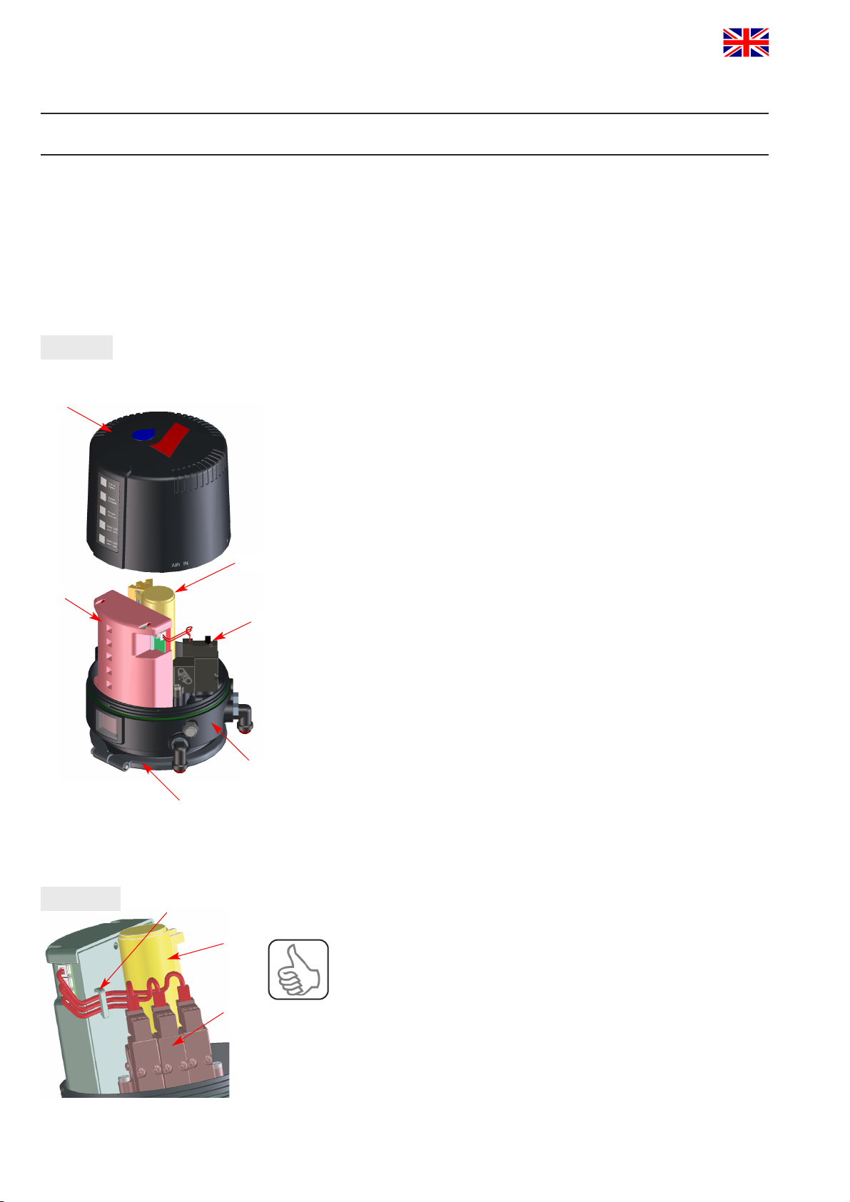
3.3. Function of the individual components
The installation of the control unit is undertaken by special
adapters which are available for the different valves types,
see chapter 5. Adapter. The snap connectors for supply air and
pneumatic air to the individual cylinders at the valves are located
at the outside of the control unit. At the control units for valves
with turning actuator, the pneumatic air is transferred internally to
the actuator. The air supply of the control unit is equipped with an
exchangeable air filter. Observance of the required compressed air
quality is imperative. Please also see chapter 4.5.
The number of the solenoid valves installed in the CU4 depends
on the valve actuators to be controlled. Single seat and butterfly
valves and double seat valves without seat lift function require 1
solenoid valve. Control units for double seat valves equipped
with 3 solenoid valves. For the manual actuation, the solenoid
valves are provided with a safe handle which is easy to operate.
The electronic module installed in the control unit fulfils the task
to process the electric signals from the control, to control the
solenoid valves and to evaluate the feedback signals from the
feedback unit. Moreover, the signalling and indication of the valve
positions as well as additional diagnostic functions are undertaken
via the electronic module.
The electronic module is the interface between control actuators or
sensors. Depending on the control type, different modules are
available, e.g. Direct Connect, AS-Interface, Profibus and
DeviceNet. The CU4 Direct Connect module described
here provides for the direct parallel wiring of the control.
A feedback unit is required to detect the valve position.
The CU4 Direct Connect is equipped with 2 adjustable Hall
effect sensors.
These are activated by a valve control rod installed on the
operating cam. In this way, the open and closed valve position
can be detected.
The 2 Hall effect sensors are continuously adjustable over an
additional range. Thus, feedback messages for different valves
with different stroke lengths can be adjusted properly. As an
alternative, external proximity switches can be connected instead
of the integrated Hall effect sensors when the valve position
indication is undertaken direct at the process valve.