Landmark L3015UI1 Series User manual

Landmark Service Manual
Landmark L3015UI1XXX Series
Landmark L3024UI1XXX Series
Landmark L3024UI2XXX Series
Wine Cooler
CAUTION: READ ALL SAFETY PRECAUTIONS IN
THIS MANUAL BEFORE SERVICING THE UNIT
*Warranty service should be performed by an authorized service representative only

2
SAFETY PRECAUTIONS
WARNING: This manual and the information contained herein is intended for use by certified technicians. The manu-
facturer or seller is not responsible for the interpretation or misuse of the information provided, nor does it assume
any liability in connection with its use.
The safeguards and warnings indicated in this manual do not cover all possible conditions which may occur. Common
sense, caution, and care must be exercised.
The design, color, and parts of this product are subject to change without prior notice.
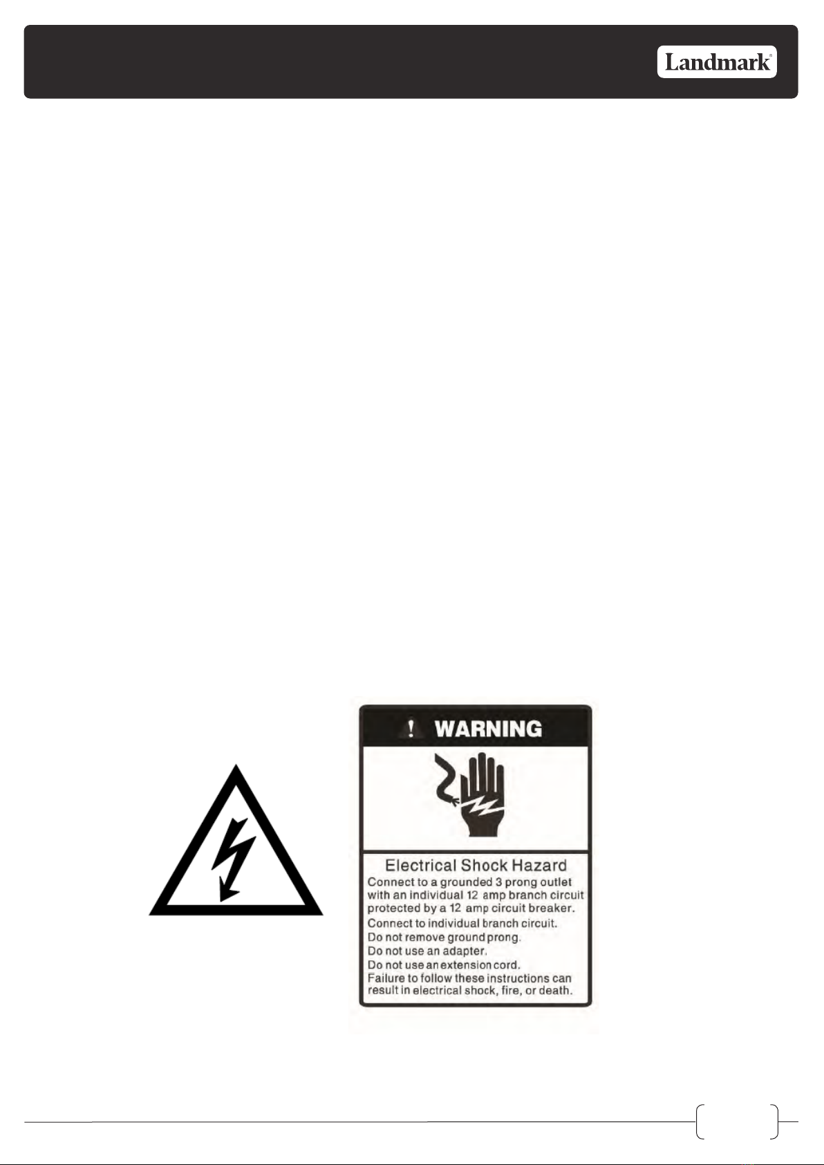
• To prevent electric shock, always unplug an appliance from the power supply before attempting any service.
• Disconnect the power cord by grasping the plug, not the cord.
• Do not bypass, cut, or remove the grounding plug.
• Prevent water from spilling onto electric elements or the machine parts.
• Always refer to the rating label on the appliance for rated current and voltage.
• Always check line voltage and amperage.
• Always use exact replacement parts.
• Any attempt to repair a major appliance may result in personal injury and property damage.
General Safety
• Always unplug an appliance from the power supply before attempting any service. Disconnect the power cord
by grasping the plug, not the cord.
• Do not allow children or pets to play on or in the appliance.
• This machine is not intended for use by persons (including children) with reduced physical, sensory or mental
capabilities, or lack of experience and knowledge, unless they have been given supervision or instruction
concerning use of the machine by a person responsible for their safety.
• Do not install or store this appliance where it will be exposed to the weather.
• Disconnect from the power socket before cleaning or maintenance.
• If the plug (power cord) is damaged, it must be replaced by the manufacturer or an authorized
service representative.
• This machine shall be repaired only by an authorized service representative. Only genuine replacement parts
should be used.
• If connected to a circuit protected by fuses, use time-delay fuses with this appliance.
• Do not lean items against the glass door.
• Please do not close the door with excessive force. If it is found dicult to close the door, please check
for obstruction.
• When you plan to dispose of this unit in the future, please comply with the local waste disposal regulations.
Remove any doors so that children and pets will not be trapped in the unit.

3
Electrical Safety
• Do not exceed the power outlet ratings.
• It is recommended that the unit be connected to its own circuit.
• A standard electrical supply that is properly grounded in accordance with the National Electrical Codeand all
state and local codes and ordinances is required.
• Do not use outlets that can be turned o by a switch or pull chain.
• Always turn the unit o and unplug it from the outlet when cleaning.
• Unplug the unit if it is not going to be used for an extended period of time.
• Do not operate the unit with a power plug missing the ground plug, a damaged cord, or a loose socket.
• Be sure the appliance is properly grounded.
• Do not bypass, cut, or remove the grounding plug.
• If the power cord is damaged, it must be replaced by the manufacturer or a qualified technician.
• Do not use extension cords or power strips with this unit. You may need to contact an electrician if it is
necessary to use a longer cord or if you do not have a properly grounded outlet. Do not modify the power
cord’s length or share the outlet with other appliances.
• Do not start or stop the unit by switching the electrical circuit’s power on and o.
• Immediately unplug the unit if it makes strange sounds, emits an odor or smoke and contact customer service.
• Do not remove any part of the casing unless instructed by an authorized technician.
• Before the appliance is removed from service or discarded, remove any doors and cut o the power cord.

4
Contents
Safety Precautions . . . . . . . . . . . . . . . . . . . . . . . . . . . . . . . . . . . . . . . . . . . . . . .2
Parts Identification . . . . . . . . . . . . . . . . . . . . . . . . . . . . . . . . . . . . . . . . . . . . . . .5
Disassembly . . . . . . . . . . . . . . . . . . . . . . . . . . . . . . . . . . . . . . . . . . . . . . . . . .8
Shelves . . . . . . . . . . . . . . . . . . . . . . . . . . . . . . . . . . . . . . . . . . . . . . . . . . . .8
Light . . . . . . . . . . . . . . . . . . . . . . . . . . . . . . . . . . . . . . . . . . . . . . . . . . . . .9
Display Board . . . . . . . . . . . . . . . . . . . . . . . . . . . . . . . . . . . . . . . . . . . . . . . 10
Control Board . . . . . . . . . . . . . . . . . . . . . . . . . . . . . . . . . . . . . . . . . . . . . . . 12
Sensor(S) And Fan. . . . . . . . . . . . . . . . . . . . . . . . . . . . . . . . . . . . . . . . . . . . . 16
Door Switch . . . . . . . . . . . . . . . . . . . . . . . . . . . . . . . . . . . . . . . . . . . . . . . . 23
Compressor/Ptc Starter/Overload Protector . . . . . . . . . . . . . . . . . . . . . . . . . . . . . . 25
Troubleshooting . . . . . . . . . . . . . . . . . . . . . . . . . . . . . . . . . . . . . . . . . . . . . . . 26
Compressor Components . . . . . . . . . . . . . . . . . . . . . . . . . . . . . . . . . . . . . . . . 26
Electrical Components . . . . . . . . . . . . . . . . . . . . . . . . . . . . . . . . . . . . . . . . . . 27
Service Diagnostic Chart . . . . . . . . . . . . . . . . . . . . . . . . . . . . . . . . . . . . . . . . . 28
Refrigerating Cycle . . . . . . . . . . . . . . . . . . . . . . . . . . . . . . . . . . . . . . . . . . . . 30
PCB Board . . . . . . . . . . . . . . . . . . . . . . . . . . . . . . . . . . . . . . . . . . . . . . . . . . 31
PCB Description . . . . . . . . . . . . . . . . . . . . . . . . . . . . . . . . . . . . . . . . . . . . . . 31
ADDITIONAL SAFETY PRECAUTIONS
Please read the followings before servicing your appliance.
1. Check if electric leakage occurs in the set.
2. To prevent electric shock, unplug prior to servicing.
3. In case of testing with power on, wear rubber gloves to prevent electric shock.
4. If you use any appliances, check regular current, voltage and capacity.
5. Don't touch metal products in cold freezer with wet hand. It may cause frostbite.
6. Prevent water flowing to electric elements in mechanical parts.
7. When sloping the set, remove any materials on the set, especially thin plate type. (ex.: glass shelf or books.)
8. When servicing evaporator part, wear cotton gloves without fail. It is to prevent wound by sharp fin of evaporator.
9. Leave a breakage of refrigerating cycle to a heavy service center. The gas in cycle inside may soil ambient air.

5
Carbon Filter
Door Handle
Door Lock
Leveling Legs
SS Door
Frame
Shelf
Lower Right Hinge
Control Panel
Door Switch
Top Right Hinge
Models: L3015UI1WSG-LH / L3015UI1WSG-RH
Carbon Filter
Door Handle
Door Lock
Leveling Legs
SS Door
Frame
Shelf
Lower Right Hinge
Control Panel
Door Switch
Top Right Hinge
PARTS IDENTIFICATION

6
PARTS IDENTIFICATION
Carbon Filter
Door Handle
Door Lock
Leveling Legs Door Switch
Lower Right Hinge
Control Panel
SS Door
Frame
Shelf
Top Right Hinge
Models: L3024UI1MSG-LH / L3024UI1MSG-RH
Models: L3024UI1BSG-LH / L3024UI1BSG-RH
Carbon Filter
Door Handle
Door Lock
Leveling Legs Door Switch
Lower Right Hinge
Control Panel
SS Door
Frame
Shelf
Top Right Hinge

7
PARTS IDENTIFICATION
Carbon Filter
Door Handle
Door Lock
Leveling Legs
Lower Right Hinge
Control Panel
SS Door
Frame
Shelf
Top Right Hinge
Door Switch
Models: L3024UI1WSG-LH / L3024UI1WSG-RH
Models: L3024UI2WSG-LH / L3024UI2WSG-RH
Carbon Filter
Door Handle
Door Lock
Leveling Legs Door Switch
Lower Right Hinge
Control Panel
SS Door
Frame
Shelf
Top Right Hinge
Carbon Filter

8
Shelves
DISASSEMBLY
L3015UI1WSG-LH / L3015UI1WSG-RH
L3015UI1BSG-LH / L3015UI1BSG-RH
L3024UI1MSG-LH / L3024UI1MSG-RH
L3024UI1BSG-LH / L3024UI1BSG-RH
L3024UI1WSG-LH / L3024UI1WSG-RH
L3024UI2WSG-LH / L3024UI2WSG-RH
Installing the shelves
1. Open the door completely. The door must be able to
open at least 90 degrees for the shelves to properly
clear the door gasket.
2. Identify the slots corresponding to your desired
shelf height. Ensure that all four (4) track slots -left
and right, front and back - are the same height so
that your installed shelf will be level.
3. Lift the front of the shelf [closest to you] at a 20
degree angle above the back of the shelf. Insert the
rear pegs on both sides of the shelf into the rear
vertical track mounting slots as shown in step "A"
below.
4. Push the rear pegs in. Then, set the front shelf pegs
into the front vertical track mounting slots as shown
in step "B" below.
MODELS:
Removing the shelves
1. Open the door completely. The door must be able to
open at least 90 degrees for the shelves to properly
clear the door gasket.
2. Holding both the left and right sides of the shelf you
intend to remove, lift the front up out of the key slot on
the front vertical tracks. Then pull the shelf out of the
cabinet and towards you. See step "A" below.
3. Pull the shelf approximately 1/3 out of the refrigerator
cabinet. The rear shelf pegs will disengage from the rear
vertical tracks as shown in step "B" below. With the front
of the shelf angled 20 degrees above the back of the
shelf, pull the shelf forward until it is completely removed
from the cabinet.

9
DISASSEMBLY
Light
L3015UI1WSG-LH / L3015UI1WSG-RH
L3015UI1BSG-LH / L3015UI1BSG-RH
L3024UI1MSG-LH / L3024UI1MSG-RH
L3024UI1BSG-LH / L3024UI1BSG-RH
L3024UI1WSG-LH / L3024UI1WSG-RH
L3024UI2WSG-LH / L3024UI2WSG-RH
MODELS:
Checking and changing the light
1. Use a flathead screwdriver or other tool to pry the
bottom light cover o of the unit.
2. Remove the bottom cover.
3. Check the wired connection for a loose connection.
4. If the wiring connection is not loose, change the light.
5. To change the light, unplug the light connector from
the wired connector and rempve the faulty light from
the groove.
6. Install the new light.
7. Reinstall the bottom light cover.
NOTE: The light connector and the wired
connector must be aligned, in the same
position.

10
Display Board
MODELS:
Checking and changing the display board
1. Remove the two screws from the display board
support panel.
2. Check the wired connector for a loose connection.
3. If the wired connection is not loose, change the
display board.
4. To change the display board, unplug the board from
the wired connector.
5. Remove the two screws from the board.
6. Remove the faulty display board.
7. Install a new supply board.
8. Reinstall the two display board screws.
9. Connect the new display board to the wired connector.
10. Replace the two screws in the display board
support panel.
L3015UI1WSG-LH / L3015UI1WSG-RH
L3015UI1BSG-LH / L3015UI1BSG-RH
L3024UI1MSG-LH / L3024UI1MSG-RH
L3024UI1BSG-LH / L3024UI1BSG-RH
L3024UI1WSG-LH / L3024UI1WSG-RH
DISASSEMBLY

11
2. Lift the display board support bracket.
Display Board
L3024UI2WSG-LH / L3024UI2WSG-RH
MODELS:
Checking and changing the display board
1. Remove the two screws from the middle display board
support bracket.
3. Check the wired connector for a loose connection.
4. If the wired connection is not loose, change the
display board.
5. Unplug the faulty board from the wired connector.
6. Remove the board from the bracket.
7. Install a new display board.
8. Place the new control board in
the bracket.
9. Connect the new display board to the wired connector.
10. Replace the display board support bracket in the unit
11. Replace the two screws in the support bracket.
DISASSEMBLY

12
Control Board
MODELS:
L3015UI1WSG-LH / L3015UI1WSG-RH
L3015UI1BSG-LH / L3015UI1BSG-RH
Checking and changing the control board
1. Remove the four screws from the back cover.
WARNING: Do not get water on the control board brack-
et or the compressor connector.
2. Remove the two screws from the water tank.
3. Remove the water tank and empty it.
4. Unscrew the three (3) screws from the control
board bracket.
5. Check the wired connectors for a loose connection.
6. If the wired connectors are not loose, change the
control board.
7. To change the control board, first disconnect all
wired connections.
NOTE: For the power cord connector, use a
needle inserted in the round hole to remove.
DISASSEMBLY

13
8. Remove the screws from the faulty control board.
DISASSEMBLY
9. Depress the standos by squeezing them with a
needle nose pliers.
10. Remove the old control board.
11. Install a new control board.
12. Reinstall the screws in the new control board.
13. Reconnect the wired connections to the control board.
14. Reinstall the board in the control board bracket with
the three screws.
15. Replace the water tank and its two screws.
16. Replace the back cover and its four screws.

14
DISASSEMBLY
Control Board
MODELS:
L3024UI1MSG-LH / L3024UI1MSG-RH
L3024UI1BSG-LH / L3024UI1BSG-RH
L3024UI1WSG-LH / L3024UI1WSG-RH
Checking and changing the control board
NOTE: For the power cord connector, use a needle
inserted in the round hole to remove.
1. Remove the four screws from the back cover.
2. Unscrew the four screws from the plastic box.
3. Check the wired connectors for a loose connection.
4. If the wired connectors are not loose, change the
control board.
5. To change the control board, first
disconnect all wired connections.
6. Remove the screws from the faulty controlboard.
7. Depress the standos by squeezing them with a needle
nose pliers.
8. Remove the old control board.
9. Install a new control board.
10. Reinstall the screws in the new control board.
11. Reconnect the wired connections to the control board.
12. Replace the plastic box and its four screws.
13. Replace the back cover and its four screws.

15
DISASSEMBLY
Control Board
MODELS:
Checking and changing the control board
L3024UI2WSG-LH / L3024UI2WSG-RH
1. Remove the four screws from the back cover.
2. Unscrew the four screws from the plastic box.
3. Check the wired connectors for a loose connection.
4. If the wired connectors are not loose, change the
control board.
5. To change the control board, first disconnect all
wired connections.
NOTE: For the power cord connector, use a needle inserted
in the round hole to remove.
6. Remove the screws from the faulty controlboard.
7. Remove the old control board.
8. Install a new control board.
9. Reinstall the screws in the new control board.
10. Reconnect the wired connections to the control board.
11. Replace the plastic box and its four screws.
12. Replace the back cover and its four screws.

16
DISASSEMBLY
Sensor(s) and Fan
MODELS:
L3015UI1WSG-LH / L3015UI1WSG-RH
L3015UI1BSG-LH / L3015UI1BSG-RH
Checking and changing the sensor(s)
and/or fan
1. Take out all the shelves.
2. Unscrew the three screws from the air duct board.
3. Use a hook or other tool inserted into one of the
holes to remove the air duct board.
4. Unscrew the six screws from the air duct boar
5. Pull open the air duct board and check the wired
connections to see if any are loose.
Wire Housing
Fan
Evaporator
Sensor

17
DISASSEMBLY
7. To replace the fan, unscrew the four screws.
8. Remove the faulty fan.
9. Install a new fan.
10. Replace the four screws.
6. If no connections are lose, replace the fan or the
sensor(s).
Fan
Defrost
Sensor
Sensor
11. To replace a sensor, remove the EVA and tinfoil.
12. Remove the sensor bracket.
13. Reverse the air duct board and remove the bracket.
14. Remove the sensor.
15. Replace the sensor with a new sensor.
16. Replace the bracket.
17. Replace the EVA and tinfoil.

18
DISASSEMBLY
Sensor(s) and Fan
MODELS:
L3024UI1BSG-LH / L3024UI1BSG-RH
L3024UI1WSG-LH / L3024UI1WSG-RH
L3024UI1MSG-LH / L3024UI1MSG-RH
Checking and changing the sensor(s)
and/or fan
1. Take out all the shelves.
2. Unscrew the three screws from the air duct board.
3. Use a hook or other tool inserted into one of the holes
to remove the air duct board.
4. Unscrew six screws from the air duct board.
5. Pull open the air duct board and check the wired
connections to see if any are loose.
Wire Housing
Fan
Evaporator
Sensor

19
DISASSEMBLY
6. If no connections are lose, replace the fan or the
sensor(s).
7. To replace the fan, unscrew the four screws.
8. Remove the faulty fan.
9. Install a new fan.
10. Replace the four screws.
11. To replace a sensor, remove the EVA and tinfoil.
12. Remove the sensor bracket.
Fan
Defrost
Sensor
Sensor
13. Reverse the air duct board and remove the bracket.
14. Remove the sensor.
15. Replace the sensor with a new sensor.
16. Replace the bracket.
17. Replace the EVA and tinfoil.

20
Sensor(s) and Fan
MODELS:
L3024UI2WSG-LH / L3024UI2WSG-RH
Checking and changing the sensor(s)
and/or fan
1. Remove the two screws from the middle display board.
2. Take out the display board support box.
3. Unplug the display board connector.
4. Take out thedisplay board box.
5. Unscrew the seven screws from the upper air duct
board cover.
6. Take out the upper air duct cover.
7. Unplug the LED light connector.
8. Unscrew five screws from the lower air duct board cover.
9. Take out the lower air duct board cover.
DISASSEMBLY
Other manuals for L3015UI1 Series
1
This manual suits for next models
14
Table of contents
Other Landmark Kitchen Appliance manuals

Landmark
Landmark L3024UI2WPR-LH User manual

Landmark
Landmark L3024UI2 Series User manual

Landmark
Landmark L3015UI1 Series User manual

Landmark
Landmark L3024UI1BSG-LH User manual

Landmark
Landmark L3015UI1WSG-RH User manual

Landmark
Landmark L3024UI2WPR-RH User manual

Landmark
Landmark 3024UI1MPR-RH User manual

Landmark
Landmark L3024UI1WPR-LH User manual