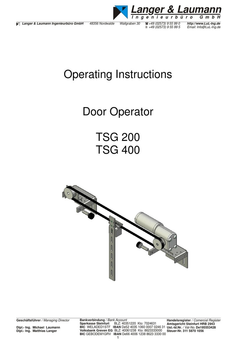
Langer & Laumann TSG V4 User manual

1
Installation and Operating Instructions
for the device series
Door Operator
TSG V4

2
Documentation history
No
Ver.
Status
Processed by
1
4.10
14.05.14
CSA
2
4.11
07.08.14
CSA
3
4.12
29.04.15
CSA
4
4.13
03.08.15
CSA
5
4.14
12.09.16
CSA
6
4.15
24.11.16
CSA
7
4.16
24.01.17
CSA
8
4.17
09.07.18
AL
9
4.18
25.11.19
CSA
Bedienungsanleitung in deutsch
durch Scannen des QR-Codes anfordern.
Demandez les instructions d´instruction de
montage en français, en scannant le code QR.
© 2020 Langer & Laumann Ingenieurbüro GmbH All rights reserved
All rights for these operating instructions and the product described therein are reserved for Langer & Lau-
mann Ingenieurbüro GmbH or their suppliers. In accordance with the laws of copyright protection, these
operating instructions may not be copied in whole or in part without written approval of Langer & Laumann
Ingenieurbüro GmbH, except as part of normal use of the product or to create a back-up copy. However, this
exceptional provision does not extend to copies created for third parties or that are sold or transferred to third
parties in any other manner. The whole of the material acquired (including all back-up copies) may, however,
be transferred to third parties or made available on loan. According to the provisions of the law, preparing a
translation also falls under the definition of copying.
Langer & Laumann Ingenieurbüro GmbH assumes no warranty or guaranty for the content of these
operating instructions. It declines any legal guaranty regarding the marketability or suitability for a
specific purpose. Langer & Laumann Ingenieurbüro GmbH is not responsible for errors in these operating
instructions or for direct or indirect damages associated with delivering, performing or using these operating
instructions. Langer & Laumann Ingenieurbüro GmbH reserves the right to revise these operating instruc-
tions from time to time without advance notification and to make changes to the content.
File: 1.20.91000_TSG_Betriebsanleitung_V4.18_en.docx
Printing date: 11/26/2019 9:49:00 AM

3
Table of contents
1Original EC declaration of incorporation__________________________________________________ 5
2About these instructions______________________________________________________________ 6
2.1 General information______________________________________________________________ 6
2.2 Explanation of symbols ___________________________________________________________ 6
3General safety requirements __________________________________________________________ 7
3.1 Delivery _______________________________________________________________________ 8
3.2 Safety and accident prevention requirements__________________________________________ 8
3.3 Qualified personnel as defined by VDE 0105 __________________________________________ 8
3.4 Exclusion of any guarantee when changes or conversions are made or installation of foreign
material_____________________________________________________________________________ 9
3.5 Safety contacts _________________________________________________________________ 9
3.6 Other important safety instructions _________________________________________________ 10
4Range of service applications for the TSG_______________________________________________ 11
5Illustrations _______________________________________________________________________ 12
5.1 Overview _____________________________________________________________________ 12
5.2 Assembly_____________________________________________________________________ 13
5.3 Mounting of the counter roller _____________________________________________________ 14
5.4 Dimensions ___________________________________________________________________ 15
5.5 TSG drive: position of motor ______________________________________________________ 16
5.6 TSG housing __________________________________________________________________ 17
6Mechanical installation ______________________________________________________________ 22
6.1 Requirements for installation______________________________________________________ 22
6.2 Installation process _____________________________________________________________ 22
6.3 TSG toothed belts ______________________________________________________________ 23
7Electrical settings and commissioning __________________________________________________ 24
7.1 Display_______________________________________________________________________ 24
7.2 Two-digit 7-segment display ______________________________________________________ 25
7.3Menu structure ________________________________________________________________ 26
7.4 Self-Learn Procedure ___________________________________________________________ 27
7.5 Enter the weight to be traversed ___________________________________________________ 28
7.6 Manual mode / manual travel _____________________________________________________ 30
8Default parameters_________________________________________________________________ 31
8.1 Drive curves with default parameters _______________________________________________ 31
8.2 Basis settings _________________________________________________________________ 32
8.3 User setting – P parameters ______________________________________________________ 32
9Advanced parameters ______________________________________________________________ 34
9.1 Drive curves with advanced parameters_____________________________________________ 34
9.2 Advanced menu _______________________________________________________________ 35
10 TSG signal connectors ____________________________________________________________ 48
10.1 Inputs X1 ___________________________________________________________________ 48
10.2 Outputs X2__________________________________________________________________ 50
11 Setting for force limiting ___________________________________________________________ 51
11.1 Maximum kinetic energy _______________________________________________________ 51
11.2 Maximum static force__________________________________________________________ 51
11.3 Obstruction detection in Closed direction __________________________________________ 52
11.4 Obstruction detection in Open direction ___________________________________________ 52
12 Special features _________________________________________________________________ 53
12.1 Holding torque in the end positions_______________________________________________ 53
12.2 Nudging ____________________________________________________________________ 54
12.3 Stop input___________________________________________________________________ 54
12.4 Leading limit switch ___________________________________________________________ 57
12.5 Mechanical transmission adjustment______________________________________________ 58

4
13 Troubleshooting _________________________________________________________________ 58
14 Service and maintenance __________________________________________________________ 64
15 Disposal _______________________________________________________________________ 65
16 Technical data for TSG electronic ___________________________________________________ 66
16.1 Overview of TSG electronic_____________________________________________________ 66
16.2 Technical data _______________________________________________________________ 67
16.3 Restart after power off and restoration of mains power _______________________________ 69
16.4 Internal fuse protection ________________________________________________________ 69
16.5 Plug / terminal assignment of TSG electronic _______________________________________ 70
16.6 Connection of external control voltage ____________________________________________ 76
16.7 Stop-function connection_______________________________________________________ 77
17 Connection circuit diagram for TSG inputs_____________________________________________ 78
18 TSG options ____________________________________________________________________ 79
18.1 TSG webinterface ____________________________________________________________ 79
18.2 Intermediate positions in the travel zone___________________________________________ 79
18.3 Emergency power supply ______________________________________________________ 80
18.4 Light Curtain Kit ______________________________________________________________ 81

5
1 Original EC declaration of incorporation
The manufacturer: Langer & Laumann Ing.-Büro GmbH
Wilmsberger Weg 8
48565 Steinfurt
Germany
Tel.: +49 (2552) 92791 0
declares herewith, the following product:
product: door operator
type / model: TSG V4
serial number: 040000000 – 040900000
year: as of 2013
the following complying with all essential requirements of the Machine Directive (2006/42/EG):
annex I, part 1.1.2, 1.1.3, 1.1.5, 1.2.1, 1.2.6, 1.3.2, 1.3.4, 1.3.7, 1.3.9, 1.5.1, 1.5.11, 1.7.1, 1.7.2, 1.7.3, 1.7.4.
The partly completed machinery is in conformity with the EC Directives (2014/30/EU).
The following harmonized standards were applied:
•EN ISO 13849-1: 2015
•EN 81-20: 2014
•EN 81-25: 2014
The partly completed machinery must not be put into service until the final machinery into which it is to be
incorporated has been declared in conformity with the provisions of Machine Directive (2006/42/EG).
The manufacturer undertakes to supply, in response to a reasoned by the market surveillance authorities,
relevant documents on the partly completed machinery by documentation department in electronically way.
The special technical documentation belonging the machine, referred to in annex VII part B, have been cre-
ated.
Name of authorized person for documentation: Langer & Laumann Ing. -Büro GmbH.
Address of authorized person for documentation: see address of manufacturer.
Steinfurt, 01.01.2020
________________________________________ _________________________________________________________________________
place, date Dipl.-Ing. Martin Platt
managing director

6
2 About these instructions
2.1 General information
Please read this operating instruction attentively before you install the TSG door operator and put into opera-
tion. Note the cap. 3 General safety requirements / page 7. For further using please keep the operating in-
structions on hand.
The operating instructions are to assist you to mount the TSG door operator and its components and to put
into operation. The operating instructions contain important information for safely and correctly to mount the
TSG door operator and put into operation.
The operating instructions are applicable for the TSG door operator from hardware version V4.05, line filter
4.04 and software version V4.60.12.
By following this operation instruction, you will avoid danger, costs of repair, downtime, increase reliability and
service life of the TSG door operator.
In addition to our recommendations, it is imperative to comply with any local safety regulations that may be in
force in the country where the operator is installed.
The manual only applies to components supplied by Langer & Laumann Ing. -Büro GmbH for any other com-
ponent used, please refer to the supplier’s instructions.
The manual describes the standard TSG door operator application only. Due to the wide range of its applica-
tion, these may not apply to all the application possible. Please consult Langer & Laumann Ing. -Büro GmbH
(+49 (2552) 92791 0) for any special application.
2.2 Explanation of symbols
WARNING:
This symbol directs your attention to a possible hazard that could lead to severe bodily injuries
or death.
CAUTION:
This symbol directs your attention to a possible hazard that could lead to minor bodily injuries.
The same symbol is also used to warn of potential damage to property.
NOTE:
Your attention is drawn to applications and other useful information.

7
3 General safety requirements
The TSG door operator is designed exclusively for operation of horizontal and vertical sliding doors or remov-
able protection device. The manufacturer assumes no liability for applications that fall outside the defined area
of usage. The TSG door operator carries electrical and mechanical hazards. Failure to observe the instructions
in these operating instructions may result in death, severe bodily injuries or significant property damage.
The TSG door operator is built according to the state of the art and recognized safety engineering rules and is
intended exclusively for normal industrial usage. If it is used for any other purpose, the manufacturer must in
every case be consulted. Otherwise no liability is assumed for personal injury or property damage. Any other
or more extensive use is considered contrary to designated use and may result in personal injury for the user
or third parties as well as damage to property.
WARNING:
When electrical devices are in operation, certain parts of the devices conduct dangerous volt-
age. Failure to observe the operating instructions may therefore result in serious bodily injuries
or property damage! Observance of the warning notices in these operating instructions is ab-
solutely mandatory. While the TSG is starting up, door movements cannot always be controlled
externally. During commissioning, an authorized person located at the door must ensure that
no other persons can reach the area close to the door. Permissible forces and energy levels must be checked
by a qualified person after the door has been commissioned.
WARNING:
The TSG door operator has to be installed so that hazards are excluded to moving points (e.g.
installation of protection devices to motor shaft, counter roller, tooth belt).
WARNING:
When operating on a vertically guided door care must be taken to ensure that it cannot lead to
uncontrolled movements in the failure of the TSG door operator. This can be prevented by, for
example, use of counterweights. It is necessary to provide a customer-supplied mounting pro-
tection against means breakage. The exporting specialist must check the structure correspond-
ing to the commissioning at the door.

8
3.1 Delivery
Using the delivery note and the operating instructions, check the delivered components to ensure complete-
ness. At the same time perform a visual inspection for damage of delivered materials. While unpacking, check:
- Whether there is any visible mechanical damage to components.
- Whether the lengths of the cables included with delivery are correct.
CAUTION:
Electrostatic discharge, mechanical load, moisture and dirt will damage or destroy electronic
components.
Leave electronic components in their original packages until they are installed.
If damage occurred during shipping, a claim must be filed immediately with the shipping company.
If components are missing, inform the supplier immediately.
3.2 Safety and accident prevention requirements
In addition to the instructions in these operating instructions, you must also observe safety and accident pre-
vention requirements as specified by law. Persons responsible for the safety of the system must ensure the
following:
- Only appropriately qualified personnel are permitted to work on and with the TSG door operator.
- All personnel who work with the TSG door operator must be familiar with all warning signs and
measures listed in the description here for installation, control and operation of the TSG door operator.
- Unqualified personnel are prohibited from working on the TSG door operator.
- Personnel must have knowledge of first aid measures and on-site rescue equipment.
3.3 Qualified personnel as defined by VDE 0105
Qualified personnel mean persons who has received by virtue of their training, experience, instructions and
knowledge of applicable standards, specifications, accident prevention requirements and operating conditions
have been authorized by the person responsible for the safety of the system to perform necessary activities.

9
3.4 Exclusion of any guarantee when changes or conversions are made
or installation of foreign material
Before any work is performed on the electrical or mechanical parts of the system, the TSG door operator must
be disconnected from the mains voltage. Unauthorized changes or conversions to or in the TSG door operator,
its components or accessories or installation of foreign material will automatically exclude all claims under the
warranty. These safety instructions do not claim to be complete. The manufacturer assumes no liability for
damages or operating malfunctions which may occur due to failure to observe these operating instructions.
WARNING:
Unauthorized changes to the drive or installation of non-original replacement parts shall exclude
any liability on the part of the manufacturer for resulting damages.
WARNING:
By using connecting cable between TSG electronic and TSG motor other than provided from
L&L forfeit the examination certificate 44780 130999930301 and the certificate of conformity for
equipment manufacturer.
3.5 Safety contacts
The relay outputs of the TSG door operator must not be used as safety contacts to the safety circuit of the
higher-level control unit.
WARNING:
If the higher-level control unit undergoes an Emergency Stop or Off, it must be ensured that the
TSG door operator will not cause any unintentional, dangerous or uncontrolled door move-
ments.

10
3.6 Other important safety instructions
The purchaser, designer and/or fitter of the TSG door control unit and its components is responsible for its
correct and safe use. He must ensure that all state and local laws and regulations regarding the safety of
power-operated doors as well as the relevant state health and safety regulations are observed.
Langer & Laumann Ing. -Büro GmbH is not responsible for accidents and/or consequential damage that
could result from the application or use of the door control unit TSG and its components. Our maximum obli-
gation and warranty is limited to the reimbursement of the costs of the sold product.
Langer & Laumann Ing. -Büro GmbH makes no specifications or recommendations for suitability for specific
safety gate concepts. The purchaser, designer and/or installer of the TSG door control unit must decide for
himself whether the drive is suitable for a given application. Langer & Laumann Ing. -Büro GmbH also de-
clines all responsibility for damage or injury resulting from changes to the drive, including changes to soft-
ware parameters. Employees of Langer & Laumann Ing. -Büro GmbH are not authorized to modify these
conditions without the written consent and legally valid signature of the responsible authorities.

11
4 Range of service applications for the TSG
The TSG door operator is a door drive for the automatic operation of moving horizontally or vertically sliding
doors or removable protection device. The manufacturer assumes no liability for applications that fall outside
the defined area of usage. The speed and acceleration settings can be adjusted. The door opening width is
determined by a measurement process.
When operating the TSG door operator as removable protection device it meets the requirements of the DIN
EN ISO 13849-1:2015 with category 2 / Performance Level d.
The TSG 4xx can be use up to 20.000[mm] travel distance, if the door panels weights 400[kg] not exceed.
CAUTION:
Gear reductions or increases on the TSG toothed belt change kinetic and static forces! When
it happens, the door width is no longer valid.

12
5 Illustrations
5.1 Overview
Fig. 1: TSG assembly example
Table 1: Designation of TSG universal kit
No.
Article number
Designation
1.
8.20.40000.X1
TSG drive (shown here: left version)
2.
1.20.60040
TSG standard combination bracket
3.
1.20.60030
TSG stop kit (incl. buffer stop)
4.
1.20.60003
TSG counter roller
5.
1.20.60110
TSG clamping latch
6.
1.20.60013
TSG counter roller support
7.
1.20.60005
TSG toothed belt lock
8.
1.20.60004
TSG door panel carrier
9.
1.20.60020
TSG stop on door panel carrier

13
5.2 Assembly
Fig
. 2: Assembly TSG counter roller unit
Fig.
3: Assembly TSG door panel carrier unit
Fig.
4: Assembly TSG motor unit

14
5.3 Mounting of the counter roller
When mounting the counter roller make sure, it is fastened to the side of the pressed-board disk in direction
of the holder.
Fig. 5: TSG counter roller - mounted

15
5.4 Dimensions
Fig. 6: TSG universal kit - front dimensions
Fig. 7: TSG universal kit - side dimensions

16
5.5 TSG drive: position of motor
There are two different motor positions available:
The motor position is independent of the direction of opening of the door or the protective device. For example,
the TSG drive can be installed on the left or on the right side.
Fig. 8: TSG drive - version left
TSG drive left version (in view of the gear head and
foot mounting below is the output of the gear on the
left side).
Fig. 9: TSG drive - version right
TSG drive right version (in view of the gear head
and foot mounting below is the output of the gear
on the right side).

17
5.6 TSG housing
The TSG electronic is available in two different housing types.
5.6.1 TSG electronic intern
The TSG electronic is available in a cabinet housing. The cabinet version can be directly screwed in the cabinet
onto the mounting plate and / or be mounted on a DIN rail (TS35, 35[mm] x 7,5[mm]).
Fig. 10: TSG electronic intern – front view
Fig. 11: TSG electronic intern – contact power
(see also cap. 16.5.5 Terminal assignment power / page 74)

18
The motor and encoder cable and single wire for the inputs and outputs are introduced from the bottom. The
power supply is above and pluggable.
Fig. 12: Guide of the TSG cable in TSG housing
Condition for the use of the cabinet housing is to use a plug-in TSG drive and TSG cable. TSG cables are
available in lengths of 2.5, 5.0, 10.0, 15.0 and 20.0[m].
WARNING:
We would like to point out that we do not accept any warranty for errors arising from material
supplied by Langer & Laumann Ing. Büro GmbH, in particular motor or encoder cables. The
use of non-released cables invalidates the type examination certificate 44780 1309930301 and
the certificate of conformity for the manufacturer's equipment.
CAUTION:
The TSG electronic can be placed internally in the cabinet in at least 5[cm] distances between
each other and at least 2[cm] next to each other.
Table 2: Dimensions
Outer dimensions TSG cabinet housing
Width
205[mm]
Height
140[mm]
Depth
160[mm]
Table 3: Weight
Weight of TSG cabinet housing incl. TSG electronic
Weight
ca. 4,1[kg]

19
5.6.1.1 Dimensional / mounting drawing
Fig. 13: TSG intern, front view
Fig. 14: TSG intern, rear view
Fig. 15: TSG intern, top view

20
5.6.2 TSG electronic extern
The TSG electronic is available in a splash-proof housing. The housing is mounted by four screws to an ap-
propriate position near the TSG drive fixed.
Fig. 16: TSG electronic in splash-proof housing
The cables can be optionally inserted through the left or right side with cable glands through pro-punched
holes in the housing. The motor and encoder cables use a common, split cable gland.
CAUTION:
When you open the pre-cut holes for the cable glands, ensure that the TSG electronics will not
be damaged and no metalic parts enter to it.
CAUTION:
All broken out openings must be closed with the enclosed screw connections in order to main-
tain the degree of protection.
Table 4: Dimensions
Outer dimensions TSG splash-proof housing
Width
450[mm]
Height
95[mm]
Depth
155[mm]
Table 5: Weight
Weight of TSG splash-proof housing incl. TSG electronic
Weight
ca. 4,1…5,8[kg] (weight will vary by equipment)
Table 6: cable diameter glands
Cable diameter for enclosed glands
Gland M16
5 – 10 [mm]
Gland M20
8 – 13 [mm]
Table of contents
Other Langer & Laumann Garage Door Opener manuals
Popular Garage Door Opener manuals by other brands

Craftsman
Craftsman 139.53225SRT1 owner's manual

Teckentrup
Teckentrup CarTeck Installation, operating and maintenance instructions

moore o matic
moore o matic Z150 series Installation and operation manual

Pujol
Pujol SENIOR 1 Digital Series Installation and adjustment instructions

Accessmatic
Accessmatic cyborg Panther 1200 user manual

RYTEC
RYTEC Spiral SST installation manual

B&B ARMR
B&B ARMR 4X0E Series installation manual

BFT
BFT ARES ULTRA BT A 1500 Installation and user manual

Chamberlain
Chamberlain K74-16420 installation instructions

RIB
RIB Idro Series Operating and installation instructions

idomus
idomus IDO-HOME user manual

Chamberlain
Chamberlain SECURITY+ Elite Series owner's manual