4. Technical data
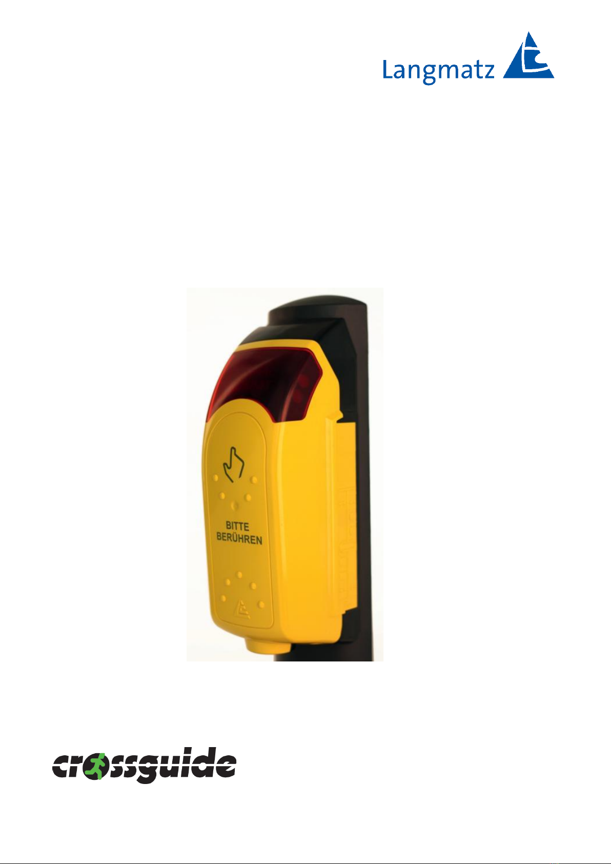
Designation EK 533 plus 2.0 pedestrian signal requesting
device for the visually impaired
Operating voltage 24 - 40 V AC/DC | 24 - 230 V AC
must be set in cgManager
(see Page 45, Fig. 66).
Housing colour Yellow, similar to RAL 1023, solid coloured
STANDARD, other colours available upon
request.
Housing material Polycarbonate, PC
Protection class II
Protection rating IP54
Safety SIL 2
Power consumption Typically 7 W | Maximum 13 W
Mounting 2 x A2/M6 x 25 hexagon socket screws
Lighting-pole adaptor Universal, stainless steel,
suitable for a diameter of 89 mm, 108 mm and 159
mm Optionally available: Lighting-pole adaptor >
diameter 159 mm and wall installation
Operating temperature -25 °C to +60 °C
H/W/D 256 mm/107 mm/68 mm (distance from pole)
Acoustic frequency range 180 - 17,000 Hz
Release signal (RS) clock
frequency as per DIN
32981:2015-10
Default settings: 1 Hz; 4 Hz and 6 Hz
(dependent on traffic noise);
Customised settings possible
Acoustic volume at a distance of
1 m as per DIN 32981:2015-10
Dependent on traffic noise, min. 35 dB(A) to max.
90 dB(A); in combination with a remote speaker
Customised settings possible
Acoustic sounds Freely selectable; new sounds can be uploaded to the
device, (wave) voice output possible
Parameter adjustment Via USB cable, via serial cable or via Bluetooth
Device satisfies the following standards DIN VDE 0832-100, 200 EN50293:2000
DIN 32981:2015-10
ÖNORM V2100, V2101
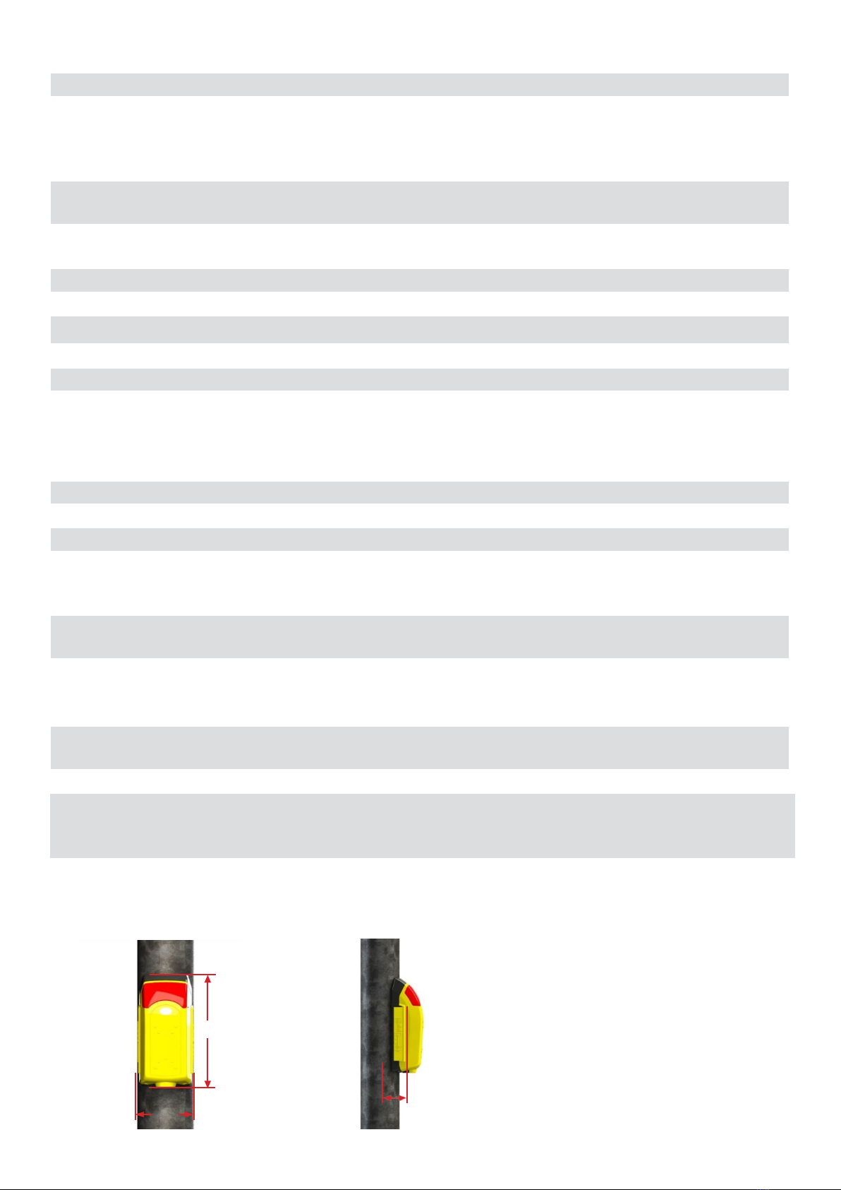
4.1 Dimensions
256
68
107
Fig. 1 Fig. 2