Lantronix PremierWave Enterprise Wi-Fi 2050 User manual
Other Lantronix Control Unit manuals
Lantronix
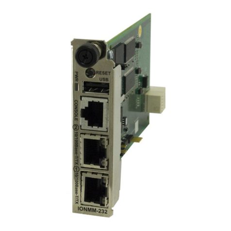
Lantronix IONMM-232 User manual
Lantronix
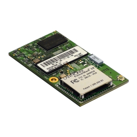
Lantronix PremierWave User manual
Lantronix
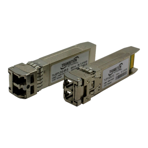
Lantronix TN-SFP 25G R-S Series User manual
Lantronix
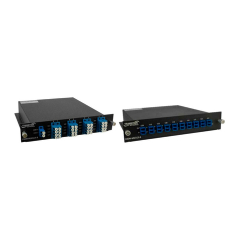
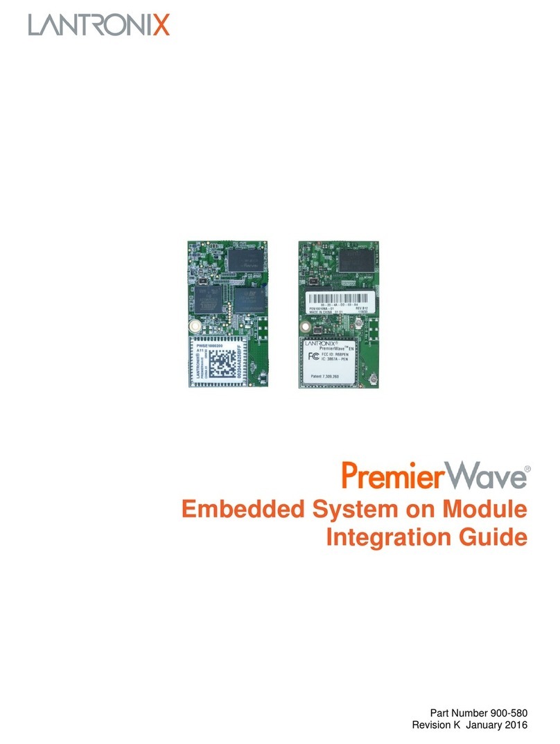
Lantronix CWDM-CR-B Series User manual
Lantronix
Lantronix PremierWave EN Quick setup guide

Lantronix
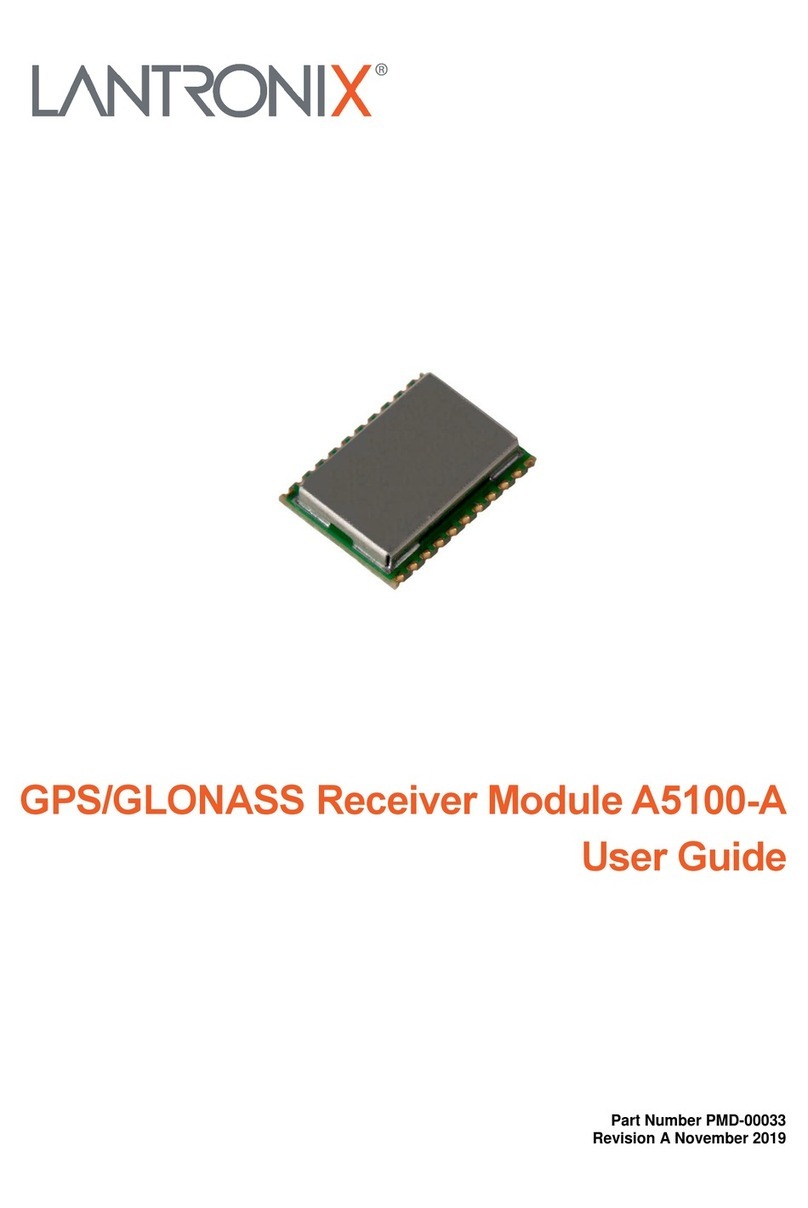
Lantronix PremierWave 2050 Quick setup guide
Lantronix
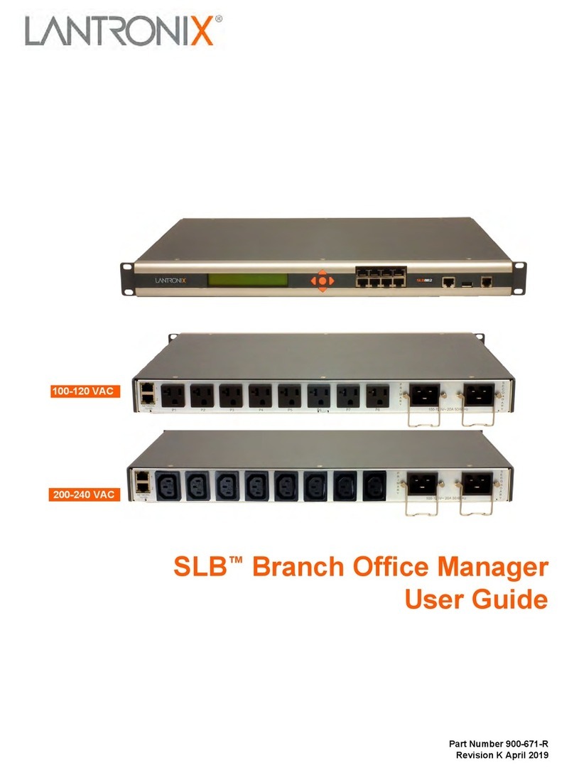
Lantronix A5100-A User manual
Lantronix
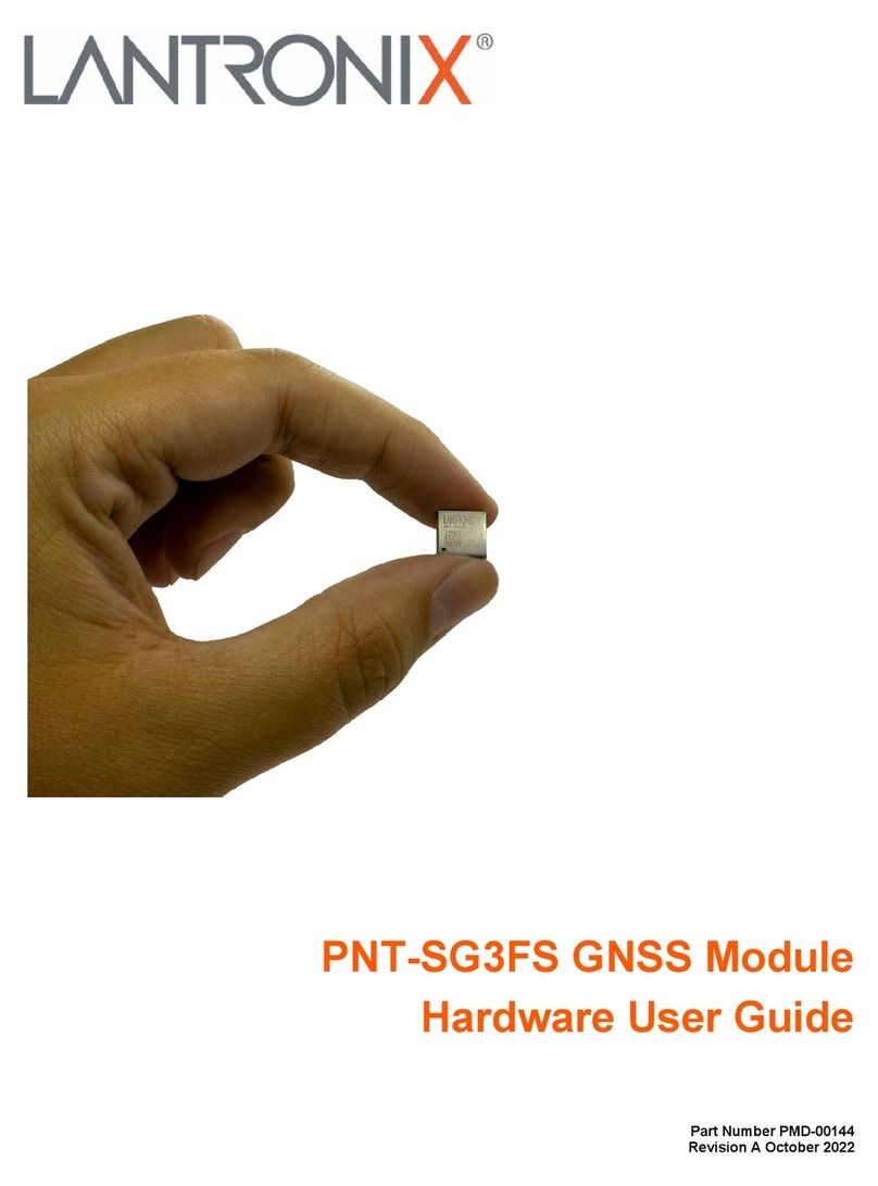
Lantronix 100-120 VAC SLB User manual
Lantronix
Lantronix PNT-SG3FS Installation manual

Lantronix
Lantronix PremierWave 2050 Installation manual
Popular Control Unit manuals by other brands

Festo
Festo Compact Performance CP-FB6-E Brief description

Elo TouchSystems
Elo TouchSystems DMS-SA19P-EXTME Quick installation guide

JS Automation
JS Automation MPC3034A user manual

JAUDT
JAUDT SW GII 6406 Series Translation of the original operating instructions

Spektrum
Spektrum Air Module System manual

BOC Edwards
BOC Edwards Q Series instruction manual

KHADAS
KHADAS BT Magic quick start

Etherma
Etherma eNEXHO-IL Assembly and operating instructions

PMFoundations
PMFoundations Attenuverter Assembly guide

GEA
GEA VARIVENT Operating instruction

Walther Systemtechnik
Walther Systemtechnik VMS-05 Assembly instructions

Altronix
Altronix LINQ8PD Installation and programming manual


