manuals.online logo
Brands
  1. Home
  2. •
  3. Brands
  4. •
  5. Lantronix
  6. •
  7. Switch
  8. •
  9. Lantronix Spider Duo SLSLP400USB-02 User manual

Lantronix Spider Duo SLSLP400USB-02 User manual

1
HARDWARE INSTALLATION AND NETWORK SETTINGS
Spider Duo Quick Start Guide Remote KVM-Over-IP
with Local Access
!Thank you for choosing Lantronix. Please register your product to receive nocaons for rmware and
documentaon updates at www.lantronix.com/product-registraon.
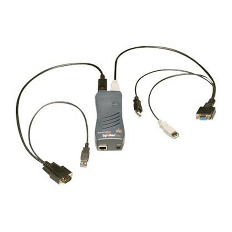
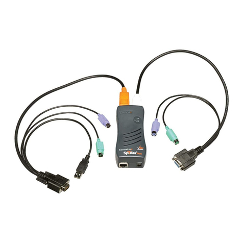
There are two Spider Duo models: one with both PS/2 and USB keyboard/mouse interfaces (soware selectable), and one for USB-only systems. The color-coded
plugs on the ends of the cable for the keyboard, mouse, USB port and video are designed to plug directly into the target system’s corresponding connector.
An oponal power control unit (PCU) is available (part number PCU100-01); see page 2 for details.
Quick Start Guide Accessories Part Number
Spider Duo
or
Local KVM cable N/A
Computer input cable N/A
Mounng kit N/A
Null modem DB9F to RJ95 serial cable
(30.48 mm; 120 in) N/A
External AC/DC Power Supply ACC-520-0184-00
WHAT’S IN THE BOX
Part # SLSLP400USB-02
START
1. Plug the RJ45 end of the included serial cable into the Spider Duo’s
serial port. Plug the DB9F end into the serial (COM) port of a
PC/laptop running a terminal emulaon (e.g. HyperTerminal). The
default serial port sengs are 9600 bits per second, 8 data bits, no
parity, 1 stop bit, no ow control.
Plug the power adaptor into the Spider Duo’s power connector.
Plug an Ethernet cable connected to your network into the Ethernet
port. The Link LED illuminates.
2. Insert color coded plugs into connectors with matching border on
the Spider Duo. Plug the video, USB, and PS/2 keyboard/mouse (if
applicable) cables into the target computer. For transparent local
access, connect cables to local keyboard, video, and mouse. The
blue Sys OK LED will illuminate and ashes to indicate that it is
boong up. Bootup is complete within approximately one minute.
The blue Sys OK LED stops ashing and remains illuminated.
3. Upon bootup, the terminal window displays the IP Conguraon
screen.
4. At the command prompt type cong and press Enter.
5. To change the default IP auto conguraon from DHCP to a stac IP
address, at the IP autoconguraon prompt type none and press
Enter.
6. Enter the unit’s IP address, subnet mask, default gateway, and LAN
interface informaon.
7. Type y and press Enter to accept the changes. The system takes
about 20 seconds to complete. Press Enter once again at the prompt
to display the updated IP address.
8. Plug an Ethernet cable connected to your network into the Ethernet
port. The Link LED illuminates.
Port Descripon
LED Color Descripon
ID Amber Oponally lit to assist in
nding unit.
Sys OK Blue Blinks upon bootup. Steady
when up and healthy.
PCU Green Steady on when power is
being supplied through
PCU.
Indicator LED Descripon
Welcome!
Choose a command for the following features:
-Initial IP configuration: “config”.
-Change default sysadmin password: “password”.
-Exit quick setup: “quit”.
[172.18.0.100 SL5a38bffdc]>
[172.18.0.100 SL5a38bffdc]> config
IP autoconfiguration (none/dhcp/bootp) [dhcp]: none
IP [172.18.0.100]:
NetMask [255.255.255.0]:
Gateway (0.0.0.0 for none) [172.18.0.100]:
LAN interface speed (auto/10/100/1000) [auto]:
LAN interface duplex mode (auto/half/full) [auto]:
Are the entered values correct? Enter y for Yes, n for No or c to Cancel y
Configuring device...
Done.
Part # SLSLP400PS2-02
Pinouts
Pin # RS-232 PCU
1RTS —
2—+5V
3TX —
4Ground Sense
5Ground Ground
6RX —
7—Relay driver
8CTS —
Serial/PCU Port Pinouts
HARDWARE OVERVIEW
Typical Spider Duo Conguraon
2
TARGET COMPUTER SETUP
© 2022 Lantronix, Inc. Lantronix is a registered trademark of Lantronix, Inc. All other trademarks are the property of their respecve
owners. Specicaons subject to change without noce. 895-0067-00 Rev. A
Contact Technical Support
For technical support queries, visit hps://www.lantronix.com/technical-support
For the latest rmware downloads, visit hps://www.lantronix.com/support/downloads
CONNECTION TO TARGET COMPUTER + BASIC OPERATIONS
POWER CONTROL UNIT (PCU)
SPIDER DUO WEB CONFIGURATION
The oponal PCU can be used to remotely manage power of the
target computer. In addion to the PCU module, the box contains
the following items:
• AC Power cord (input)
• AC Power cord IEC60320/C13 to IEC60320/C14 (output)
• Cable RJ45 to RJ45, CAT-5 (10 )
1. Click the KVM Console link from the Home page to begin remote
control of the aached target computer; the Remote Console
session will open in a new browser tab. (Note: Do not close the Spi-
der Duo home page web browser tab; closing the tab ends the Re-
mote Console session).
2. To operate within the remote target system, click your mouse
buon anywhere within the Remote Console desktop (Viewport).
The mouse will navigate along the remote target system’s screen.
3. To resize the Viewport, use the Screen Display Adjustment toolbar
buons in the top-right corner of the Viewport.
4. To restore local mouse control, press the Esc key.
5. To exit the Remote Console session, click the X buon in the Screen
Display Adjustment toolbar. To log out of the Spider Duo Home
page, click Logout.
PCU INSTALLATION
1. Connect power output plug to target PC.
2. Connect RJ45 cable from PCU to Spider Duo PCU
CTRL port.
3. Connect power input plug to AC power.
Spider Duo Quick Start Guide Remote KVM-Over-IP
with Local Access
1. Access the Spider Duo over the network using a web browser (such
as Chrome, Edge, or Firefox) by entering hps:// and its IP address in
the address bar.
2. Enter the user name (default is sysadmin) and password (default is
PASS) at the prompt. The Spider Duo home page displays.
3. The following are a few key conguraons:
Keyboard/Mouse (SLSLP400PS2-02 model only):
a.Select Interfaces › Keyboard/Mouse from the web page.
b.To change the target interface keyboard/mouse sengs from the
default (Auto) to force PS/2 or USB target interface, select the
appropriate opon from the Host Interface drop-down menu.
c.Click Save to store your sengs in nonvolale memory.
Network TCP Ports and Services:
a.Select Interfaces > Network from the web page.
b.Under Network Miscellaneous Sengs, modify the ports as
necessary. The client system requires the ability to access the
Spider Duo’s IP address as well as have port 443 (HTTPS) open.
Consult your system administrator if your system’s rewalls and
NAT device requires reconguraon or changes to these values.
c.Click Save.
Performance:
a.Select Interfaces › KVM Console Sengs from the web page.
b.If necessary, under Transmission Encoding, modify the video
encoding and compression sengs for slower connecons.
c.Click Save.
The Spider Duo recognizes several variees of video display formats
with resoluons up to 1600 x 1200 @ 60 Hz. (Refer to the User Guide
for a list of supported video formats).
1. On the Windows target system, select Control Panel › Display ›
Sengs. Modify the screen resoluon value as necessary.
2. Select Control Panel › Display › Sengs › Advanced › Monitor.
Modify the screen refresh rate (consult the appropriate
documentaon when using a typical video card or another operang
system on the target computer).
3. On the Windows target system, select Control Panel › Mouse ›
Pointer Opons, set the pointer speed to medium and disable
Enhanced pointer precision. For Linux GUIs, set the mouse
acceleraon to exactly 1 and the threshold to exactly 1.
Lantronix ConsoleFlow™
hps://consoleow.com
Client System Requirements: The client system must have a web browser (such as Chrome, Edge, Firefox, or Safari).
This manual suits for next models

1

Other Lantronix Switch manuals

Lantronix SM TAT4X Series User manual

Lantronix

Lantronix SM TAT4X Series User manual

Lantronix SISPM1040-582-LRT User manual

Lantronix

Lantronix SISPM1040-582-LRT User manual

Lantronix SM12XPA User manual

Lantronix

Lantronix SM12XPA User manual

Lantronix LSS2200-8P User manual

Lantronix

Lantronix LSS2200-8P User manual

Lantronix LSS2200-8P User manual

Lantronix

Lantronix LSS2200-8P User manual

Lantronix SISPM1040 L3 Series User manual

Lantronix

Lantronix SISPM1040 L3 Series User manual

Lantronix SM8TAT2SA User manual

Lantronix

Lantronix SM8TAT2SA User manual

Lantronix Xpress-Pro SW 52000 User manual

Lantronix

Lantronix Xpress-Pro SW 52000 User manual

Lantronix SecureLinx Spider User manual

Lantronix

Lantronix SecureLinx Spider User manual

Lantronix Series 1000 User manual

Lantronix

Lantronix Series 1000 User manual

Lantronix EDS4100 User manual

Lantronix

Lantronix EDS4100 User manual

Lantronix 300.000.4000 User manual

Lantronix

Lantronix 300.000.4000 User manual

Lantronix SISPM1040-582-LRT User manual

Lantronix

Lantronix SISPM1040-582-LRT User manual

Lantronix Xpress-Pro SW 92000 User manual

Lantronix

Lantronix Xpress-Pro SW 92000 User manual

Lantronix SM24TBT2DPB User manual

Lantronix

Lantronix SM24TBT2DPB User manual

Lantronix SUN-PC User manual

Lantronix

Lantronix SUN-PC User manual

Lantronix SESPM1040-541-LT Series User manual

Lantronix

Lantronix SESPM1040-541-LT Series User manual

Lantronix LSS2200-8P User manual

Lantronix

Lantronix LSS2200-8P User manual

Lantronix Xpress-Pro SW 52000 Manual

Lantronix

Lantronix Xpress-Pro SW 52000 Manual

Lantronix SM24TBT2DPA User manual

Lantronix

Lantronix SM24TBT2DPA User manual

Lantronix LSB4 User manual

Lantronix

Lantronix LSB4 User manual

Lantronix SM TAT2SA Series User manual

Lantronix

Lantronix SM TAT2SA Series User manual

Lantronix SLC 8000 Series User manual

Lantronix

Lantronix SLC 8000 Series User manual

Lantronix LFH8-S User manual

Lantronix

Lantronix LFH8-S User manual

Popular Switch manuals by other brands

Intellinet 561808 instructions

Intellinet

Intellinet 561808 instructions

Broadcast Tools SS 8.1 II Installation and operation manual

Broadcast Tools

Broadcast Tools SS 8.1 II Installation and operation manual

Zamel RWS-311D/Z manual

Zamel

Zamel RWS-311D/Z manual

Intellinet 520409 user manual

Intellinet

Intellinet 520409 user manual

Brocade Communications Systems SILKWORM 4016 quick start guide

Brocade Communications Systems

Brocade Communications Systems SILKWORM 4016 quick start guide

Elko iNels RFSA-61M manual

Elko

Elko iNels RFSA-61M manual

NETGEAR GSM7352SNA - Prosafe 48 Port Gigabit L3 Managed Stackable... installation guide

NETGEAR

NETGEAR GSM7352SNA - Prosafe 48 Port Gigabit L3 Managed Stackable... installation guide

D-Link xStack DGS-3612G series Specifications

D-Link

D-Link xStack DGS-3612G series Specifications

Ecus POWER 2S manual

Ecus

Ecus POWER 2S manual

SMC Networks PF3AmH Series manual

SMC Networks

SMC Networks PF3AmH Series manual

FS S3900 Series quick start guide

FS

FS S3900 Series quick start guide

Intellinet 560993 instructions

Intellinet

Intellinet 560993 instructions

Raritan DOMINION DKX116 user guide

Raritan

Raritan DOMINION DKX116 user guide

Ubiquiti EdgeRouter ER-10X quick start guide

Ubiquiti

Ubiquiti EdgeRouter ER-10X quick start guide

Accton Technology Edge-Core ES4528V installation guide

Accton Technology

Accton Technology Edge-Core ES4528V installation guide

schmersal AZM300Z-ST-1P2P-DU Instructions for operation

schmersal

schmersal AZM300Z-ST-1P2P-DU Instructions for operation

AMX VPX-1401 user manual

AMX

AMX VPX-1401 user manual

Microsens MS453526M Hardware manual

Microsens

Microsens MS453526M Hardware manual

manuals.online logo
manuals.online logoBrands
  • About & Mission
  • Contact us
  • Privacy Policy
  • Terms and Conditions

Copyright 2025 Manuals.Online. All Rights Reserved.