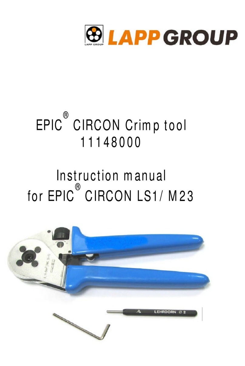
Lapp Group PEW 12 User manual

Rev.: 2022-02-01 (Bilder können abweichen)
Crimp-Systemzange
PEW 12
Bedienungsanleitung DE
Die Crimp-Systemzange ist nach dem neuesten Stand der Technik und den
anerkannten sicherheitstechnischen Regeln hergestellt. Die Zange darf nur
in technisch einwandfreiem Zustand sowie sicherheits- und gefahrenbewusst
benutzt werden und ist nur für den in der Bedienungsanleitung beschriebenen
Zweck zu verwenden.
Allgemeines
ACHTUNG!
Eine eigenmächtige Veränderung oder eine nicht be-
stimmungsgemäße Verwendung der Handcrimpzange
schliesst eine Haftung des Herstellers für daraus resultierende
Schäden aus. Nur an spannungsfreien Leitern arbeiten!
Verwendungszweck
Beschreibung
Die Crimp-Systemzange besteht aus einer Grundzange 1mit Stellscheibe 2und
Notentriegelung 3, einem Crimpmatrizenpaar 4, zwei Befestigungsschrauben
5für die Matrizen und bei Bedarf aus einer Positionierhilfe 6(Kontaktaufnahme).
Positionierhilfen können verbinderbezogen nachträglich angebracht werden.
Crimpeinsätze und Positionierhilfen sind separat erhältlich. Es ist möglich,
die Crimpkraft zu justieren (siehe auch Punkt „Einstellen der Crimphöhe“)
und sollte nur von Fachpersonal ausgeführt werden. Die Crimp-Systemzange
verfügt über einen Ratschenmechanismus. Erst nach Überwindung der letzten
Raststufe öffnet die Zange automatisch (Prinzip der Zwangsvollendung). Um
eine Beschädigung der Crimpmatrizen bzw. des Verbinders zu vermeiden,
kann bei Fehlcrimpung die Zange über die Notentriegelung vorzeitig geöffnet
werden.
4
6
1
3
2
5
1
2
3
4
M 4x11
6
5
7
8
M 4x25
Crimpvorgang
1. Crimpeinsatz und ggf.
Zubehör montieren (siehe 4.1)
2. Kabel auf angepasste Länge
(ggf. Herstellerangaben
beachten) abisolieren
3. Verbinder entsprechend dem
Querschnitt in Crimpeinsatz
oder die entsprechende
Stelle im Locator einlegen und
mittels Zangendruck fixieren,
Kabel in Verbinder einführen
4. Zange schließen und
nach Überwindung der
letzten Raststufe öffnen
(Zwangssperre)
Wechsel Crimpeinsatz /
Montage Kontaktaufnahme und Drahtanschlag
•zum Vercrimpen von vielen unterschiedlichen Kontakten, wie z.B. gedrehte
Kontakte, gestanzte Stift- & Buchsenkontakten, Aderendhülsen, Datenstecker u.s.w.
•Verwendung unterschiedlicher Crimpeinsätze ermöglicht breites Anwendungsgebiet
•Crimpeinsatz besteht aus Ober- 3und Untermatrize 4
•Schrauben 1+2 entfernen
•Ober- 3und Untermatrize 4entnehmen
•Einsetzen von neuer Ober- 3und Untermatrize 4
•Zange soweit schließen, dass sich Ober- 3und
Untermatrize 4zentrieren können
•Schrauben 1+2 festziehen
1
2
3
4
M 4x11
•Zur Montage einer optionalen
Kontaktaufnahme Schraube an
Untermatrize durch Schraube M
4x16 ersetzen
•Kontaktaufnahme 5 Zange an-
schrauben und je nach Locatorart
mittels Innensechskant- oder
Maulschlüssel befestigen
•Zur Montage eines optionalen Drahtanschlages 7Schraube 1an Ober-
matrize durch Schraube M 4x25 ersetzen
•Drahtanschlag 7an Zange anhalten und mit Schraube 8durch
Obermatrize 4mit mitgelieferter Mutter befestigen
Notentriegelung der Zwangssperre
Die Zwangssperre öffnet sich nach Vollendung des Crimpvorganges
automatisch. Bei einer Unterbrechung des Crimpvorganges müssen zum
Öffnen der Zwangssperre die Zangenschenkel etwas zusammengedrückt
und die Notentriegelung mit dem beiliegendem Innensechskantschlüssel mit
Fähnchengriff betätigt werden.
Notentriegelung
Einstellung der Crimphöhe
Die Crimpkraft der Crimp-Systemzange ist vom Werk eingestellt. Die
Handkraft im Leerhub beträgt 130 – 180 N. Die Crimpmatrize und
Handzange sind so aufeinander abgestimmt, dass bei dieser Handkraft
ein optimaler Crimp erzeugt wird. Sollte das Crimpergebnis nicht der
geforderten Spezifikation des Verbinderherstellers entsprechen (Crimphöhe,
Auszugskraft), so kann das folgende Ursachen haben:
Fehler mögliche Ursache Lösung
Crimpergebnis
entspricht nicht
der geforderten
Spezifikation des
Verbinderherstellers
Falscher Crimpeinsatz oder
falsches Crimpnest
Den, für die Anwendung
entsprechenden, Crimpeinsatz
montieren und im richtigen
Crimpnest verarbeiten
Falsches Kabel Kabel gemäß den
Spezifikationen des
Verbinderherstellers verwenden
Anwendungsbedingter
Verschleiß der Zange
Nachjustieren der Crimpkraft
Verschlissender
Crimpeinsatz
Crimpeinsatz austauschen um
Schäden zu vermeiden
ACHTUNG!
Die Crimphöhe sollte regelmäßig durch Fachpersonal
der Qualitätskontrolle überprüft und gegebenenfalls wie
nachfolgend beschrieben eingestellt werden.
1. Entfernen Sie die Schaftschraube 1mit einem
Schraubendreher (Sicherungsring 4 bleibt an
der Schaftschraube und wird nicht entfernt).
2. Wenn die Stellscheibe 2gegen den Uhrzeiger-
sinn (+) gedreht wird, wird eine höhere Crimp-
kraft und eine kleinere Crimphöhe erreicht.
3. Wird die Stellscheibe im Uhrzeigersinn (-)
gedreht, so erhält man eine geringere Crimp-
kraft und somit eine größere Crimphöhe.
Die Nachjustierung der Handkraft sollte 180 N
nicht überschreiten.
4. Durch Verwendung der Anschraubbohrung 3
kann eine Veränderung der Crimpkraft um nur
eine halbe Kerbe erreicht werden. Dadurch ist
eine sehr feine Verstellung der Crimpkraft möglich.
5. Schaftschraube einsetzen
6. Vor Benutzung der Zange ist darauf zu achten,
dass die Stellscheibe ordnungsgemäß durch die
Schaftschraube gesichert ist.
1
2
3
4
Garantie
Die Crimp- Systemzange unterliegt einer sorgfältigen Qualitätskontrolle.
Es gelten die allgemeinen Garantiebestimmungen. Die Gewährleistung
erstreckt sich nicht auf Verschleißteile.
Wartung und Instandhaltung
Die Crimp-Systemzange muss vor Arbeitsbeginn in einem ordnungsgemäßen
und sauberen Zustand sein. Crimprückstände sind zu entfernen. Die Gelenke
sind regelmäßig mit leichtem Maschinenöl zu ölen und vor Verschmutzung
zu schützen. Es ist darauf zu achten, dass alle Bolzen durch Sicherungsringe
gesichert sind. Der Festsitz der Schaftschraube zur Sicherung der
Stellscheibe ist zu prüfen. Die Instandhaltung der Zange sollte beim
Hersteller erfolgen.

Rev.: 2022-02-01
(Images and descriptions might slightly vary between this manual and the
actual product you have)
Crimp System Tool
PEW 12
Operating Instructions EN
This crimp system tool features state-of-the-art technology and complies
with recognized safety regulations. The crimping tool may be used only in a
technically sound condition, in a safety conscious manner with consideration
given to potential hazards, and may be used only for the purpose described
in the operating instructions.
General
ATTENTION!
Unauthorized changes or improper use of the crimp
system tool excludes the manufacturer from liability for
any resulting damage. Never work on live wires!
Intended Use
Description
The crimp system tool consists of a set of pliers (1) with a setting dial (2) and
emergency release (3), a split crimping die (4), two fixing bolts (5) for the upper
and lower die and (if required) a positioning guide (6), locator). Positioning
guides can be retrofitted to match the connector type. The crimping force can
be adjusted (see also section “Setting the crimping height”) and should only
be carried out by trained personnel. The crimp system tool utilizes a ratchet
mechanism. The crimp tool opens automatically only after passing the last
ratchet pawl (force operation to complete). In the event of a faulty crimp, the
emergency release can be used to open the crimp tool early, so as to avoid
damaging the crimping die or the connector.
4
6
1
3
2
5
1
2
3
4
M 4x11
6
5
7
8
M 4x25
Crimping procedure
1. Install the die set and any
accessories (see 4.1)
2. Strip the cable to a suitable
length (check manufacturer‘s
instructions)
3. Depending on cross-section,
place the connector in the die
set or the appropriate place in
the locator and use the tool to
hold in place. Insert cable into
connector
4. Close the crimp tool and open
after passing the last ratchet
pawl (force lock)
Changing the die set/
installing the locator and wire stop
•for crimping of a vast variety of different contacts, i.e. turned contacts, stamped
and formed contacts, ferrules, data plugs a.s.o.
•use of different die sets offers a broad range of applications
•A die set consists of an upper (3) and lower (4) die
•Remove bolts (1) and (2)
•Remove the upper (3) and lower (4) die
•Insert new upper (3) and lower (4) die
•Close the tool until the upper (3) and lower (4)
die can center themselves
•Tighten bolts (1) and (2)
1
2
3
4
M 4x11
•To install an optional locator, replace
bolt (2) on the lower die with bolt
M 4x15
•Screw the locator (5) onto
the tool and, depending on the
locator type, secure using an
Allen wrench or open-end wrench
•To install an optional wire stop (7), replace bolt (1) on the upper die with
bolt M 4x25
•Holding the wire stop (7) against the tool, thread bolt (8) through the upper
die (4) and secure by using the nut supplied
Emergency release of forced locking mechanism
The forced locking mechanism opens automatically if the crimp procedure
completes in full. In case the crimp procedure needs to be interrupted, the
forced locking mechanism can be released by pressing the handles slightly
together, then unlocking the emergency release by using the included Allen
wrench.
Emergency
release
Setting the crimp height
The crimping force applied by the tool is set at the factory. The manual
force applied when the tool is empty is 130–180 N. The crimping dies and
the hand tool are matched to one another to ensure this force produces an
optimal crimp. If the results of crimping do not meet the specifications set
by the connector manufacturer (crimp height, pull-out force), this may have
the following causes:
Error Possible Cause Solution
Crimping results
do not meet
specifications set
by the connector
manufacturer
Wrong crimping die or
wrong crimping cavity
Use the appropriate crimping
die or place contact in the
correct crimping cavity
Wrong cable Use the cable as specified by
the connector manufacturer
Application-related wear
of tool
Readjust the crimp force
Worn out crimping die Exchange and repalce with new
crimping die in order to avoid
damages
ATTENTION!
The crimp height should be checked regularly by qualified
personnel from quality control and recalibrated as required
using the method described below.
1. Using a screwdriver, remove the screw (1).
(Circlip (4) remains on the screw and is not
removed).
2. If the setting dial (2) is rotated counter-
clockwise (+), this configures a stronger crimp
force and a smaller crimp height.
3. If the setting dial is rotated clockwise (-), this
configures a weaker crimp force and thus a
greater crimp height. Regulation of the hand
force should not exceed 180 N.
4. If bolt aperture (3) is used, it becomes possible
to alter the crimp force by only half a notch. This
enables very fine adjustment to the crimp force.
5. Fasten the screw.
6. Prior to using the crimper, it must be ensured
that the adjusting disc is properly secured
with the screw.
1
2
3
4
Warranty
The crimp system tool is subjected to a thorough quality control process.
General warranty conditions apply. The guarantee does not apply to wear
and tear.
Service and Maintenance
Before starting work, ensure that the crimp system tool is clean and in
proper working order. Crimping residue must be removed. Joints should be
regularly oiled with a light oil and protected against contamination. It must
be ensured that all bolts are secured by means of retaining rings. Check if
the setting dial is secured tightly by the screw. Maintenance of the crimping
tool should be performed by the manufacturer.
Table of contents
Languages:
Other Lapp Group Crimping Tools manuals
Popular Crimping Tools manuals by other brands

ODU
ODU 080.000.037.000.000 instruction manual

Panduit
Panduit CTFP-100 operating instructions

Cembre
Cembre B540ND-BVA Operation and maintenance manual

Hilti
Hilti NCR 120 PC-A22 Original operating instructions

TE Connectivity
TE Connectivity SDE-SA instruction sheet

NovoPress
NovoPress ACO153 BT operating manual