LapSafe Mini Mentor User manual

The Mentor™Range
User Manual
Date: August 2015 Version: 3
LAPSF227_23102014V3

2
The Mentor™ Range - User Manual
Copyright LapSafe® Products

3
Copyright LapSafe® Products
The Mentor™ Range - User Manual
Contents
Page No Section Title Section No
4Introduction 1
4Important actions 2
5Getting started - fit handles and cable tidy 3
6Moving your trolley 4
7 - 12 Charging your devices 5
13 Mentor options 6
14 - 17 Alarm 7
17 Trolley upgrades 8
18 Warranty 9
18 Care & maintainance 10
19 Health & Safety 11
20 Securing your trolley 12
21 Helpful links 13
22 Safety declaration 14
23 CE conformity 15

4
The Mentor™ Range - User Manual
Copyright LapSafe® Products
1. Introduction
Congratulations and thank you for purchasing a storage and charging trolley from
the LapSafe® Mentor™ range. Your trolley comes with a life time parts and labour
warranty which you will need to activate immediately (Section 8).
This manual has been designed to assist and guide you with the set-up and
correct use of your trolley. However, as there are many configurations available
within the Mentor™ range this manual is not exhaustive of all the variations
possible.
2. Important actions
Upon delivery of your new Mentor™ trolley you must:
• Take a note and store in a safe place your trolley’s serial number which can
be found located on the back of the trolley. The silver plate will hold your
serial number that begins with LE (Figure 1). You will need to quote this
number for all enquiries relating to your trolley.
• Take a note of your key number located on the key itself and store this in a
safe and secure place. You will need this if you wish to order additional keys
(Figure 2).
• Visit lapsafe.com/activate to activate your Lifetime warranty. Your warranty
will not be valid unless you do this.
• Read the section on ‘Health & Safety’ (Section 10)

5
Copyright LapSafe® Products
The Mentor™ Range - User Manual
3. Getting started
Before moving your trolley you must fit the trolley handles and cable tidy which
can be found inside the front of the trolley:
1. Fit one handle to each side of the trolley using the screws and allen key
provided (Figure 3).
The cable tidy should be hung from one of the handles and be used to stow
the power cable whenever the trolley is moved (Figure 4).
2. If your trolley is fitted with an alarm you will need to connect and charge the
alarm battery (Section 6).
Figure 1
Serial plate
Figure 2
Key number
Figure 3
Fitting handles onto trolley
Figure 4
Cable tidy

6
The Mentor™ Range - User Manual
Copyright LapSafe® Products
4. Moving your trolley
Your Mentor™ trolley should always be moved with care and should only be
moved by two competent adults or authorised persons.
Before moving the trolley the following checks/actions should be carried out,
irrespective of the distance travelled:
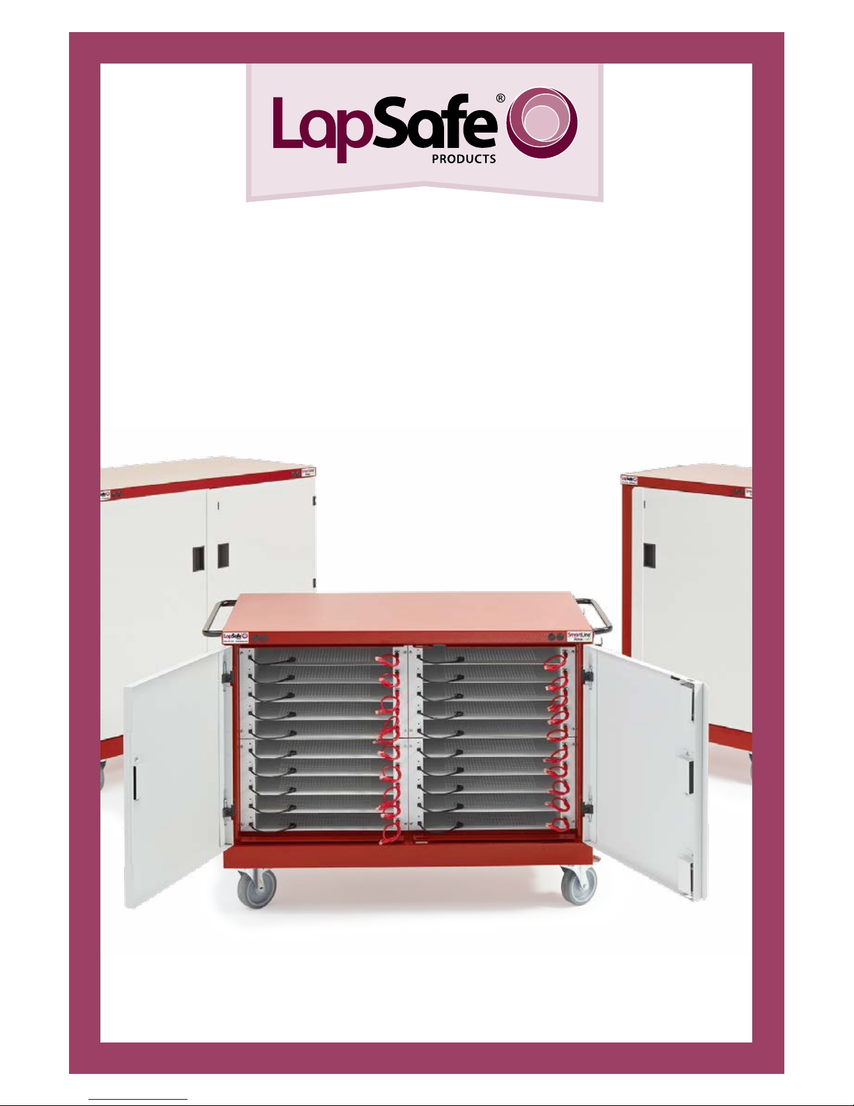
If your trolley is fitted with an alarm ensure that this is deactivated before moving
the trolley. (Figure 5)
• Check that the power has been turned o on the trolley and at the wall
socket.
• Carefully disconnect the mains power lead from the back of the trolley and
from the wall socket placing the power lead in the cable tidy located on one
of the trolley handles.
• Check that any network cable (Cat5) has been disconnected from the back of
the trolley.
• Ensure that all of the trolley doors are securely closed and locked, and that
all keys have been removed. Do not move the trolley with a key le in the
lock.
• Ensure that there are no items le on the top of the trolley.
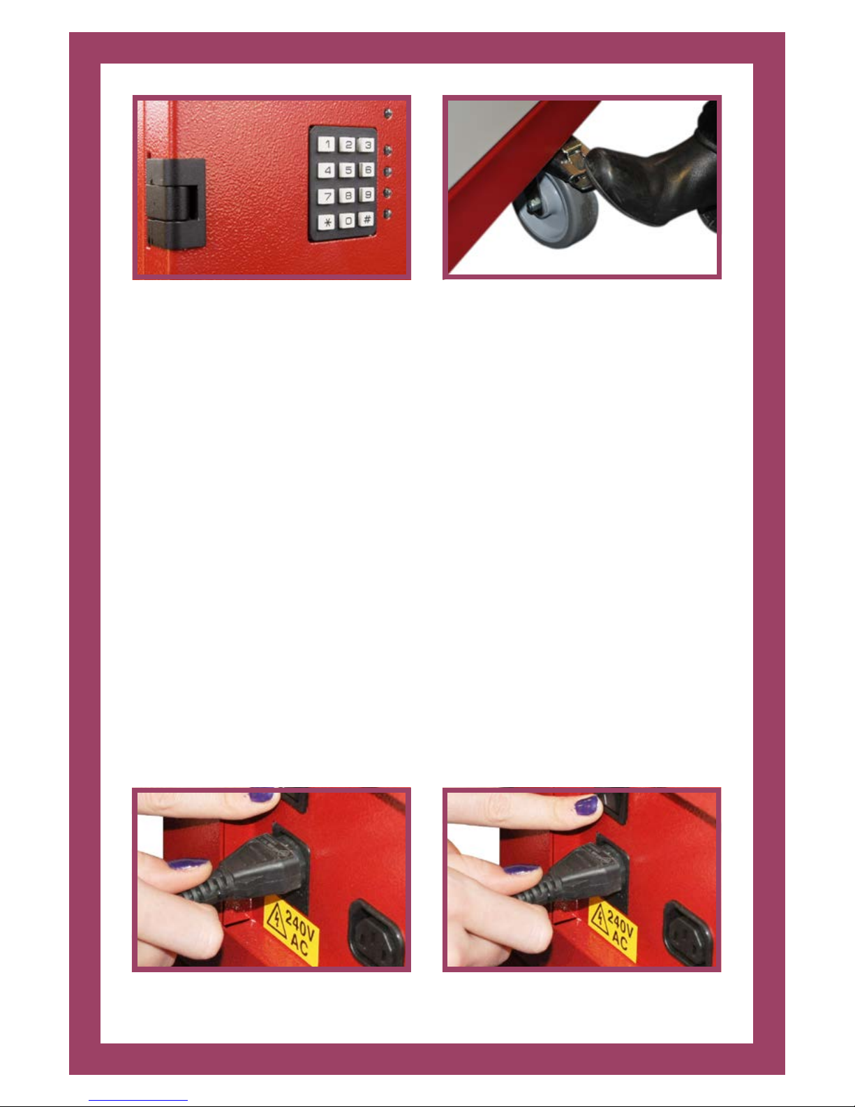
• Disengage wheel brakes using the foot operated pedals before moving the
trolley. (Figure 6)
• Special care should be taken on inclines.
At the new location
• Ensure that all wheel brakes are applied using foot operated pedals.
• Never position the trolley in front of any fire exit ot fire escape routes
• Never position the trolley in the view of any windows for security

7
Copyright LapSafe® Products
The Mentor™ Range - User Manual
Figure 5
Alarm
Figure 6
Wheel brake
5. Charging your devices
• Connect the mains power lead supplied with your trolley to the power port
near the bottom at the back of your trolley (Figure 7).
• Plug the pin end into a wall power socket and turn on at the wall.
• Turn on the power at the trolley by flipping the power switch next to the
power port (Figure 8).
Figure 7
Connecting power lead
Figure 8
Power switch

8
The Mentor™ Range - User Manual
Copyright LapSafe® Products
5.1. Charging devices - SmartLine™
If you have chosen SmartLine™ with PowaSave™ then your trolley has been fitted
with LapSafe®’s ultra-safe preconfigured charging leads, specific to the make and
model of your chosen device. You do not require the AC adaptors that come with
your devices to be fitted into this trolley. (Figure 9)
• Place each laptop into a charging bay – only one device per shelf unless
configured for netbooks where sometimes two per shelf can be
accommodated (in this case two charging leads will be visible)
• Plug the black SmartLine™ charging cables provided in each bay into the
corresponding laptop’s power port to allow charging (Figure 10)
Module charging lights explained
Figure 9
SmartLine™ module
Figure 10
Connecting SmartLine™ cable
Batteries
Charging
RED
Batteries 80%
charged
BLUE
Batteries
fully charged
and power is still
being provided
BLUE
flashing frequently
Batteries charged
and power
supply is on
standby
BLUE
flashing slowly
Checking laptops
for charge
request (every 60
minutes)
PURPLE
No laptop
connected
NO LIGHT

9
Copyright LapSafe® Products
The Mentor™ Range - User Manual
Figure 11
ChargeLine™ module
What is PowaSave™
PowaSave™ technology is designed to provide power savings over ‘duration
charging’ of laptops and netbooks.
This highly intelligent system is only available on the Mentor™ SmartLine™. It
automatically senses when a module (of five devices) is fully charged and it then
stops charging the module to avoid wasting power; thus making vast energy
savings.
All devices are still charged simultaneously in the fastest possible time.
5.2. Charging devices - ChargeLine™
If you have chosen ChargeLine™ then your trolley will be configured to allow you
to use the AC adaptors that are supplied with your device. Your trolley will have
either a three pin 13 amp socket fitted to each shelf or a European socket.
(Figure 11)
• Neatly place one AC adaptor into each charging bay and plug into the white
charging socket provided.
• Place one device onto each shelf and connect the corresponding AC adaptor
to each laptop.
Note
No power will be supplied to the devices until the front doors have been securely
closed – this is a safety feature to ensure no user comes into contact with mains
voltage.

10
The Mentor™ Range - User Manual
Copyright LapSafe® Products
Chassis charging lights explained
The trolley is in ‘standbymode’ – there
is power to the trolley but not to the
charging modules inside it. The
trolley will only begin charging once
the doors are closed and locked.
Once closed the RED will come on.
GREEN
Doors are shut and locked and there is
power to the charging modules inside
the trolley; if laptops are plugged in
they will be charging.
GREEN +RED
5.3. Charge & Sync
If you have purchased a Mentor™ Charge & Sync for tablets such as iPads, then
your trolley will allow you to charge the devices using their own USB cables and
allow the devices to be synchronised to a host MacBook or laptop. Your trolley will
be fitted with USB sockets in each bay.
Setting up the cable management
Step 1
Bunch up a USB cable
into a tidy bundle and
cable tie together.
Step 2
Plug the USB into the
socket in the Charge &
Sync Module
Step 3
Pass a cable tie
through the right hole
then back up through
the le.

11
Copyright LapSafe® Products
The Mentor™ Range - User Manual
Step 4
Tie up the bundle with the cable
tie and cut o the excess
Step 5
Complete steps 1-4 for each
charge & sync bay in your trolley
Module charging lights explain - basic function
The lights on the front of the charge and sync module explains which mode it is
in; sync and charge, charge and sync or auto cycles:
AMBER light o, GREEN light flashing slowly, and BLUE light on
– synchronising will commence once the devices are connected
to host laptop or MacBook. Charging will commence once the
synchronising has finished or timed out.
Note: If no host device is connected when the unit is switched on
charging will commence. (GREEN light o, AMBER light comes on
to indicate charge and will blink to confirm full charge).
Charge & sync push button modes
The black push button is found on the front of each module with the adjacent
mode lights and these can be set in various modes which override the default
mode as follows:-
‘All O’ mode
Pressing once aer power-up will select ‘All O’ mode.
AMBER and GREEN lights o, BLUE light blinking briefly = Power
on with no activity.
From the ‘All O’ mode, pressing the black button again will select
‘All Charge’ mode.

12
The Mentor™ Range - User Manual
Copyright LapSafe® Products
‘All Charge’ mode
Pressing twice aer power-up, will also select ‘All Charge’ mode.
BLUE and GREEN lights o, AMBER light flashing slowly - waiting
for iPads/tablets to be connected = charging on standby.
BLUE and GREEN lights o AMBER light solid = One or more
devices are charging.
BLUE and GREEN lights o AMBER light blinking briefly = All
connected devices are fully charged.
‘All Sync’ mode
Pressing three times aer power-up will also select ‘All Sync’ mode.
BLUE and AMBER lights o, GREEN light flashing slowly = sync
on standby waiting for devices and a host PC or laptop to be
connected
BLUE and AMBER lights o, GREEN light solid = syncing one or
more devices
BLUE and AMBER lights o, GREEN light blinking briefly = All
connected devices have synchronised for the preset period.
(Default is set to one hour, aer which the Mentor™ Charge and
Sync trolley will return each device to charge status to maintain
optimum readiness.
From the ‘All Sync’ mode, pressing the black button again, returns the module to
the default ‘Sync then Charge’ mode.

13
Copyright LapSafe® Products
The Mentor™ Range - User Manual
6. Mentor options
Printer
If you have a printer module built into your trolley please refer to your printer
manual for guidance on how to use the printer and to load and change the printer
cartridges.
The printer module has been connected into the trolley and once you have
connected the trolley to the mains power it will be ready to use.
If you wish to use your own printer housed on the top of the trolley a mains outlet
has been provided at the rear of the trolley and also a network socket (A network
socket is an option or standard with Data Transfer (DTM)). Care should be taken
when moving the trolley and on no circumstances should the trolley be moved
without disconnection of the power sockets and/or network connection. The
trolley should not be moved with the printer on the top of the unit.
Network connectivity
If your trolley features network connectivity, you can plug the trolley into your
network by connecting a standard network cable into one of the auxiliary points
on the back of the trolley.
Data transfer (DTM)
If your purchase includes DTM your trolley will be network ready (these are the
red network cables within your charging bays), you can update all of your laptops
simultaneously inside the trolley using Wake on LAN soware.
• Make sure that the trolley is connected to the network and switched on
• Plug each individual red DTM cable inside the trolley into the network
ports of each laptop and ensure that the trolley is switched on. If you have
a ChargeLine™ trolley (uses AC adaptors) close the trolley’s doors before
beginning the update.
• The laptops are now ready to receive updates

14
The Mentor™ Range - User Manual
Copyright LapSafe® Products
Figure 12
Connecting a network cable
Figure 13
Network connectivity
Docking station
If you have purchased a docking station with your trolley then please refer to the
docking station user guide to fit and dock correctly.
Timer
If your laptop trolley has been fitted to include a timer, please refer to the timer
user manual provided at the time of purchase.
7. Alarm
If your trolley is fitted with an alarm please note the following:
• The alarm’s internal back up battery will be disconnected upon delivery.
Open the rear service door with the keys provided and connect your battery
as shown. Once this step is completed please ensure your laptop trolley is
connected to mains power supply and powered on, and all the doors should
be shut and locked.
Note: it takes approximately 6 hours to fully charge the alarm battery.
• There are five LEDs on the right hand side of the keypad. When the trolley is
connected to a live power supply and all of the doors are locked, the trolley
will be ready to be alarmed and the LEDs will be:

15
Copyright LapSafe® Products
The Mentor™ Range - User Manual
1 ON (Green)
2 O
3 ON (Amber)
4 O
5 O
Changing authorised person pin
Upon delivery, your new trolley will have a default pin code of 1234. You will need
to change this to a new bespoke pin code so that you can access the system and
manage the issue of user pin codes.
If you make an error at any time, or you get timed out, enter * and start again
Enter 1234 into the keypad, there will be a series of bleeps. Enter 9 before they
stop.
All LEDs will flash, and then settle to indicate:
All LEDs will light up and within the next 10 seconds you need to:
Enter 1234 or your old pin code, then all LEDs will light up and within 10 seconds
you must enter your new four digit pin code. Bottom LEDs will go out one at a
time as numbers are entered, and as the last number is entered the LED display
will indicate: Enter *, LEDs will flash and settle down to:
1 ON (Green)
2 O
3 O
4 O
5 ON (Red)
1 ON (Green)
2 O
3 O
4 O
5 ON (Red)

16
The Mentor™ Range - User Manual
Copyright LapSafe® Products
Enter *, LEDs will flash and settle down to:
1 ON (Green)
2 O
3ON (Amber)
4 O
5 O
Activating the alarm
Enter your four digit pin code and you will hear a bleep for 10 seconds before the
alarm is set. The alarm will go o if the trolley is not finally positioned within 10
seconds. If the alarm has been set correctly, the bleeps will stop and the LEDs will
change to:
If the alarm has not been set correctly, there will only be two or three bleeps and
the LEDs will not change from their normal condition:
In such cases, check that all doors are properly locked, the power supply is on,
and try re-entering your pin code. If this should fail again, contact LapSafe®
Products.
1 ON (Green)
2 ON (Green)
3 O
4 O
5 O
1 ON (Green)
2 O
3 ON (Amber)
4 O
5 O

17
Copyright LapSafe® Products
The Mentor™ Range - User Manual
Deactivating the alarm
To deactivate the alarm system, enter your pin code into the keypad on the back
of the trolley and a single bleep will indicate that the alarm has been deactivated.
The LEDs will revert back to their normal configuration:
If the trolley has to be moved to gain access to the keypad, a bleep will sound
giving you 10 seconds to enter your pin code. Any longer and the alarm will
sound.
Alarm sounds
If the alarm should sound for no reason, enter your pin code and the alarm will
stop. In the unlikely event that it does not, evacuate the room, close the door and
contact your authorised person. Do not stay in the room with the alarm on; it is
very loud!
8. Trolley upgrades
The modular design of your Mentor™ means that as your needs change, you may
be able to upgrade or change the modules.
Possible upgrades are:
• Upgrade to accept new laptops/netbooks/other mobile ICT devices
• Add functionality (e.g. DTM, Wireless Access Point, docking station)
For all upgrades you will need your trolley’s serial number (found at the rear of
the trolley on a silver plate), then call the LapSafe® Support Team.
1 ON (Green)
2 O
3 ON (Amber)
4 O
5 O

18
The Mentor™ Range - User Manual
Copyright LapSafe® Products
9. Warranty
All Mentor™ trolleys come with a Lifetime Parts & Labour Warranty. To activate
your FREE Lifetime* Parts and Labour Warranty, please refer to the warranty
documentation inside your welcome pack or go on-line and register at
www.lapsafe.com/activate
10. Care and maintainance
Dos
• Lock your trolley when not in use
• Keep your keys in a safe place and not in the same room as the trolley
• Remember to set the alarm (if fitted)
• Read the Health and Safety guidelines in the user guide and share this
information with all users
• Activate your warranty at lapsafe.com/activate
• Unplug charging leads before taking laptops out of the trolley
Don’ts
• Do not move the trolley without disconnecting the mains power
• Do not move the trolley with the mains lead trailing use the cable tidy
• Do not leave keys in the doors locks when moving the trolley
• Do not remove doors
• Do not leave trolleys in the view of a window
• Do not try to modify the trolley in anyway without contacting LapSafe® first
to check that it is safe to do so

19
Copyright LapSafe® Products
The Mentor™ Range - User Manual
11. Health & Safety
All products manufactured by LapSafe® Products have been thoroughly tested
and certified by an authorised and INDEPENDENT testing house before sale.
Full CE compliance, which includes the requirements of LVD and EMC directives, is
a STANDARD FEATURE of any solution manufactured by LapSafe® Products, as are
many more built in safety features. CE Marking can be found on the product serial
number plate, usually at the lower rear of the cabinet. CE Declaration of
Conformity Certificate is issued with each product in the User Guide Pack.
Please be advised of the following safety advice:
At no time are the rear red service doors of the trolley to be opened by anyone
other than an authorised person.
At no time should anyone attempt to physically li the trolley, as this could cause
injury to the persons concerned and even damage to the trolley, which will
invaldate the manufacturer’s warranty. Should the movement of the trolley
require this type of action, you are advised to seek advice from the authorised
person. In such circumstances, the matter should be referred to LapSafe®
Products for consultation and advice.
• Always apply the wheel brakes when the trolley is either parked or not in use.
• Disconnect the mains supply and stow the mains cable into either the cable
• management provided or on top of the unit before moving
• Always ensure that the main power lead does not present a trip hazard when
connected to the mains.
• Always ensure that the main power lead is fully extended when connected to
the mains.
• The trolley should only be moved on horizontal surfaces.
• Always ensure that the trolley NEVER impedes full and free pedestrian access
to all fire routes, fire exits and normal access routes.
• Only place the approved laptops in the trolley for recharging.
• NEVER allow unauthorised access to the service doors at the rear of the unit.
• The above is not an exhaustive list. Contact LapSafe® Products should you
have any concerns.

20
The Mentor™ Range - User Manual
Copyright LapSafe® Products
12. Securing your trolley
In addition to the strong and robust build of the Mentor™ trolley there are two
levels of extra mechanical security that are provided as standard with the
Mentor™.
Security Loop
Welded to the underside of the chassis at the end of the unit there is a security
bracket (loop) which enables the trolley to be chained and/or padlocked to a fixed
location. Padlocks and chains are not provided.
Locks/Keys
The front access doors and the rear service doors have been reinforced to resist
attack and they have been fitted with high security locks. The keys to the front
and back doors are dierent, and two sets of keys are supplied for each door set
when the trolley is delivered.
Extra keys can be ordered at a small cost at www.lapsafe.com/keys you will need
the serial and key numbers at the time of your order.
Docking station
If you didn’t purchase an optional docking station with your trolley, we can still
provide one fully fitted to your Mentor™ to enable you to dock the trolley to a wall
for extra security. Please contact us on 0800 130 3456 for more information.
This manual suits for next models
6
Table of contents
Other LapSafe Batteries Charger manuals