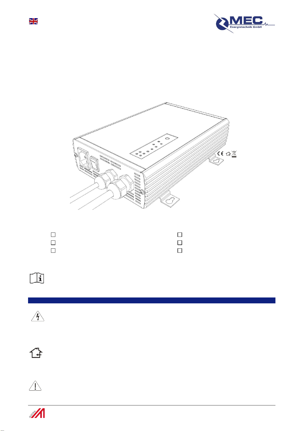
MEC-Energietechnik GmbH Instruction manual ProTask-360SR
Vers.: 2.1-2015 3 / 4 www.mec-energietechnik.com
5. Start up the charger and choice of charging profile
Before operating please make sure that the power cable and the charger including the charging cable show no damages!
Please consider the charging instructions from the battery manufacturer before charging.
A) Connecting and charging of the battery
Make sure that, the charger is switched off.
Connect the Charger with the power grid.
Connect the temperature sensor to the battery, the sensor position at the battery is manufacturer specific.
Connect the drive-inhibit to your application. Note: If the drive-inhibit is not used, there are no effects relating to the charging process.
Switch on the charger. **)
Choose an adequate charge profile for the battery to be charged –choice of charging profiles see point B.**)
Switch off the charger.**)
Connect the charging cable to the battery –make sure that the polarity is correct!
Switch on the charger - the charger is starting the charging process automatically.
B) Choice of charging profiles and power supply mode
The LED of the active charging profile lights permanently after starting the charger. In power supply mode, all 4 program selection
LEDs are lighting permanently.
To change the charging profile push the (“Press“) button permanently. The LED is flashing slowly and changes to fast blinking after 5
seconds.
Now you are able to change the charge profil by pushing the button (“Press“) briefly. The respective charging profile is signaled by the
respective charging profile-LED. The power supply mode is shown as active by permanent lighting of all 4 program selection LEDs.
If the correct charge profile is chosen, confirm the choice by pressing the (“Press“) button for 5 seconds again.The charge profile LED
changes from blinking to continuously on.
The active charging profile (power supply mode) remains active also after disconnecting from power grid.**)
A changing of the charging profiles is also possible during an active charging process. The charger automatically
starts after changing the charging profile a new charging process.**)
**) only valid for multi-profile charger
6. Charging the battery
After connecting the battery correctly and starting the charger, the charging process starts automatically and runs through the following
five charging phases:
1st charing phase: recovery
This charging step is indicated by blinking of the Charge-LED (4) and Full-LED (5).
Explanation: The recovery phase starts automatically at deeply discharged. The battery-voltage get lifted up to a loadable level by
using 70 controlled voltage pulses and the charger switches over to the second charging phase. If the voltage level is not enough, the
charging process is canceled because there is a wrong (<12V) or defect battery connected
2nd charging phase: soft start
This charging step is indicated by constant lighting of the Charge-LED (4).
Explanation: The charger reduces charging current, in order to extend battery lifetime.
3rd charging phase: constant current
This charging step is indicated by slow blinking of the Charge-LED (4).
Explanation: During the constant current phase, the battery is being charged up to ~80% of its capacity.
4th charging phase: constant voltage
This charging step is indicated by quick blinking of the Charge-LED (4).
Explanation: During the constant voltage phase the battery is being charged to its maximum capacity.
5th charging phase: trickle charging
This charging step is indicated by constant lighting of the Full-LED (5).
Explanation: After the 4th charging phase the battery is completely charged. Now the battery is charged with reduced voltage and
reduced charging current in order that the state of charge remains after finishing the charging process. If the battery stays connected to
the charger in this mode, an automatic charging restart results to care the battery after 15 days.
Disconnecting the charger from the battery:
Switch off the charger.
Disconnect the charger from the battery.
Recommend battery sizes