Larin METS-1 User manual

Model# METS-1 Mobile Engine Testing Station
Owner’s Manual
Copyright© 2022 by Larin Corp. All rights reserved. No portion of this manual or any artwork contained herein may be reproduced in
any shape or form without the express written consent of Larin Corp. Diagrams within this manual may not be drawn proportionally.
Due to continuing improvements, actual product may dier slightly from the product described herein. Tools required for assembly
and service may not be included.
IMPORTANT: Please keep your receipt in a safe, easy to nd location, as you will need it for any warranty/repair issues that may
arise.
Read all instructions and safety warnings before using this product. Failure to follow the instructions and safety warnings
may result in personal injury or property damage.
For Customer Service please email to serv[email protected] or call 1-800-87-LARIN (1-800-875-2746)
Monday – Friday 8:00am to 4:30pm PST
WARNING
Engine Not Included

Page 2
WARNING
!
!
GENERAL SAFETY RULES
CAUTION: Do not allow persons to operate or assemble this product until they have read this manual and have devel-
oped a thorough understanding of how it works.
WARNING: e warnings, cautions, and instructions discussed in this instruction manual cannot cover all possible
conditions or situations that could occur. It must be understood by the operator/user that common sense and caution
are factors which cannot be built into this product, but must be supplied by the operator/user.
SPECIFICATIONS
Max. Load Capacity: 1000 lb
Dimensions: 46”L x 32.5”W x 37”H
Fuel Tank Size: 1 gallon
1. Study, understand, and follow all instructions before operating this device.
2. Use only on hard, level surface.
3. Do NOT exceed the rated capacity of 1,000lbs for this product.
4. Any Engine Station that appears to be damaged in any way, is found to be worn, or operates abnormally shall be
removed from service immediately until repaired.
5. If it is believed that the Engine has been subjected to abnormal load, or shock, it shall be removed from service
immediately until fully inspected.
6. Assure load is centered and secured to mounting attachments before moving or testing. O-center loads may make
the load unstable.
7. Because of potential hazards associated with this type of product,
NO alterations shall be made to the product.
8. Following safety rules of gasoline use.
8. Only attachments and/or adapters supplied by the manufacturer shall be used.
9. Use caution when making all of the connections.
10. Follow engine testing procedures and precautions as specied by the engine manufacturer’s owner’s/repair manual.
11.Failure to heed these markings/warnings may result in personal injury and/or property damage.
ASSEMBLED

Page 3
PARTS LIST AND DIAGRAM
Note: Some parts listed and shown are
for illustration purposes only, may not be
available as replacement parts.
Part # Description Qty Part # Description Qty
1 Le Side Frame Tube (B) 1 19 Fuel Tank Strap 2
2 Right Side Frame Tube (C) 1 20 Fuel Tank 1
3 Rear End Frame Tube 1 21 Support Strap 2
4 Cross Member Frame Tube 2 22 Nut M12 2
5 Front End Frame Tube (E) 1 23 Flat Washer d12 4
6 Swivel Caster 2 24 Spring Washer d12 2
7 Rigid Caster 2 25 Nut M8 8
8Sleeve 2 26 Flat Washer d 8 28
9 Black Sleeve with Post 4 27 Spring Washer d 8 8
10 readed Rod 2 28 Bolt M8 X 20 8
11 Tray 1 29 Bolt M8 X 65 10
12 Tray Support 1 30 Locknut M8 20
13 Long Vertical Post 2 31 Bolt M8 X 50 10
14 Dash Panel/Gauges 1 32 Bolt M10 X 65 2
15 Short Vertical Post 2 33 Flat Washer D10 2
16 Horizontal Bar 1 34 Locknut M10 2
17 Engine Support Strap 2 35 Inlet Water Adapter 1
18 Engine Support 2 36 Outlet Water Adapter 1
1 ignition key switch , 4 position, 12v
Gauges: size 52mm, 12v
1 oil pressure
1 oil/water temperature
1 tachometer

Page 4
ASSEMBLY INSTRUCTIONS
Tools Needed for Assembly:
Crescent Wrench, Phillips Screwdriver, 13mm Wrench, 14mm Wrench, 17mm Wrench, 19mm Wrench
For all of the following steps, please refer to Parts Diagram, Parts List and Illustrations.
STEP 1 Unpack Testing Station and verify that you have received all of the parts as indicated on the parts list.
STEP 2 Place Le Side Frame Tube B Part # 1 and Right
Side Frame C Part# 2 on the oor with the 6 holes on the
top. Make sure that the holes are closer to the outer edge
of the metal parts and that the two holes on the sides are
closer to the top than to the bottom. See Illustration A.
STEP 3 Attach Swivel Casters (#6) to Front
End Frame Tube E (#5) using four of the
M8x20 bolts (#28),Flat washers(#26),Spring
washers(#27), and M8 nut(#25). two for each
caster. See Illustration 1.
STEP 4 Attach Rigid Casters (#7) to Rear
End Frame Tube (#3) using four of the M8x20
bolts (#28),Flat washers (#26),Spring wash-
ers(#27), and M8 nuts(#25). two for each
caster. See Illustration 2.

Page 5
STEP 5 Place Cross Member Frame Tube
(#4) on the oor. Slide the Black Sleeve with
Post (#9) onto the Cross Member Frame Tube
(#4). Next slide another Black Sleeve with Post
(#9) onto the Cross Member Frame Tube (#4).
Next insert the Sleeve (#8) into the end of
Cross Member Frame Tube (#4) as shown in
Illustration 3.
STEP 6 Slide Cross Member Frame Tube
(#4) onto Le and Right Side Frame Tubes
B,C (#1 and #2). Next slide the other
Cross Member Frame Tube (#4) onto the
Le and Right Side Frame Tubes B, C (#1
and #2) as shown in Illustration 4.
STEP 7 Slide the readed Rods ( #10 ) through D12 Flat Washer (#23), Front End Frame Tube E (#5) into the ends of Le and
Right Side Frame Tubes (#1 and #2). Make sure it is the side that has three holes and all holes are on top area of the tubes.
See Illustration 5.
Make sure marker B on Le Side Frame Part# 1 meets with marker B on the Front End
Frame Tube (E) Part # 5, marker C on Right Side Frame Part# 2 meets with C on Part 5. See
Illustration 5.1 below.
STEP 8 Place Rear End Frame Tube (#3) onto the
ends of the readed Rods (#10) at the opposite
end of Le and Right Side Frame Tubes (#1 and
#2). Fasten with M12 nut D12 Flat Washer (#23)
and D12 Spring washer (#24). See Illustration 5.
STEP 9 Using M8x65 bolt (#29), attach Swivel
Casters (#6) to Le and Right Side Frame Tubes
(#1 and #2). Fasten with M8 Locknut (#30) , and
D8 Flat Washer (#26). Next, also using the long
bolt (#29), attach Rigid Casters (#7) to Le and
Right Side Frame Tubes (#1 and #2) on opposite
end. Fasten with M8 Locknut (#30) , and D8 Flat
Washer (#26) . See Illustration 5.
C
B
Illustration 5
Illustration 5.1

Page 6
STEP 10 Place the Long Vertical Posts (#13) onto the vertical posts on the Front End Frame Tube (#5). Attach the Support Straps
(#21) to the Le and Right Side Frame Tubes (#1 and #2) using the M8x65 bolts (#29) , D8 Flat Washers (#26) and M8 Locknut
(#30) . See Illustration 6.
STEP 11 Place the remaining Short Vertical Posts (#15) over the vertical posts of the attached Black Sleeves with Posts (#9). Attach
with M8x50 bolts (#31) , D8 Flat Washers (#26) and M8 Locknut (#30). See Illustration 6.
STEP 12 Place two of the Engine Support (#18) onto vertical posts of the attached Black Sleeves with Posts (#9). Attach with
M8x50 bolts (#31) , D8 Flat Washers(#26) and M8 Locknut (#30). See Illustration 6.
STEP 13 Attach Tray Support (#12) to Le and Right Side Frame Tube (#1 and #2) using long bolts (#35). Place Tray (#11) on top
of Tray Support (#12) and Front End Frame Tube (#5). See Illustration 6.
STEP 15 Place Dash Panel (#14) on top
of Long Vertical Posts (#13). Attach with
M8x65 bolts (#29) , D8 Flat Washers (#26)
and M8 Locknut (#30) . See Illustration 7
STEP 14 Place Horizontal Bar (#16) on top
of Short Vertical Posts (#15). Attach with
M8x65 bolts (#29) ,D8 Flat Washers (#26)
and M8 Locknut (#30) . See Illustration 7.

Page 7
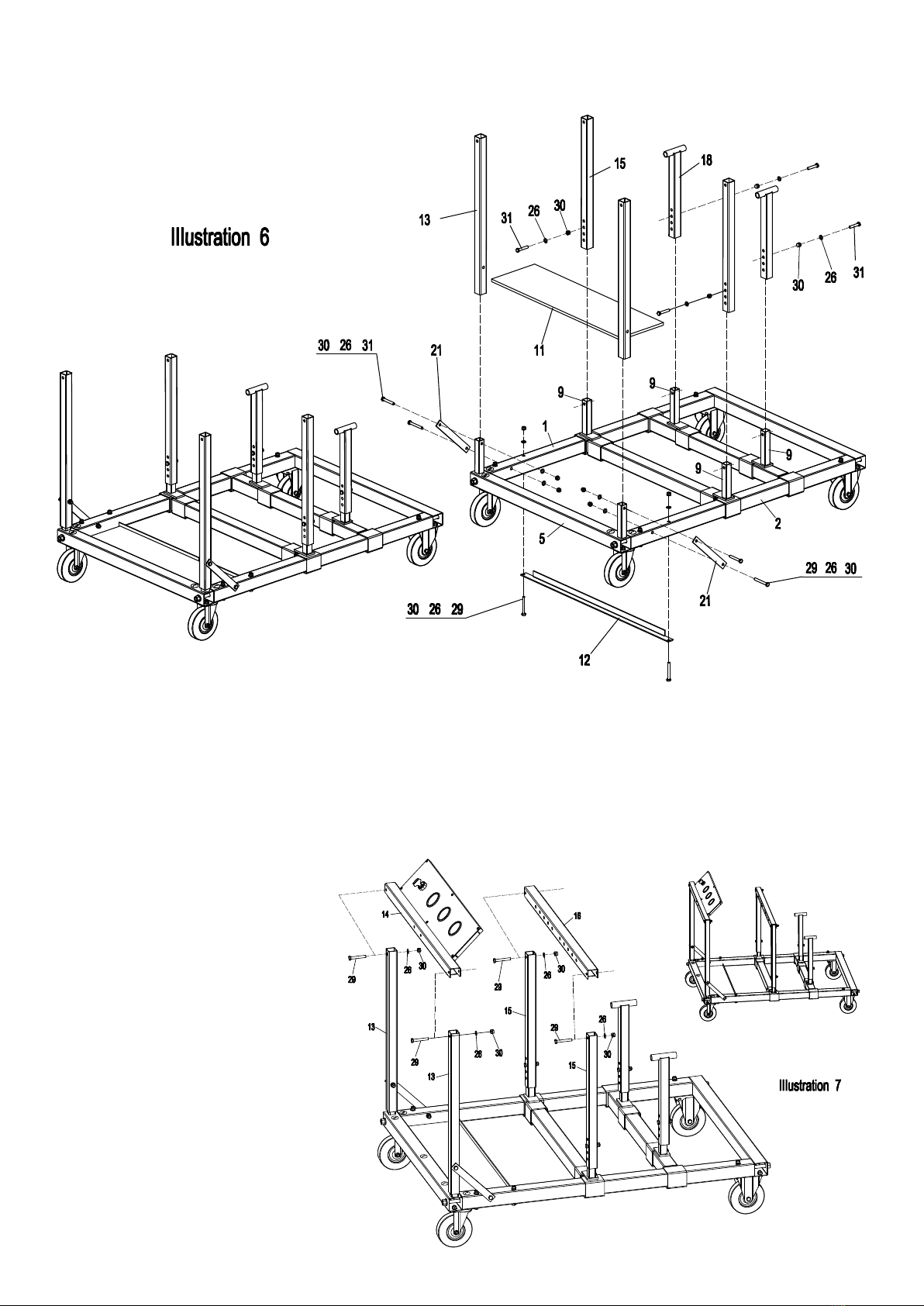
STEP 16 Place Engine Support
Strap (#17) onto Horizontal Bar
(#16). Attach with M10x65 bolt
(#32) , D10 Flat Washer (#33) ,
M10 Locknut (#34) .
See Illustration 8.
STEP 17 Slide Fuel Tank (#20)
into Fuel Tank Straps (#19).
Attach Fuel Tank Straps (#19) and
Dash Panel (#14) using M8x65
bolts (#29), D8 Flat Washer (#26)
and M8 Locknut .
See Illustration 8.
DIRECTIONS FOR USE
Use Precautions
Failure to heed these instructions may result in personal injury and/or property damage:
1. Study, understand, and follow all instructions before operating this device. Use as intended only.
2. Do not exceed rated capacity. Be aware of dynamic loading! Sudden load movement may briey create excess load causing
Product failure.
3. Use only on hard, level surfaces. Surfaces must be dry, clean and free from oil or grease.
4. Lock and chock wheels before applying a load.
5. Assure load is centered and secured to mounting attachments.
6. Wear ANSI-approved safety goggles and heavy-duty work gloves during use.
10. Inspect before every use, do not use if parts loose or damaged.
11. is product is not a toy. Do not allow children to play with or near this item.
12. Check and clean fuel tank before each use.
13. Secure the engine to the Testing Station as instructed.
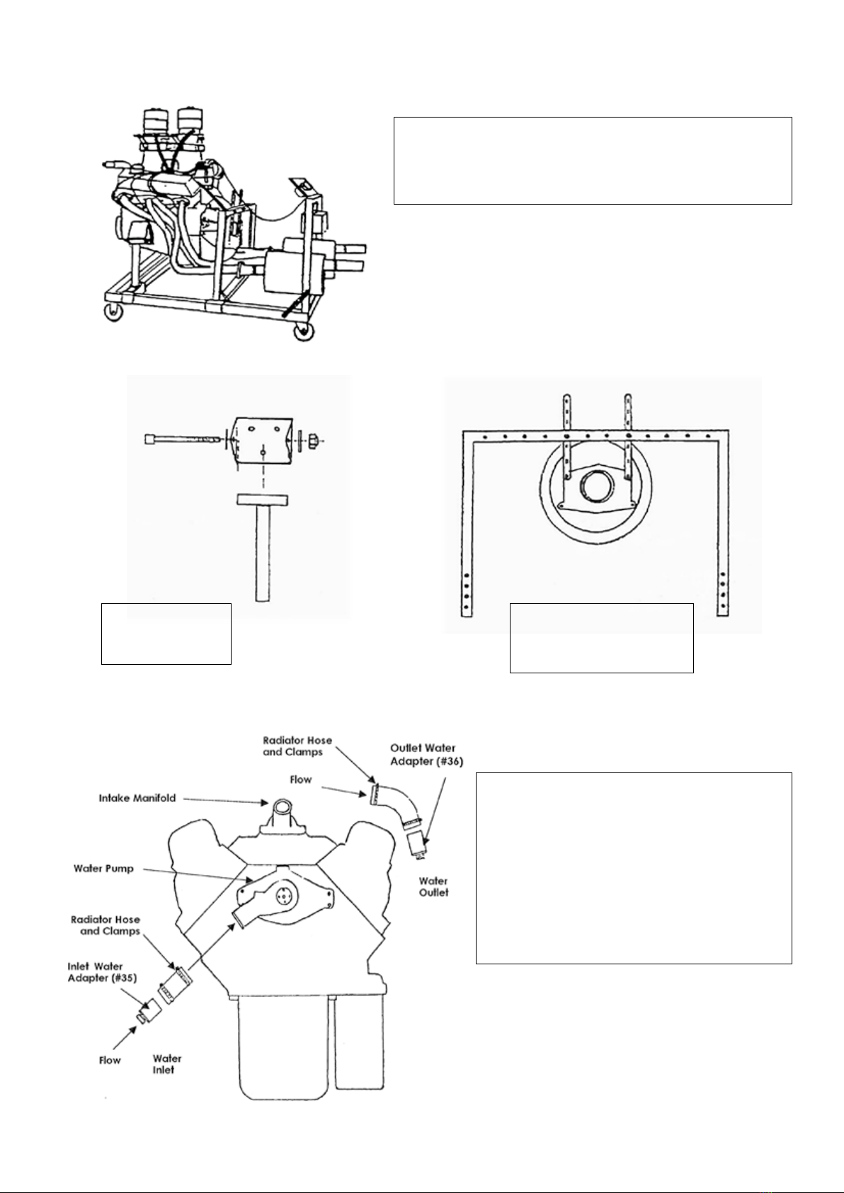
Mounting Engine
TO PREVENT SERIOUS INJURY:
Before attaching an engine to the stand, conrm that its weight does not exceed the Stand maximum capacity.
1. Determine the thread type and length of bolts (not included) needed to thread into the engine block.
2. Align the Engine Supports and Straps part# 17 and 18 with four mounting bolt locations on the engine.
3. Place the bolts (not included) through engine supports and straps and securely tighten them into the engine.
7. Slowly lower the hoist/engine crane (sold separately) until all the engine’s weight is held by the stand.
8. Safely release the engine from the hoist/engine crane.
Removing Engine
Secure the engine properly to the crane. Use the crane to support all of the engine’s weight directly overhead, once the
engine is properly supported by the crane, remove the bolts securing the Engine Supports and Straps Part# 18/17 to
the engine.
Helpful using tips refer to Figure 1, 2, 3.
ASSEMBLED

Page 8
Small block Chevrolet header (73 pickup)
Turbo muers with 2”dia x 6”length tubes on each side of muers.
Engines can be placed in this manner or sideways or backwards on
stand.
REAR
Engine mounting straps, using
last boltholes on straps to attach
bell housing to bow.
FRONT
Factory motor mount
pockets most engines.
ENGINE MOUNTING
FIGURE 1
FIGURE 2
Attach home sized garden hoses to water adapters.
ermostat is NOT used, and the water pump remains
stationary (not spinning). It is important to run the
water in the correct direction, otherwise hot spots may
occur inside the engine and possible damage. Start with
a small amount of water. Watch the temperature gauge,
regulate to 160, 170, 180, as necessary.
Turn water o IMMEDIATELY upon turning the
engine o. us, eliminating the risk of cracking the
hot block or heads with cold water entering the engine.
Let engine cool down by itself.

Page 9
WIRING SYSTEM
NOTE
Ballast resister cuts battery voltage down to
about 7 volts for long point life. If you need 12
volts either eliminate or bypass resister.
NOTE
Most parts houses have in line universal type
fuel pumps that are about the size of an in line
fuel lter and make for a nice installation.
NOTE
Use radiator hose clamps to clamp fuel pump,
coils and ballast resister to the legs of the bow
under the panel with weather stripping in
between the two.
FIGURE 3
Keyed Positions 12 v ACC-OFF-IGN-START
ACC
OFF
ON
ST
Position
Terminal
Clockwise
1 (B) 2 3 4

Page 10
LARIN CORP. Warrants to the original purchaser that this product is free from defects in materials
and workmanship for the period of 90 days from the date of purchase. is warranty does not apply to
damage due directly or indirectly, to misuse, abuse, negligence or accidents, repairs or alterations outside
our facilities, criminal activity, improper installation, normal wear and tear, or to lack of maintenance. We
shall in no event be liable for death, injuries to persons or property, or for incidental, contingent, special
or consequential damages arising from the use of our product. Some states do not allow the exclusion or
limitation of incidental or consequential damages, so the above limitation of exclusion may not apply to
you. is warranty is expressly in lieu of all other warranties, express or implied, including the warranties of
merchantability and tness.
For warranty service, the product or part must be returned to us with transportation charges prepaid along
with Proof of purchase, and an explanation of the complaint. If our inspection veries the defect, we will
either repair or replace the product at our election or we may elect to refund the purchase price if we cannot
readily and quickly provide you with a replacement. We will return repaired products at our expense, but if
we determine there is no defect, or that the defect resulted from causes not within the scope of our warranty,
then you must bear the cost of returning the product.
is warranty gives you specic legal rights and you may also have other rights which vary from state to state.
LIMITED NINETY DAYS WARRANTY
For warranty service, please return the product prepaid to
Larin Corporation
5651 Schaefer Avenue,
Chino, California 91710.
Email: service@larincorp.com
Be certain to include your name and address, email address, proof
of purchase date and description of the problem.
NOTE
e diagrams and directions are for reference only, please consult a ASE qualied auto technician for correct installation.
Other manuals for METS-1
1
Table of contents
Other Larin Test Equipment manuals