Besantek BST-CHK01 User manual

Index Page
1. Warning and safety.............................................. 1
2. Specication ....................................................... 2
3. Safety notes........................................................ 3
4. Checking a RCD test.......................................... 4-6
5. Checking an installation or insulation tester........ 6-10
Checking for the correct applied
test voltage...................................................... 6-7
Checking the reading accuracy....................... 7
Checking the continuity measurement……..... 8-9
Checking for the AC voltage measurement
function........................................................... 9-10
6. Checking a LOOP tester…...............................… 11-12
7. Limited warranty….............................................. 12-13
Due to our policy of constant improvement and development,
we reserve the right to change specications without notice.

1. Warnings and safety
&IMPORTANT NOTE:
-1-

-2-
2. Specication
RCD Testing
Range
10mA±4mA Trip,14mA↑ over,150mS±10%
30mA±12mA Trip,42mA↑ over,150mS±10%
150mA±60mA Trip,210mA↑ over,30mS±10%
Insulation Testing
Range 1MΩ / 9.9MΩ / 99MΩ
Accuracy ± 1%
Max. Testing 1.2kV
Continuity Testing
Range 0.5Ω / 2Ω / 10Ω
Accuracy ± 0.05Ω / ± 0.1Ω / ± 0.2 Ω
Max. Current 300mA
LOOP Testing
Range Supply Loop / Supply Loop + 1Ω
Accuracy 0.45Ω ± 0.05Ω / 1.45Ω ± 0.05Ω
99 Washington Street
Melrose, MA 02176
Phone 781-665-1400
Toll Free 1-800-517-8431
Visit us at www.TestEquipmentDepot.com

3. Safety notes
4.
N
& IMPORTANT NOTE:
-3-

-4-
4. Check RCD tester
A. CHECKING A RCD TESTER
RCD tester simulates a current between live and earth to trip
TEST BOX.
The disconnect time of relay is shown on RCD tester usually in
milli-seconds if TEST BOX and RCD tester select the correct
current and the correct time range.
Generally, the tester has several current ranges plus a ‘5l’
function which multiplies the current range set by 5.
As switches can switch off, it is important to check more than
one current range. Leaving the instrument on the same range
in every check.
If too much current is induced into the tester, the RCD will TRIP.
For example, If you are checking a circuit which should have a
30mA RCD and the faulty range of your tester is on the 300mA
range, this will open any trip up to 300mA.
Test with both a long and a short trip time to ensure that it is
correct. It is less important if the tester has a ‘positive/negative’
cycle switch. This will be better for timing measurement.
The unique features of the electronic trip of TEST BOX allow
all the above to be tested quickly and easily. Accurate timing
is ensured as the time period is not dependant on the current
transition and an over-current LED can be lit. The positive/
negative switch can be checked, as the time period will be
10mS longer than starting on the negative cycle.
If the TEST BOX RCD is "TRIPPED", it is almost no check the
correct operation of the tester. There is no indication of over
current and the timing accuracy is poor need to change current
range on the tester.

lg!
.
·G
_q:�.
-5-

E.
0, o, .
. J,
-6-

-7-
Select the lowest test voltage (100V or 250V) range on the
tester. Press the “test” button on the tester. Note the voltage
LED (100V or 250V) on the TEST BOX. It should be lit with the
same range on the tester. Record the reading on the tester.
Repeat the same step on the other test voltage ranges.
NOTE: FOR THE LEDS TO BE PROPERLY LIT ON THE
TEST BOX, THE RED TERMINAL MUST BE
POSITIVE.ON SOME TESTERS THE RED LEAD IS
NEGATIVE, THE LEADS MUST BE REVERSE.
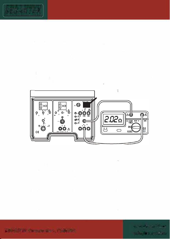
B. CHECKING THE READING ACCURACY
Connect the tester to the 1M terminal on the TEST BOX as
shown above. Start with the lowest voltage range and record
the reading on the tester. Allow from 0.99 MΩ to 1.01 MΩ,
± 0.01MΩ.
Connect the tester to the 9.9M terminal on the TEST BOX.
Select the 500V test voltage range and record the reading on
the tester. Allow from 9.8 MΩ to 10.0 MΩ, ± 0.05MΩ.
Connect the tester to the 99M terminal on the TEST BOX.
Select the 1KV test voltage range and record the reading on
the tester.
Allow from 98 MΩ to 100 MΩ, ± 0.5MΩ.
Common Problems Solution
Only the lower Test
Voltage LED lit Low battery.
Tester reads over
range all the time
Test leads open circuit. Note some
testers require using the correct test
leads.
Test Voltage LEDs
do not light up
A: TEST BOX not plugged in.
B: Tester faulty or low battery.
C: Test leads open circuit, try to
short tester leads together and
check zero.
D: Try to reverse test leads.


-9-
Select the tting range on the tester in order to read precise
measurement from each range on the tester.
For example, if the tester has a 200Ω, 20Ω and 2Ω ranges.
Use the 200Ω range to measure “10Ω”, the 20Ω to measure “2Ω”
and the 2Ω to measure “0.5Ω”.
Common Problems Solution
Reading unstable Check connections are clean and
tight in the sockets.
Reading high
Poor leads will give a high zero.
Check tester is zeroed correctly with
leads shorted together.
Tester reads over range
The test leads are open circuit. Note
some test leads are fused and some
use special connectors. Check leads
are OK.
D. CHECKING FOR THE AC VOLTAGE MEASUREMENT
FUNCTION
Some multi-function, insulation and installation testers can
measure AC voltage.
WARNING: MAIN AC OUTPUT VOLTAGE IS PRESENT
DURING THIS TEST AND WATCH OUT FOR AVOIDING
ELECTRIC SHOCK.
99 Washington Street
Melrose, MA 02176
Phone 781-665-1400
Toll Free 1-800-517-8431
Visit us at www.TestEquipmentDepot.com

9 l ;t
0, 0-t.
Q ·@
,�
({
.�
,!' &
O·
l23DVI:
6 a

9 � ,;' &
1.'70 0 O· 99
·@· ·0 @·
:@ :,� �

-12-
Common Problems Solution
Supply trips out when test
button pressed
TEST BOX must plug into
unprotected supply.
No power to Loop Tester
A: Faulty loop tester main supply.
B: TEST BOX does not plugged into
AC supply.
No reading on tester
Noise on main supply. Try a
different main Socket for the TEST
BOX.
7. Limited warranty
We warrant the product manufactured by us to be free from
defective material or factory workmanship and agree to repair
or replace this product which, under normal use and service,
disclose the defect to be the fault of our manufacturing, with no
charge for parts and service.
If we are unable to repair or replace this product, we will make a
full refund of the purchase price.
Consult the user's manual for proper instruction regarding use of
this instrument.
Our obligation under this warranty is limited to repairing, replacing
or making refund of this test equipment which proves to be
defective within twelve months from the date of original purchase.
This warranty does not apply to any of our products which have
been repaired or altered by unauthorized persons in any way
so as, in our sole judgment, to injure their stability or reliability,
or which have been subject to misuse, abuse, misapplication,
negligence or accident or which have had the serial numbers
altered, defaced or removed.
Accessories of this instrument are not our manufactures, which is
not covered by this warranty.

-13-
All warranties implied by law are hereby limited to a period
of twenty four months, and the provisions of the warranty are
expressly in lieu of any other warranties expressed or implied.
The purchaser agrees to assume all liability for any damages
or bodily injury which may result from the use or misuse of the
product by the purchaser, or its user, his employees, or others,
and the remedies provided for in this warranty are expressly
in lieu of any other liability we may have including incidental or
consequential damages.
We reserve the right to discontinue models at any time, or change
specication, price or design, without notice and without incurring
any obligation.
99 Washington Street
Melrose, MA 02176
Phone 781-665-1400
Toll Free 1-800-517-8431
Visit us at www.TestEquipmentDepot.com
Table of contents
Other Besantek Test Equipment manuals

Besantek
Besantek BST-ELC06 User manual

Besantek
Besantek BST-ET14 User manual

Besantek
Besantek BST-IT30 User manual

Besantek
Besantek BST-LT05 User manual

Besantek
Besantek BST-GFL31 User manual

Besantek
Besantek BST-ET16 User manual

Besantek
Besantek BST-MT298 User manual

Besantek
Besantek BST-IT705 User manual

Besantek
Besantek BST-LAN10 User manual

Besantek
Besantek BST-ELC01 User manual