Hioki HiLogger 3145-20 User manual

NOISE HiLOGGER
MEASUREMENT GUIDE
3145-20
Read first.
Offers an introduction to the 3145-20
NOISE HiLOGGER's basic measuring
method for first time users.


Contents
i
1
2
3
4
5
6
7
8
9
A
Index
Contents
Introduction __________________________________ 1
Verifying Package Contents _________________ 3
Preparing the Measuring Instrument ________ 4
Checking Noise on the Monitor Display _____ 8
View/Save Noise Progression ______________10
Noise Suppression __________________________18
Measurement Hints _________________________19
Sound Alarm When Exceeding Specified Value .................19
Specifying Recording Time .................................................22
Attaching an Event Marker to a Waveform .........................22

Contents
ii

Introduction
1
Thank you for purchasing the HIOKI "Model 3145-20 NOISE HiLOG-
GER." To obtain maximum performance from the instrument, please
read this manual first, and keep it handy for future reference.
The following instruction manuals are included with the 3145-20 NOISE
HiLOGGER. Refer to them as they pertain to your usage of the instru-
ment.
Introduction
Manual Content
1Measurement Guide
(this manual)
Read first.
Offers an introduction to the 3145-
20's basic measuring method for first
time users.
2Instruction Manual Contains explanation and instructions
regarding the instrument's operating
method and functions.
CD Content
3"DATA VIEWER for
3145"
Instruction Manual
Contains information about PC soft-
ware which can analyze the measure-
ment data recorded by the
instrument.
4"Communications"
Instruction Manual
Explainsthecommunicationfunctions
which can be used via the LAN and
RS-232C interfaces.
5"Communication
Commands"
Instruction Manual
Explains the commands for remote
control of the instrument via the LAN
and RS-232C interfaces.
Before reading this manual, fully read and understand "Safety Informa-
tion" and "Chapter 2 Measurement Preparations" in the instruction man-
ual, and then start taking measurements.

Introduction
2
Safety
Symbols The following symbols in this manual indicate the relative importance of
cautions and warnings.
Others
Notation
Indicates that incorrect operation presents an extreme
hazard that could result in serious injury or death to the
user.
Indicates that incorrect operation presents a significant
hazard that could result in serious injury or death to the
user.
Indicates that incorrect operation presents a possibility
of injury to the user or damage to the instrument.
Indicates advisory items related to performance or cor-
rect operation of the instrument.
( ⇒p. ) Indicates the location of reference information.
Indicates quick references for operation and remedies
for troubleshooting.
*Indicates that descriptive information is provided below.

Verifying Package Contents
3
Please check to make sure that no items are missing from your package.
Options
Model 9754 CLAMP ON NOISE SENSOR
Model 9418-15 AC ADAPTER
Model 9447 BATTERY PACK (7.2 V, 2400 mAh)
Model 9643 CHARGE STAND (For the 9447 BATTERY PACK)
Model 9612 RS-232C CABLE
(9-pin mini DIN to 9-pin Dsub, cross cable, for PC)
Model 9721 RS-232C CABLE
(9-pin mini DIN to 9-pin Dsub, straight cable, for modem)
Model 9726 PC CARD 128M
Model 9727 PC CARD 256M
Model 9728 PC CARD 512M
Model 9729 PC CARD 1G
Model 9642 LAN CABLE
Verifying Package Contents
Carrying case........................................1
Strap......................................................1
CD (Software, Instruction Manuals)
...................................................................1
Instruction Manual / Measurement Guide
(this manual) .............................each one
• "DATA VIEWER for 3145" Softwar
e
and Instruction Manual
• "Communications”
Instruction Manual
• "Communication Commands"
Instruction Manual
Model 3145-20 NOISE HiLOGGER...... 1
Accessories
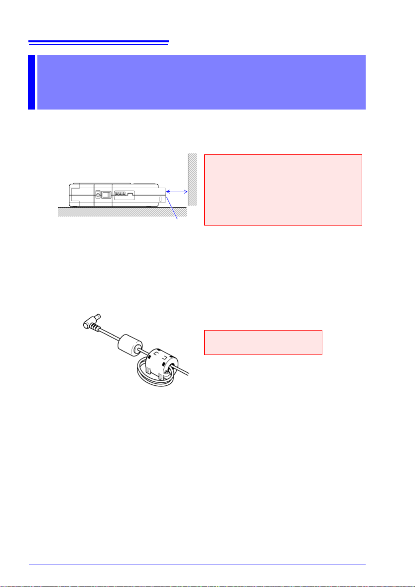
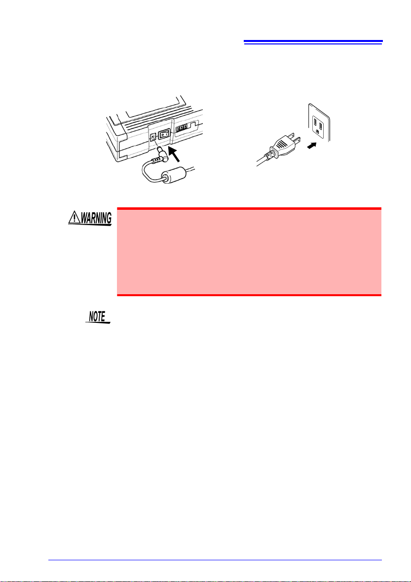
Model 9418-15 AC ADAPTER...............1
Ferrite cores ..........................................3

Preparing the Measuring Instrument
4
1. Install the instrument.
2. Install the included ferrite cores on the AC adapter and the Clamp on Noise
Sensor
Loop the output side of the cable through the ferrite core twice and then close
it until you hear a snap.
Preparing the Measuring
Instrument
10 cm or more
Ventilation holes
• Vents must not be obstructed.
• The instrument should be operated
only with the bottom side down-
wards.
• Do not place on an unstable stand or
on an incline.
(AC adapter shown here)
Install as close as possible to
the pre-installed ferrite core.

Preparing the Measuring Instrument
5
3. Connect the 9418-15 AC ADAPTER to the instrument.
Plug the AC adapter into the power outlet.
• Turn the instrument off before connecting the AC adapter to the
instrument and to AC power.
• Use only the supplied Model 9418-15 AC ADAPTER. AC adapter
input voltage range is 100 to 240 VAC (with ± 10% stability) at 50/
60 Hz. To avoid electrical hazards and damage to the instrument,
do not apply voltage outside of this range.
Lower Panel
AC Adapter
Power Outlet
The instrument has dual power systems and you can supply it power
with both the AC adapter and the optional 9447 BATTERY PACK. You
can take measurements using only the AC adapter, but we recommend
installing and using the battery back as a preventative measure for
power supply interruptions.
For installing the battery pack and how to recharge it, refer to "2.4 Sup-
plying Power with the Battery Pack" in the instruction manual included
with the instrument.

Preparing the Measuring Instrument
6
4. Connect the BNC connector of the 9754 CLAMP ON NOISE SENSOR (optional)
to the input terminal of the instrument being connected to.
5. Pull the slider on the sensor to open the clamp.
Turn until it clicks
Line up
Line up
(1)
(2)
Barrier
• To avoid electric shock, do not touch the portion beyond the pro-
tective barrier during use.
• To avoid short circuits and potentially life-threatening hazards,
never attach the clamp to a circuit that operates at more than
600 V (CAT II) / 300 V (CAT II ), or over bare conductors.
To avoid damaging the instrument, do not apply current that exceeds
the maximum continuous input range.
* Maximum continuous input range:
This range is based on heat that is internally generated during sine
wave input at a prescribed frequency at room temperature. It varies
according to the frequency of the measured current. (Use the 9754
CLAMP ON NOISE SENSOR at the highest effective value within the
maximum continuous input range.) In addition to the maximum contin-
uous input range, there is also the "maximum peak current value 15
Apeak" product specification. This indicates an upper waveform
response limit of 15 Apeak.

Preparing the Measuring Instrument
7
6. Clamp the conductor to be measured and close the clamp.
7. Press on the slider until it clicks to lock shut.
By checking the noise level and frequency range of an electrical product’s communi-
cation lines, power supply lines, and grounding lines, you can identify the existence
of noise and obtain clues for suppressing it.
8. Turns on ( ) the POWER switch.
Preparations for the measuring instrument are complete with the above.
Make sure also that the conductor is
clamped in the center of the clamp
opening.
Press the sensor slider until the "UN-
LOCK" message disappears and
"LOCK" is displayed, and confirm that
the slider is firmly locked and the clamp
securely closed.
Ground
lines
<Connection example>
Electrical
lines
Communication
lines

Checking Noise on the Monitor Display
8
An example of taking measurements of a PC's commu-
nications line (LAN line) is explained here.
In order to investigate the cause of a malfunctioning PC,
measure the noise current flowing through the LAN
cable with the instrument.
1. Press and display the Monitor screen.
The noise current detected by the 9754 CLAMP ON NOISE SENSOR is read into the
instrument and displayed on the monitor. Check the noise's frequency band and
level.
Checking Noise on the Monitor
Display
You can see that large noise is intruding in
20 MHz.

Checking Noise on the Monitor Display
9
2. Press to select the range.
Set to [200mA].
3. When you want to check the peak value, press .
If you wish an alarm to sound when the measurement value exceeds a
specified value, set the alarm function on the Set up screen. See "Sound
Alarm When Exceeding Specified Value"(⇒p. 19).
“U.F.” indicates underflow.
If “U.F.” is displayed, lower the range.
“O.F.” indicates overflow.
If “O.F.” is displayed, raise the range.
Peak Bar: Displays the noise level’s peak
value generated during the monitor display
.

View/Save Noise Progression
10
Measure the noise level's temporal change using the logging function and save it to the PC
card.
After measuring, check the noise generation time and noise level so that you can gain clues
for noise suppression.
1. Press to open the Set up screen.
2. Check if the input type is [Current].
3. Press to move the blinking cursor to [Current Range], and press to
open the selection window.
4. Press / to select the range, and to set.
Set to [200mA].
To cancel, press .
View/Save Noise Progression
Setting the measurement conditions
Selectable
items Explanations
Current Select when using the 9754
CLAMP ON NOISE SENSOR
for measurement.
Voltage
Select when using products
other than the 9754 CLAMP
ON NOISE SENSOR for mea-
surement.
As a general reference, select 200mA for com
-
munications, 2A for power supply and 20A for
lightning surge.
Input type Selectable ranges
Current 200 mA, 2 A, 20 A
Voltage 1 V, 100 mV, 10 mV

View/Save Noise Progression
11
5. Press to move the blinking cursor to [Interval], and press to open
the selection window.
6. Press / to select the recording interval, and to set.
Set to [1s]. Data will be loaded every second.
Recording interval
1s, 2s, 5s, 10s, 20s, 30s, 60s
How to decide the recording interval
When you set the recording time to 1 second, with using the 9726 PC
CARD 128M, you can save approximately 60 days worth of data.
<Reference>
1s : 60 days
2s : 120 days
5s : 300 days
10s : 1.7 years
20s : 3.3 years
30s : 5 years
60s : 10 years
However, the maximum save time for 1 measurement is 999 days 23
hours 59 minutes 59 seconds.
If you wish an alarm to sound when the measurement value exceeds a
specified value, set the alarm function on the Set up screen. See "Sound
Alarm When Exceeding Specified Value"(⇒p. 19).

View/Save Noise Progression
12
Set for saving measurement data to the PC card.
1. Press to move the blinking cursor to [AutoSave], and press to
open the selection window.
2. Press / and select [3145 Form], and set with .
3. Check if the save mode is [Normal], [Full].
As a filename is not set here, a filename of [NONAME] and a consecutive number will
be attached as a filename.
When you enter a filename, the data will be saved with the entered filename during
automatic saving. When you save the data continuously, a number is attached.
Setting automatic save
When the instrument's clock is not accurate, set the time on the
System Init screen. For details refer to "7.3.1 Setting the Clock" in
the included instruction manual.
Selectable
items Explanations
OFF Does not save data.
3145 Form
Auto saves in binary format
readable by the instrument
and the "DATA VIEWER for
3145" software on the
included CD.
Text
Auto saves in text format read-
able by personal computer
spreadsheet programs. (Can-
not be read by the 3145-20.)

View/Save Noise Progression
13
1. Open the cover and insert the PC card, as far as it will go.
2. When using a brand new PC card for the first time, initialize the PC card.
Press to open the PC card screen.
3. Press / to choose [Format].
PC card insertion
Important
Use only PC Cards sold by Hioki.
Compatibility and performance are not guaranteed for PC cards made by other
manufacturers. You may be unable to read from or save data to such cards.
Hioki options PC cards (includes adapter)
Model 9726 PC CARD 128M, Model 9727 PC CARD 256M,
Model 9728 PC CARD 512M, Model 9729 PC CARD 1G
Inserting a PC card upside down, back-
wards or in the wrong direction may
damage the instrument
With the arrow facing up and in the
direction of the PC card slot

View/Save Noise Progression
14
4. Press to open the initialize screen.
5. Press to move the blinking cursor to [Method], and press to open the
contents.
6. Use the up and down / keys to select [Entirely], and press to set.
7. Press to move the blinking cursor to [Execute], and press to execute
initialization.
Selectable
items Explanations
Quick The PC Card is not tested for
bad sectors.
Entirely
The PC Card is tested for bad
sectors, which are removed from
use if possible.
When using a brand new PC
card for the first time, select
[Entirely].

View/Save Noise Progression
15
Start measurements. Measurement data is saved automatically to the PC card.
1. Press and display the Logging screen.
2. Press and start measurements.
3. Press and set the temporal axis.
Set to [10s/DIV]. On the horizontal axis 1 square will become 10 seconds.
Starting and stopping measurements

View/Save Noise Progression
16
4. Press the when you wish to view the latest value on the Logging screen.
On the updated value display, the updated recorded data for each band's noise level
is displayed on the left side of the screen.
5. Press the when you wish to view the maximum value.
On the peak value display, the maximum value for the noise level for each band and
the time it occurred are displayed on the left side of the screen. Check the time the
noise interference occurs and if there is corresponding unexpected noise.
6. Press twice and the measurement will end.
Other manuals for HiLogger 3145-20
2
Table of contents
Other Hioki Test Equipment manuals
Popular Test Equipment manuals by other brands

Tektronix
Tektronix 545A Operator's handbook

Fluke
Fluke FiberInspector Versiv Series Technical reference handbook

FUZRR
FUZRR FR3010 user manual

System Sensor
System Sensor RTS151KEY Installation and maintenance instructions

OfiTE
OfiTE 170-00-3 instruction manual

Saluki Technology
Saluki Technology MSO1000 user manual

Keysight Technologies
Keysight Technologies U3042AM08 User's and service guide

Bona Caeli
Bona Caeli SENSEMini instruction manual

Alcohawk
Alcohawk AlcoHAWK ABI owner's manual

trendmedic
trendmedic TM-9500 Professional Operational manual

SOEKS
SOEKS Nitrate tester 2 user guide

VOH
VOH Wheeltest III user manual