Larson Electronics LMP-F Series User manual

LMP-FG-50-9.5-TH1-NB-M1
Larson Electronics, LLC Phone: (800) 369-6671 Fax: (903) 498-3364 www.larsonelectronics.com
1of 4
Heavy Duty Tripod Mount for LMP-FG Series Masts
Instruction Manual
Thank you for your purchase of the Larson Electronics LMP-FG-50-9.5-TH1-NB-M1.
WARNING:
READ CAREFULLY BEFORE INSTALLING FIXTURE. RETAIN THESE INSTRUCTIONS FOR FUTURE REFERENCE.
CRITICAL SAFETY INSTRUCTIONS:
•INSTALLATION SHOULD ONLY BECONDUCTED BY A QUALIFIED ELECTRICIAN IN ACCORDANCE WITH NEC AND ANY
RELEVANT LOCAL BUILDING CODES.
•RISK OFFIRE OR ELECTRIC SHOCK. FIXTURE INSTALLATION REQUIRES KNOWLEDGE OF FIXTURE'S ELECTRICAL
SYSTEMS. IFNOTQUALIFIED, CONTACT A QUALIFIED ELECTRICIAN.
•BE CERTAIN ELECTRICAL POWER IS OFF BEFORE AND DURING INSTALLATION AND MAINTENANCE.
•MAKE SURE THE SUPPLY VOLTAGE IS THE SAME AS THE FIXTURE'S RATED VOLTAGE.
•TO PREVENT WIRING DAMAGE OR ABRASION, DO NOT EXPOSE WIRING TO EDGES OF SHEET METAL OR SHARP
OBJECTS. SUITABLE FOR DAMP LOCATIONS.
The LMP-FG-50-9.5-TH1-NB-M1 from Larson Electronics is a telescoping fiberglass pole to raise equipment above a work site or other
environment. The telescoping pole is constructed from lightweight fiberglass and is equipped with a top mounting plate with a 24"
aluminum T-head that can support equipment such as antennas, radios, and cameras. This telescoping fiberglass pole provides
excellent corrosion resistance and UV resistance. This push up pole stands 9.5 feet tall when fully collapsed and can reach heights up
to 50 feet when fully extended.
USEAGE TIPS:
You can install the mast in the tripod with the tripod in either the vertical or horizontal orientation.
Loosen the top and bottom clamping collars and slide the mast through.
For additional stability, the feet of the tripod have a hole in them. This is so you can use a large
diameter spike to hammer into the ground, use an auger type twist anchor, or even concrete anchors.
Some will also place bags of sand or even bags of concrete over the feet when using in rough
environments.
Avoid letting the bottom of the mast come into contact with dirt or sand (to avoid contaminants getting
in the close tolerances between the sleeving tube section). A small wood block of 2x4 or plywood
beneath the bottom of the mast will do the job.
POWER LINE CAUTIONS
Even though your new mast is a non-conductor, (and as a result is MUCH safer in many applications than
metal masts) do not get a false sense of security if near power lines. Remember that even if you use the
non-conductive Dacron guy ropes and our guy rings that we recommend, (which are also non-conductive) the
items that you are supporting (such as wires, metal antennas, cameras and control cables, and coaxial cables
and wire feed lines) ARE conductive. If these components of your installation come in contact with power lines,
they can KILL. The insulation on coax cable or most control cables is only rated for a few hundred volts, and
you may find THOUSANDS of volts present on power lines. DO NOT INSTALL IN CLOSE PROXIMITY TO
POWER LINES. Should a power line somehow come in contact with any part of your installation, always
consider it to be energized, and dangerous. Do not touch any part of your installation and call the power
company immediately for help.

LMP-FG-50-9.5-TH1-NB-M1
Larson Electronics, LLC Phone: (800) 369-6671 Fax: (903) 498-3364 www.larsonelectronics.com
2of 4
GUYING INSTRUCTIONS
A tall structure MUST be guyed and kept under control with guys even while being
erected. NOTE: Do NOT use metal guy cables with this mast system! Metal
cables are conductive and HEAVY and add significantly to the vertical loading of
the mast. Enlist three friends, family, or neighbors (or 4, if you choose 4 point
guying) to stand in the approximate locations of the guy anchor points, and to hold
the guy ropes and “feed them out” as you extend the mast, all the while being
certain that the mast stays vertical. We recommend guying at least two levels with
three direction guys.
Non-stretch, UV resistant, light, low visibility ropes such as the 1/8” OD black
double-weave Dacron rope such as the “Hexrope 4” (1000 foot rolls) or “Hexrope
3” (200 foot rolls) are ideal. If you are not proficient in knot tying, we
recommend that you seek tutoring from someone who is OR use a tension device
known as a guy rope tensioner.
Guy line tensioners make the guying process easy. Attach the ring on the guy
tensioner to your ground guy points (one tensioner per guy rope), pull back on the
“T-Shaped” portion of the tensioner, which loosens the three ball bearings on the
interior of the tensioner. Feed the rope through the opposite end of the tensioner.
Grab the body of the tensioner and begin to take up the slack from the rope. Pull to
the desired tightness. Each tensioner is rated for a safe working load of 110 pounds!
Using the Guy Line Tensioners is a quick and easy way to guy a mobile OR a
permanent setup!
With the Guy Tensioners, if you are not using a mounting point that has a opening
to hook the guy tensioner’s “D” ring to / or even if you are, a pear shaped Quick
Link is ideal to attach the guy tensioners to any attachment point. This will make a
strong, rock solid connection between your guy point and the guy tensioner.
Guy Stakes are also recommended to help with the guying process. These
stakes can be deployed numerous times and not bend like most all others out
there. Being made of angle steel, these stakes bite into an enormous amount
of earth unlike the thin auger type anchors which bend and bow under the
stress of guying a structure.

LMP-FG-50-9.5-TH1-NB-M1
Larson Electronics, LLC Phone: (800) 369-6671 Fax: (903) 498-3364 www.larsonelectronics.com
3of 4
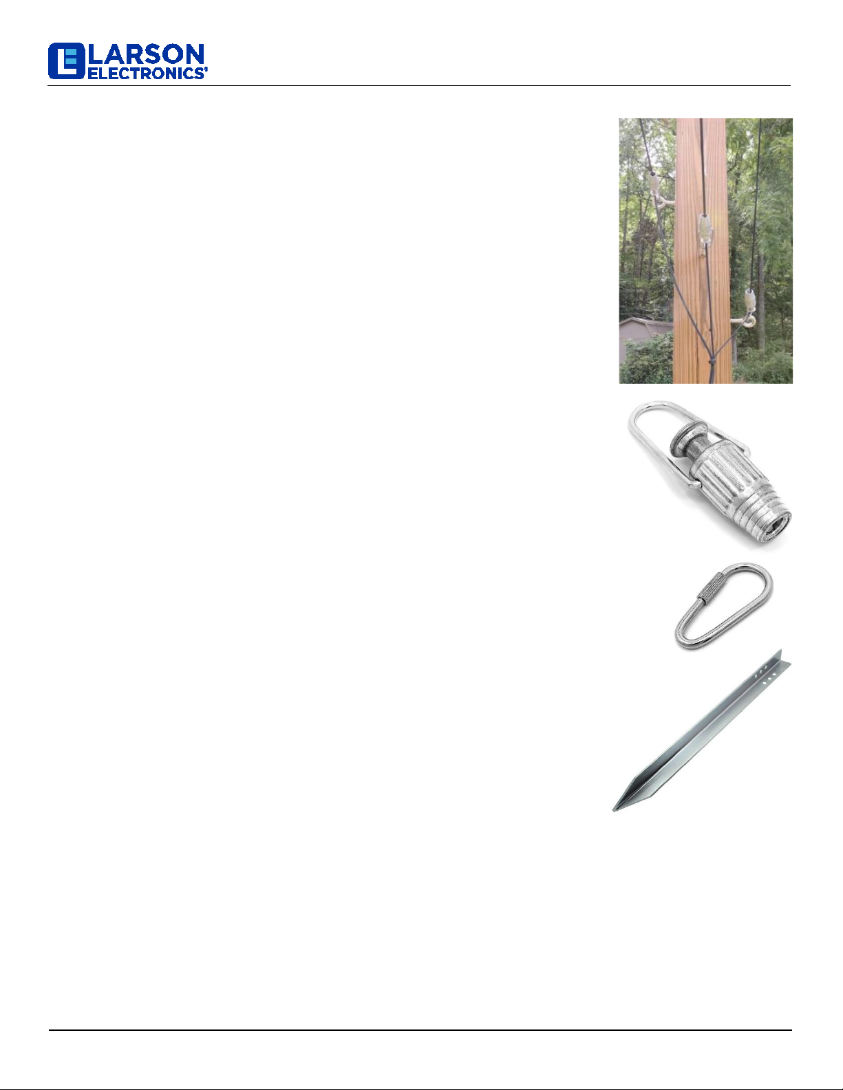
Guying shorter masts depends on your application, and the
item(s) being supported. An adequately spaced, at least 2-
point clamp arrangement on the bottom section may be
sufficient for many light duty or partially-extended
applications. When clamping to fiberglass tubes with U-bolts,
be careful not to over-tighten to avoid crushing the tube.
When in doubt, guy! Err on the side of over-engineering,
never under! Even with guyed structures, always secure the
base in a secure fashion where it cannot move.
In semi-permanent installations, be sure the bottom tube end is not plugged so that water can drain out. Water
can freeze and split the tube if allowed to accumulate. Guy anchor points should be strong enough to
withstand a great deal of pulling force, and away from the mast far enough that the guy ropes form a 45-
degree or greater angle with respect to the mast. If the guy anchor points are too close to the mast, the guys
not only exert a great deal of downward pressure on the mast, adding to the vertical load, but they have far
less mechanical advantage on the structure while doing their job of keeping your mast stable during severe
environmental conditions. Final adjustment of your guy ropes should be without excess slack, but not so tight
as to “load” the mast.
Leverage experienced with tall structures will make them impossible to hold at an angle, so again, keep the
structure vertical at all times during extension and retraction. Having people on all guy ropes to maintain
control (keeping the structure VERTICAL at all times) during raising or lowering the structure is a must.
When letting the structure down, be certain to maintain a firm grip on the inner tubes when you SLOWLY
release tension on the thumb clamp. Do not rely on the clamp tension only to let down each section. Gloves
(selected for a good grip on the tube surface) will be a BIG help. Always raise and lower in adequate lighting to
avoid accidentally extending the mast past the “stop” line you marked on the tubes. Again, ALWAYS have
adequate help on hand to maintain control of the structure when raising or lowering.
MOUNTING
Our Mast line needed a full array of mounting products that could easily be adapted for any use or situation. For permanent
or mobile / temporary use. Not to mention, built to stand the test of time. A trailer hitch mount, ground mount, and drive on
mount, using most of the same components. The same support tube can be paired with one of the plates to make a ground
mount or a drive-on mount, use the holes in the center or the holes toward the end of the plate. Pair the support tube with a
hitch bar and two of our super tough stainless square U-Bolts to make a hitch mount. With a tilt mechanism, you can have
your mast secured in the mounting base and, while the mast is down in the collapsed position, tilt it over and prop your
mast up on something to allow for easy access to the top section of your mast to operate on your antenna, flag, light
fixture, whatever you might have on top. The tilt mechanism is operated by a T-Bolt on the side of the device. You would
remove it to tilt it over. All of our mounting products are made using steel that is laser cut for precise fits and reduced
manufacturing burrs that can scratch the fiberglass masts. The mounts are powder coated for durability and to ensure your
mount has a nice smooth finish. All of the hardware is stainless to make sure that the mount will be as easily operated as
possible for as many years as possible.
NOTE: MOUNTS ARE NOT INCLUDED WITH THIS MAST.
Drive-On Mount Ground Mount Hitch

LMP-FG-50-9.5-TH1-NB-M1
Larson Electronics, LLC Phone: (800) 369-6671 Fax: (903) 498-3364 www.larsonelectronics.com
4of 4
MAINTENANCE
There are no serviceable parts inside the fixture. However, itis good practice to routinely clean and check the
fixture for proper function.
USE AND CARE
Unauthorized modification may impair the function and/or safety of this device and could affect the life of the equipment.
Always check for damaged or worn out parts before using the device. Store it in a secure place out of the reach of children
when not in use.Inspect for good working condition prior to storage and before re-use.
REPLACEMENT PARTS
The LMP-FG-50-9.5-TH1-NB-M1 is designed to provide years of reliable performance. Should the need for replacement
parts arise, please contact Larson Electronics.
THESE INSTRUCTIONS MAY NOT COVER ALL DETAILS OR VARIATIONS OF THIS PRODUCT FOR YOUR EQUIPMENT OR INSTALLATION REQUIREMENTS.
SHOULD FURTHER INFORMATION NOT COVERED BY THESE INSTRUCTIONS BE REQUIRED, PLEASE CONTACT LARSON ELECTRONICS BY EMAIL AT
SA[email protected] OR BY PHONE AT 1-800-369-6671 FOR FURTHER ASSISTANCE.
PLEASE VISIT LARSONELECTRONICS.COM FOR WARRANTY AND RETURN INFORMATION.
Table of contents
Other Larson Electronics Camera Accessories manuals

Larson Electronics
Larson Electronics IND-MD-DF-ESF SP0104 Series User manual

Larson Electronics
Larson Electronics EXP-EXT-3W-SP0104 User manual

Larson Electronics
Larson Electronics BTT-LON-207WH-SMBUS User manual

Larson Electronics
Larson Electronics ALU-TP-158 User manual

Larson Electronics
Larson Electronics AEX-4800 Assembly instructions