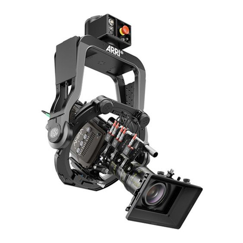
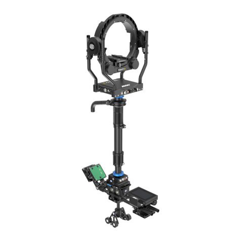
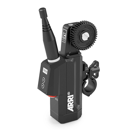
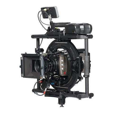
ARRI SRH-360 SUP 3.0 User manual

Stabilized Remote Head
SRH-3 & SRH-360 SUP 3.0
Date 01.06.2021
Manual
Dedicated to these products
KK.0037273
SRH-360 Stabilized Remote Head, No Radio, Set, Standard Joystick
KK.0037275
SRH-360 Stabilized Remote Head, No Radio, Set, Microforce Joystick
KK.0037276
SRH-360 Stabilized Remote Head, No Radio, Set, Broadcast Joystick
Dedicated to these products
KK.0037270
SRH-3 Stabilized Remote Head, No Radio, Set, Standard Joystick
KK.0037271
SRH-3 Stabilized Remote Head, No Radio, Set, Microforce Joystick
KK.0037272
SRH-3 Stabilized Remote Head, No Radio, Set, Broadcast Joystick

2
Imprint
Copyright © 2021 Arnold & Richter Cine Technik GmbH & Co. Betriebs Kg.
All rights reserved.
No parts of this document may be reproduced without prior written consent of Arnold & Richter
Cine Technik GmbH & Co. Betriebs Kg. Specifications are subject to change without NOTE.
Errors, omissions, and modifications excepted.
ARRI, ALEXA, AMIRA, LDS and LENS DATA SYSTEM are trademarks or registered trademarks of
Arnold & Richter Cine Technik GmbH & Co. Betriebs Kg. All other brands or products are
trademarks or registered trademarks of their respective holders and should be treated as such.
Original version.
For further assistance:
Arnold & Richter Cine Technik GmbH & Co. Betriebs Kg
Herbert-Bayer-Str. 10
80807 München
Germany
www.arri.com
Document revision history
Version Release Nr SUP Date
1.1 F07424 3.0 01.06.2021
Scope
This document describes the components and the setup of the SRH-3 and SRH-360
Stabilized Remote Head system and its components.
Disclaimer
Before using the products described in this manual, be sure to read and understand all the respective
instructions.
Otherwise the customer must contact ARRI before using the product.
While ARRI endeavors to enhance the quality, reliability and safety of their products, customers agree
and acknowledge that the possibility of defects thereof cannot be eliminated entirely.
To minimize the risk of damage to property or injury (including death) to persons arising from defects in
the products, customers must incorporate sufficient safety measures in their work with the system and
heed the stated conditions of use.
ARRI or its subsidiaries do not assume any responsibility for losses incurred due to improper handling
or configuration of the product or other system components.
ARRI assumes no responsibility for any errors that may appear in this document.
The information is subject to change without NOTICE.
For product specification changes after this manual was published, refer to the latest published ARRI
data sheets or release notes, etc., for the most up-to-date specifications.
Not all products and/or types are available in every country. Please check with an ARRI sales
representative for availability and additional information.
Neither ARRI nor its subsidiaries assume any liability for infringement of patents, copyrights or other
intellectual property rights of third parties by or arising from the use of ARRI products or any other
liability arising from the use of such products. No license, express, implied or otherwise, is granted
under any patents, copyrights or other intellectual property right of ARRI or others.
ARRI or its subsidiaries expressly exclude any liability, warranty, demand or other obligation for any
claim, representation, cause, action, or whatsoever, express or implied, whether in contract or not,
including negligence, or incorporated in terms and conditions, whether by statue, law or otherwise.
In no event shall ARRI or its subsidiaries be liable for or have a remedy for recovery of any special,
direct, indirect, incidental, or consequential damages, including, but not limited to lost profits, lost
savings, lost revenues or economic loss of any kind or for any claim by a third party, downtime,
good-will, damage to or replacement of equipment or property, any cost or recovery of any material or
goods associated with the assembly or use of our products, or any other damages or injury of the
persons and so on or under any other legal theory.
In the event that one or all of the foregoing clauses are not allowed by applicable law, the fullest extent
permissible clauses by applicable law are validated.

3
Table of Contents
1
User Advisory / Application Requirements ………………………………………………….
4
2
For your safety …………………………………………………………………………………
5
3
Generell Functions / Connectors / Available Cables ………………………………………
7
4
Remote Head Attachment / Mounting, Securing, ISO Damper ….……….………..…….
11
5
Camera Preparation, Mounting and Balancing / Tilt Lock .……..…….…………………..
13
5
Remote Head Setup …………………………………………………………………………..
14
6
Power Supply / Recommended Batteries / Wiring Diagram ………………..……………
15
7
Remote Control Panel / Wiring / Functions ………………………..……………………….
16
8
Remote Control GUI / Functions / Emergency Stop ..……………………………………..
17
9
Controls Setup / Auto Assignment / Manual Assignment / Available Controllers /
Changing Directions / Speed / Ramp ………………………………………………………..
19
10
PID Setup / Quick Setup …………………………………………………..………………….
21
11
Drop ……………………………………………………………………………………………..
23
12
Home Position ………………………………….……………………………………………..
24
13
True Horizon ……………………………………………………………………………………
25
14
True Tilt …………………………………………………………………………………..……..
25
15
End Stops ……………………………………………………………………………………….
26
16
Follow Mode ……………………………………………………………………………………
27
17
Dynamic Modes ………………………………………………………………………………..
28
18
Additional Controls Setup / Dead Band / Sensitivity / Filter / Ratio …………………….
30
19
Additional Remote Head Settings / Pan Motor On/ Off / Motor Mode ………………….
31
20
External Radio Modules / Setup & Range .…………………………………………………
32
21
FIZ Setup Assigning / Available Controllers / Mode / Torque / Calibration / Speed ……..
33
22
Profile Management / Selecting profiles / Cloning Profiles ……………………………….
35
23
Info / Remote Control Panel / Remote Head ………………………………………………..
36
24
Service / Remote Control Panel / Remote Head …………………………………………..
37
25
Power Disconnection …………………………………………………………………………
39
26
Dimensions …………………………………………………………………………………….
39
27
Pinout ……………………………………………………………………………………………
40
28
Assignable Controllers & Functions ..……………………………………………………..
41
29
Declaration of Conformity …………………………………………………………………..
42
Table of Contents

4
1 User Advisory / Application Requirements
The SRH-3 & SRH-360 stabilized remote head and related products should only be used by
experienced and trained operators.
This product is not designed for inexperienced users, and must not be used without proper
training.
Stabilization of remote heads is an extremely complex and at times difficult task and therefore
stabilized remote heads do have their limitations. For example, the remote head will only correct for
angular movement and not parallel movement. This means that when the remote head is attached
directly to a lift, or to a pole, or structure that is subjected to vertical movement, it cannot compensate
for lift as it moves up and down (because that movement is parallel). In order to absorb vertical and
parallel movements, the remote head must be mounted on a suitable shock absorber.
Stabilization systems are limited by engine power, as well as their bandwidth or frequency response.
Very fast movements required to correct the camera position may not be within system capabilities.
This can be seen when using longer lenses.
The use of suitable Iso Dampers devices improves the application.
Mounting a suitable Iso Dampers device between the remote head and the mounting point of the head,
will soak up the fast, unwanted movements, leaving the stabilization with unwanted movements that
are slower and within the bandwidth of the system.
There are many Iso Damper devices that follow different designs and qualities.
Choosing the right Iso Damper is as important as the stabilized head itself.
Another purpose of Iso Dampers is that they decouple the stabilized remote head from some
resonance and flexing of the mounting point.
All gimbal-based stabilized remote heads will always face some kind of drift.
Drift is unwanted movement of the system usually caused by the gyros and the earth’s rotation, which
can’t be measured by the MEMS sensors.
Drift is normally measured in degrees per hour.
The SRH-3 & SRH-360 remote head has a very small amount of drift that would only be noticed while
the head is stationary over a long period of time. The average drift can be up to approximately 10° in
30 minutes. Drift can also be caused by a non-calibrated joystick or a loose camera setup, or an Iso
Damper that is too soft.
Reduction of flexing or bending of the camera and lens package, and flexing of the remote head
attachment are critical. The overall setup needs be as rigid as possible because any flexing can cause
the head to vibrate or oscillate. Every attempt to improve the stiffness of the camera setup and the
head attachment, and to reduce or eliminate any flexing should be made.
Many different camera and lens packages can be used with the SRH-3 & SRH-360, and there are also
many different ways to mount the remote head. As a result, it is not always possible or practical to
obtain perfect conditions regarding rigidity and balance. This may cause the load to become unstable
and it will then shake and oscillate when the stabilization is active. In these situations, adjustment of
the PID parameters will be required. The correct setting of these PID values is crucial for the proper
working of the system.
An unbalanced camera setup will place more strain on the motors of the SRH-3 & SRH-360.
The system will need more force to move the load and this will sometimes increase the possibility of
the load becoming unstable, and that the remote head may over compensate or shake and oscillate.
Please remember that what the remote head is mounted on, and the manner in which it is mounted,
will directly impact on its performance. The total mass of the head and its load are an important
consideration when choosing how and where to mount it. This torque will change in direction and
amplitude in varying amounts. The more solid the mount, the easier it is for the system to perform well.
Sometimes even the leveling linkage on a camera crane will have play or backlash that allows the
mounting point to move slightly when loads are reversed. If there is mechanical play between the
components in the shock absorber, vibrations of the overall system may occur. Iso Dampers with the
appropriate dimensions and hardness should always be used - the system may become too elastic if
the Iso Damper used is too soft, causing vibration.
NOTE
Each of these aspects can lead to the motor power of single axis having to be lowered, which will limit
the effectiveness of the overall stabilization.
User Advisory

5
2 For your safety
How To Use This Manual
All directions are given from a camera operator's point of view.
For example, camera-right side refers to the right side of the camera when standing
behind the camera and operating it in a normal fashion.
Strengthen Your Knowledge and Get Trained
The ARRI Academy courses provide unrivaled insights into the full possibilities of working
with ARRI camera systems, camera stabilizer systems, lenses, lights and accessories.
To learn more, please visit http://arri.com/academy.
2.1
Risk Levels and Alert Symbols
Safety warnings, safety alert symbols, and signal words in these instructions indicate
different risk levels.
The SRH-3 and SRH-360 stabilized remote heads and related products should only
be used by experienced and trained operators. This product is not designed for
inexperienced users and should not and must not be used without proper training.
ARRI recommends that all users of the stabilized remote head read the manual in
its entirety prior to use.
Warning
NOTICE
The product is solely and exclusively available for commercial customers and shall be
used by skilled personnel only. Every user should be trained according to ARRI
guidelines. Use the product only for the purpose described in this document. Always
follow the valid instructions and system requirements for all equipment involved.
DANGER indicates an imminent hazardous situation which,
if not avoided, will result in death or serious injury.
WARNING indicates a potentially hazardous situation which, if not avoided,
may result in death or serious injury.
CAUTION indicates a potentially hazardous situation which, if not avoided,
may result in minor or moderate injury.
NOTICE
NOTE explains practices not related to physical injury. No safety alert
symbol appears with this signal word.
NOTE
Provides additional information to clarify or simplify a procedure.
Warning
CAUTION
DANGER
For your safety
This manual suits for next models
7
Table of contents
Other ARRI Camera Accessories manuals
Popular Camera Accessories manuals by other brands

Trojan
Trojan GC2 48V quick start guide

Calumet
Calumet 7100 Series CK7114 operating instructions

Ropox
Ropox 4Single Series User manual and installation instructions

Cambo
Cambo Wide DS Digital Series Main operating instructions

Samsung
Samsung SHG-120 Specification sheet

Ryobi
Ryobi BPL-1820 Owner's operating manual