3
Larson Electronics LLC - 1.800.369.6671 - sales@larsonelectronics.com - larsonelectronics.com
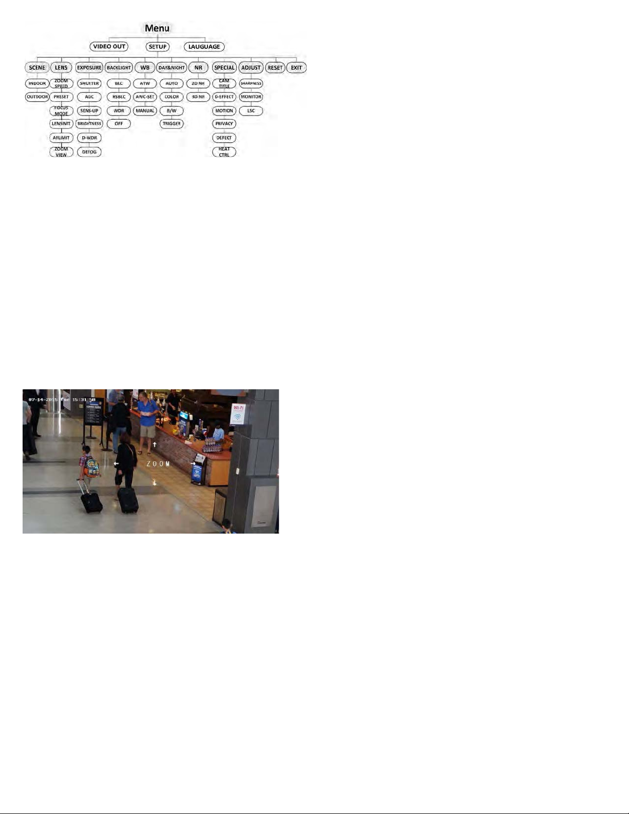
OSD menu tree
MENU: Rock the joystick down or up to select either VIDEO-OUT, SETUP or
LANGUAGE.
VIDEO-OUT: Rock the joystick right or left to select either NTSC or PAL.
LANGUAGE: Rock the joystick right or left to select either English or Chinese
SETUP menu:
•SCENE: Rock the joystick right or left to select either INDOOR or OUTDOOR for
the best image.
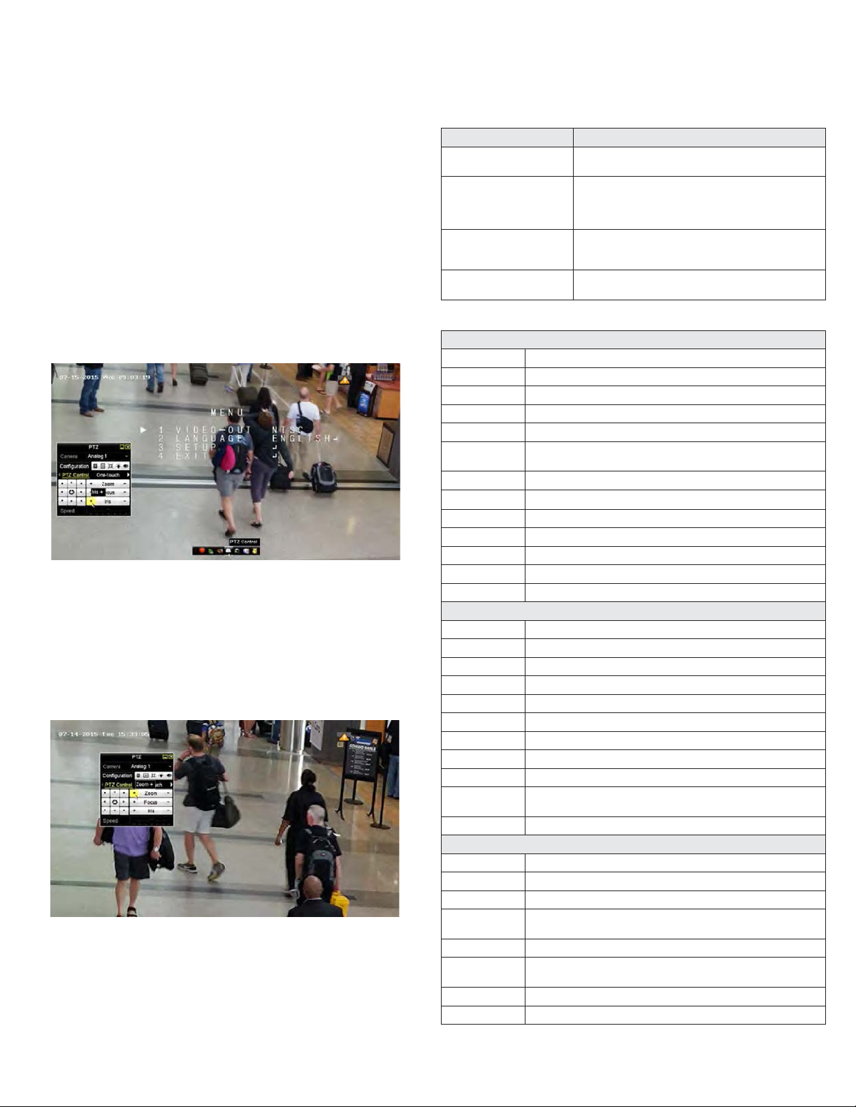
•LENS: The camera is equipped with 5-50 mm motorized vari-focal lens. Click Zoom
+ and Zoom - on the DVR PTZ control to zoom in / out. The camera automatically
focuses after zoom.
—ZOOM SPEED: Move the cursor left/right to adjust the zoom speed.
—PRESET: You can set, delete, and call the preset. You can create up to 64
presets.
SELECT: Select a zoom preset number (1 .. 64).
SET: Press the joystick in open the ZOOM setup tool, and then rock the joystick
up
(p)
or down
(q)
to increase or decrease the zoom. Press the joystick in to save the setting.
DELETE: Clear the zoom preset.
USE: Apply the preset.
—FOCUS MODE: Select either MANUAL, AUTO or TRIGGER. In AUTO mode,
the camera focuses automatically, and in MANUAL mode, click Zoom+ and
Zoom- on the DVR PTZ menu to focus.
—LENSINIT: You can reset the lens.
—AFLIMIT: 20 m, 10 m, 6 m, 3 m, 1.5 m, 1 m, 30 cm, and 10 cm are selectable
as the Min. focus distance limit.
—ZOOM VIEW: Enable the zoom view.
•EXPOSURE
—EXPOSURE: Rock the joystick right or left to select either IRIS-PRIority or
MANUAL. In IRIS-PRI, SHUTTER, AGC sand SENS-UP are not configurable.
—SHUTTER: (EXPOSURE - MANUAL mode only) Rock the joystick right or left to
select either AUTO,
1/25, 1/75, 1/100, 1/120…1/3.5k, 1/6k, 1/10k, 1/20k or 1/30.
—AGC: Rock the joystick right or left to select an AGC value from 0 to 15.
—SENS-UP: Rock the joystick right or left to set the SENS-UP to OFF or AUTO.
—BRIGHTNESS: Rock the joystick right or left to select the brightness value (1 ..
14).
—D-WDR: Rock the joystick right or left to set the D-WDR to ON to improve the
image quality or OFF to disable the function.
—DEFOG: Rock the joystick right or left to set the defog function to OFF or ON.
When set to ON,
press the joystick in to open the submenu. You can set the position, size, and the
defog gradation.
•BACKLIGHT compensation. Rock the joystick right or left to select either OFF,
WDR, HSBLC, or BLC.
—WDR (Wide Dynamic Range): Push the joystick in to open the WDR
submenu. In the submenu, rock the joystick left or right to set the WDR ON or
OFF.
HSBLC: Push the joystick in to open the HSBLC submenu.
AREA: Rock the joystick right or left to select the area (AREA1 .. AREA4) you
want to configure. DISPLAY: Rock the joystick right or left to select either
OFF or ON. If ON, press the joystick in to open set the size and position of
the area by rocking the joystick up, down, left or right. LEVEL: Rock the
joystick right or left to set the HSBLC level (0 .. 100).
MODE: Rock the joystick right or left to select either ALL DAY or NIGHT.
BLACKMASK: Rock the joystick right or left to set the status to ON or OFF.
Default: Restore the HSBLC settings to the default.
—BLC: Push the joystick in to open the BLC submenu.
GAIN: Set the gain of BLC as High, Middle, or Low.
AREA: Press the up/down/left/right button to define the BLC position and
size. Select RET or AGAIN to go back the BLC menu or redefine the BLC
area.
Default: Restore the BLC settings to the default.
•WHITE-BAL: Rock the joystick right or left to select either MANUAL,
ATW (auto-tracking white balance), or AWCSET.
—MANUAL: In this mode, you can set the BLUE level and RED level (1 .. 20).
•DAY&NIGHT: NOTE: For best performance, do not change the default DAY&NIGHT
settings.
•NR (Noise Reduction).
—2DNR: Rock the joystick right or left to select either OFF or ON.
—3DNR: Rock the joystick right or left to select either OFF or ON. If set to ON,
press the joystick in to open the submenu:
SMART NR: Rock the joystick right or left to select either OFF or ON. If ON,
press the joystick in to
select the sensitivity.
LEVEL: Rock the joystick right or left to set the level of noise reduction (0 .. 32).
START AGC: Rock the joystick right or left to set the threshold level to enable
AGC (0 .. 32).
END AGC: Rock the joystick right or left to set the threshold level to disable AGC
(0 .. 100)
•SPECIAL
—CAMERA TITLE: Rock the joystick right or left to select either OFF or ON. If
ON, press the joystick in to compose a camera title. Navigate through the
virtual keyboard by rocking the joystick left, right, up or down. Select a letter by
pressing the joystick in. Select RET to exit.
—D-EFFECT: (digital effect). This group contains the following features:
FREEZE: Rock the joystick right or left to set the FREEZE function either OFF or
ON.
MIRROR: Rock the joystick right or left to set the mirror (image flip) effect to
either OFF, MIRROR, V-FLIP (vertical flip), and ROTATE.
DZOOM: Define the zoom area by configuring the position from PAN & TILT.
SMARTDZOOM: A D-ZOOM area (AREA1 or AREA2) can be ON (enabled),
and the position, sensitivity and time are configurable. When motion is
sensed in the D-ZOOM area, the area is expanded to full screen at the D-
ZOOM factor for the time (seconds) for which it is configured. NEG.IMAGE
(negative image): Rock the joystick right or left to select either OFF or ON.
—MOTION: Rock the joystick right or left to select either OFF or ON. If ON, press
the joystick in to
open MOTION submenu.
SELECT: SELECT a motion detection area (AREA1 .. AREA4), then set the
DISPLAY: Rock the joystick right or left to select either OFF or ON. If ON,
press the joystick in to open the DISPLAY submenu. In this submenu, set the
size and position of the area to sense for motion.
SENSITIVITY Rock the joystick right or left to set the sensitivity level (0 .. 60).
MOTION VIEW: Rock the joystick right or left to select either OFF or ON.
DEFAULT: Push the joystick in to return the settings to the factory default values
for this menu.
—PRIVACY: Rock the joystick right or left to select either OFF or ON. If ON,
press the joystick in to select a PRIVACY shape.
SELECT: Rock the joystick right or left to select the privacy shape (AREA 1 ..
AREA8).
DISPLAY: Select either COLOR, MOSAIC, INVERT, or OFF.
COLOR: Rock the joystick left or right to select a number (represents a
color). Select a number (representing a color ) for the area selected. Then,
press the joystick in to position and set the size of the privacy zone.
TRANS: Rock the joystick left or right to select a transparency level.
DEFAULT: Push the joystick in to return your settings to the factory default values
for this menu.
—DEFECT: Use this feature to compensate for camera imager defects. LIVE
DPC, STATIC DPC and Black DPC are configurable.