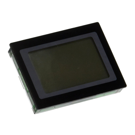
Lascar DPM 342 User manual

DPM 342
LED Backlit 4-20mA Loop
Powered Indicator
Indicateur Alimenté par la
Boucle de Courant 4-20mA
Rétroéclairé à LED
LED-Schleifenstrommesser
mit Beleuchtung, 4-20mA
Indicatore con loop di
alimentazione a 4-20 mA con
retroilluminazione a LED
LASCAR ELECTRONICS, INC.
PO BOX 8204,
SAVANNAH, GA 31412
TEL: +1 (912) 234 2048
FAX: +1 (912) 234 2049
E-MAIL: [email protected]
LASCAR ELECTRONICS LIMITED,
MODULE HOUSE,
WHITEPARISH, SALISBURY,
WILTSHIRE SP5 2SJ UK
TEL: +44 (0)1794 884567
FAX: +44 (0)1794 884616
E-MAIL: [email protected]
www.lascarelectronics.com
8 1
DIMENSIONS
DIMENSIONS
All dimensions in mm (inches)
Toutes les dimensions sont en mm (pouces)
Panel cut-out 38.0 x 18.0 (1.50 x 0.71)
Panel thickness 1.0 to 2.5 (0.04 to 0.1)
Découpe panneau 38,0 x 18,0 (1,50 x 0,71)
1,0 à 2,5 (0,04 to 0,1)Epaisseur panneau
ABMESSUNGEN
DIMENSIONI
Alle Abmessungen in mm (Zoll)
Gehäuseausschnitt
Gehäusestärke
Tutte le dimensioni sono espresse in mm (pollici)
Foratura pannello
Spessore pannello
38,0 x 18,0 (1,50 x 0,71)
1,0 bis 2,5 (0,04 to 0,1)
38,0 x 18,0 (1,50 x 0,71)
1,0 a 2,5 (0,04 to 0,1)
D
D
I
F
GB
GB Specifications liable to change without prior warning DPM 342 Issue 1 November/1999 S.P.W. Applies to DPM 342/1
Spécifications peuvent changer sans préavis DPM 342 Edition 1 novembre/1999 S.P.W. Applique à DPM 342/1
DPM 342 November/1999 S.P.W. DPM 342/1
DPM 342 Novembre/1999 S.P.W. DPM 342/1
Die technischen Daten können ohne vorherige Ankündigung geändert werden Ausgabe 1 Gilt für
Specifiche soggette a variazione senza preavviso Versione 1 Applicabile a
ON BOARD JUMPER LINKS
CAVALIERS EMBARQUES
INTEGRIERTE BRÜCKENVERBINDUNGEN
PONTICELLI DI COLLEGAMENTO INTEGRATI
40.0 (1.57)
27.3 (1.07)
12.7 (0.50)
20.0 (0.79)
17.5 (0.69)
37.5 (1.48)
abc d
a. 2.00 (0.08)
b. 6.00 (0.24)
c. 1.60 (0.06) max
d. 9.50 (0.37)
OFF
DP1
DP2
DP3
LK1
CAL
+-+ -
REAR VIEW
Calibration potentiometers
Potentiomètres de calibrage
Kalibrationspotis
Potenziometri di calibrazione
FI
GB
GB
F
F
D
D
I
I

2 7
A compact loop powered indicator giving an accurate, zero corrected indication of 4-20mA loop
current. Calibration is by two multi-turn potentiometers which allow sensitive adjustment of the
instrument. The DPM 342 features an integral snap-in bezel, making installation easy. The
module’s LED backlighting ensures a clear display, even under low light conditions. No soldering is
required. Connection to the current loop is via two screw terminals. The correct decimal point is
selected via a jumper link.
• 11mm (0.43“) Digit Height • Simple Screw Terminal Connections
• Programmable Decimal Points • Wide Adjustment Range
• Low Volt Drop • Auto-polarity on Display
• Loop Powered LED Backlighting
TERMINAL FUNCTIONS
CALIBRATION
SAFETY
1. + Positive current input.
2. - Negative current input.
The meter is supplied calibrated to read 000 for 4mA loop current and 1000 for 20mA. Calibration is carried out in two
simple stages because the DPM 342 has a very wide adjustment range . Place the jumper link across LK1. This disables the
offset adjustment to enable span adjustment to be made first. After span adjustment is complete, the jumper link is removed
and the offset adjustment is made. The jumper link is then used to display one of the decimal points if necessary.
Example to re-calibrate: Meter to read -40.0 for 4mA and 150.0 for 20mA.
1. Calculate the span by subtracting the desired reading at 4mA from the desired reading at 20mA: -1500 - (-400) = 1900
2. Short jumper link Lk1 with the link header normally used to select the desired Decimal Point.
Link Lk1 is located above the screw terminals.
3. Apply 16mA between the + and - screw terminals.
4. Adjust the CAL potentiometer so the DPM 342 indicates 1900.
5. Remove jumper link Lk1 and place it back on the desired Decimal Point (DP1 in this case).
6. Apply 4mA between the - and + screw terminals.
7. Adjust the OFF potentiometer so the DPM 342 indicates the desired reading at 4mA: -40.0
8. Adjust CAL and OFF as necessary for optimum accuracy, by repeating steps 2 to 7.
The user must ensure that the incorporation of the DPM into the user’s equipment conforms to the relevant sections of BS EN
61010 (Safety Requirements for Electrical Equipment for Measuring, Control and Laboratory Use). No inputs other than 4-
20mA indicating loop current should be made.
Locate the meter by passing it through the front of the panel cut-out and gently push until the rear of the bezel is flush with the
panel (DO NOT PUSH ON THE LCD). The snap-in lugs will now automatically hold the meter firmly in position. Take care
when inserting the meter, not to damage the current loop wires and not to short them on the panel.
PANEL FITTING
JUMPER LINKS
In order to quickly and easily select the required Decimal Point, the meter has several on-board jumper links.
CAVALIERS
BRÜCKENVERBINDUNGEN
PONTICELLI DI COLLEGAMENTO
Pour pouvoir sélectionner rapidement et facilement le Point Décimal approprié, le mètre est équipé de plusieurs
cavaliers embarqués.
Um die gewünschte Dezimalpunktkonfiguration schnell und problemlos auswählen zu können, sind am Gerät mehrere
integrale Brückenverbindungen vorgesehen.
Per selezionare in modo semplice e rapido il punto decimale richiesto, il misuratore dispone di vari ponticelli di
collegamento integrati.
DP1
DP3
DP2
DP1
DP3
DP2
DP1
DP3
DP2
I+ +
I- -
Connecting the DPM 342 to a 4-20mA Current Loop.
Connexion du DPM 342 à une Boucle de Courant 4-20mA.
Anschluß des DPM 342 an einen4-20mASchleifenstrom.
Connessione dell'apparecchio DPM 342 al loop di corrente a 4-20 mA.
CURRENT LOOP CONNECTION
The DPM 342 and its backlighting are powered from the 4-20mA signal loop and need no other power supply. Ensure
correct polarity when connecting.
CONNEXION A LA BOUCLE DE COURANT
Le DPM 342 et son rétroéclairage sont alimentés à partir de la boucle de signal 4-20mA et n'ont besoin d'aucune autre
alimentation. Veillez à bien respecter la polarité lors de la connexion.
Der DPM 342 sowie die Hintergrundbeleuchtung werden vom4-20mASignalschleifenstrom versorgt, weshalb sich
jede weitere Stromversorgung erübrigt. Stellen Sie beim Anschluß die korrekte Polarität sicher.
L'apparecchio DPM 342 e il relativo sistema di retroilluminazione vengono alimentati dal loop di segnale a 4-20 mA e
quindi non necessitano di altre fonti di alimentazione. Al momento della connessione, assicurarsi che la polarità sia
corretta.
SCHLEIFENSTROMANSCHLUSS
CONNESSIONE AL LOOP DI CORRENTE
Transmetteur
4-20mA
4-20mA
Transmitter
DPM 342
4-20mA Sender
Trasmettitore
a 4-20 mA
GB
GB
GB
F
F
F
D
D
D
I
I
I

6 3
Indicateur compact, alimenté par la boucle de courant et donnant une indication précise corrigée
de zéro du courant de boucle 4-20mA. Le calibrage s'effectue au moyen de deux potentiomètres
multitours permettant un réglage précis de l'appareil. L'installation du DPM 342 est également
facilitée grâce à un cadre intégrale encliquetable. Le rétroéclairage à LED du module assure un
affichage clair, et ce, même en cas de faible luminosité. Aucun brasage n'est nécessaire. La
connexion à la boucle de courant s'effectue via deux bornes à vis. La sélection du point décimal
approprié s'effectue via un cavalier.
Taille des Caractères 11mm (0,43") Connexions Simples par Bornes à Vis
Points Décimaux Programmables Large Plage de Réglage
Faible Chute de Tension Polarité automatique sur l'Ecran
Rétroéclairage à LED Alimenté par
la Boucle de Courant
••
••
••
•
FONCTIONS DES BROCHES
SECURITE
1. + Entrée en courant positif.
2. - Entrée en courant négatif.
Le mètre à l'origine est calibré pour lire 000 pour une boucle de courant 4mA et 1000 pour 20mA. Le calibrage s'effectue
simplement en deux étapes étant donné que le DPM 342 dispose d'une très large plage de réglage. Placez le cavalier sur LK1.
Cela permet d'invalider le réglage du décalage et de régler d'abord la portée. Lorsque le réglage de la portée est terminé, retirez
le cavalier et procédez au réglage du décalage. Le cavalier peut alors être utilisé pour afficher un des points décimaux, si
nécessaire.
Exemple de recalibrage: pour une lecture du mètre de -40,0 pour 4mA et de 150,0 pour 20mA.
1. Calculez la portée en soustrayant la lecture souhaitée à 4mA de la lecture souhaitée à 20mA: -1500 (-400) = 1900
2. Court-circuitez le cavalier Lk1 avec l'embase de liaison utilisée normalement pour sélectionner le Point Décimal désiré.
La liaison Lk1 se trouve au-dessus des bornes à vis.
3. Appliquez 16mA entre les bornes à vis + et -.
4. Réglez le potentiomètre CAL pour que le DPM 342 indique 1900.
5. Retirez le cavalier Lk1 et replacez-le sur le Point Décimal désiré (DP1 dans ce cas).
6. Appliquez 4mA entre les bornes à vis + et -.
7. Réglez le potentiomètre OFF de façon à ce que le DPM 342 indique la lecture désirée à 4mA: -40,0
8. Réglez au besoin CAL et OFF pour une précision optimale en répétant les étapes2à7.
L'utilisateur doit s'assurer que l'intégration du DPM dans son équipement est conforme aux sections pertinentes du BS EN 61010
(Exigences de Sécurité pour le Matériel Electrique de Mesure, de Contrôle et de Laboratoire). Aucune autre entrée qu'un
courant de boucle indiquant 4-20mA ne doit être effectuée.
Positionnez le mètre dans la découpe du panneau et appuyez délicatement jusqu'à ce que l'arrière du cadre soit au ras du
panneau (N'APPUYEZ PAS SUR L'AFFICHEUR A CRISTAUX LIQUIDES). Les ergots encliquetables maintiennent ensuite
automatiquement le mètre fermement en place. Faites attention lorsque vous insérez le mètre à ne pas endommager les fils de la
boucle de courant et à ne pas les court-circuiter sur le panneau.
CALIBRAGE
ENCASTREMENT
Specification Min. Typ. Max. Unit
Accuracy (overall error) * 0.05 0.1 %(±1 count)
Linearity ±1 count
Sample rate 3 samples/sec
Operating temperature range 0 50 °C
Temperature stability 200 ppm/°C
Loop volt drop 5 5.6 6 V
Supply current 4 mA
Full scale reading (20mA) 0 1999 Count
Offset adjustment range -1200 +1200 Count
* To ensure maximum accuracy, re-calibrate periodically.
Caractéristiques Min. Typ. Max. Unité
Précision (erreur globale) * 0,05 0,1 %(±1 compte)
Linéarité ±1 compte
Taux d'échantillonnage 3 éch./sec
Températures limites d'utilisation 0 50 °C
Stabilité thermique 200 ppm/°C
Chute de tension de la boucle 5 5,6 6 V
Courant d'alimentation 4 mA
Lecture pleine échelle (20mA) 0 1999 Compte
Adjustement d'offset -1200 +1200 Compte
* Pour obtenir une précision maximum, recalibrez périodiquement.
Spezifikation Min. Typ. Max. Einheit
* 0,05 0,1
±1
3
050°C
200 ppm/°C
5 5,6 6 V
4mA
0 1999
-1200 +1200
*
Genauigkeit (Gesamtfehler) %(± 1 Zahl)
Linearität Zahl
Meßrate Messungen/s
Betriebstemperaturbereich
Temperaturstabilität
Schleifenspannungsabfall
Versorgungsstrom
Meßbereichsendwert (20 mA) Zahl
Offset-Einstellbereich Zahl
Um die maximale Genauigkeit sicherzustellen, regelmäßig nachkalibrieren.
Specifiche Min. Typ. Max. U.M.
* 0,05 0,1
±1
3
050°C
200 ppm/°C
5 5,6 6 V
4mA
0 1999
-1200 +1200
*
Precisione (errore complessivo) % (± 1 conteggio)
Linearità conteggi
Frequenza di campionamento campioni/sec.
Campo della temperatura di esercizio
Stabilità termica
Caduta di tensione del loop
Corrente di alimentazione
Lettura di fondo scala (20 mA) conteggi
Portata di regolazione dello sbilanciamento conteggi
Per garantire la massima precisione, ripetere periodicamente la calibrazione.
Method Screw terminals -
No Connector Reqiured
Methode Bornier à Vis -
Connecteur pas nécessaire
Methode Schraubklemmen Keine
weiteren Anschlüsse
erforderlich.
Metodo Terminali a vite Non
sono richiesti connettori
CONNECTOR SOURCE GUIDE
REFERENCE DES CONNECTEURS
ANSCHLUSSRICHTLINIE
GUIDA ALLE FONTI DI
PROVENIENZA DEI
CONNETTORI
GBFDI

4 5
Ein kompakter Schleifenstrommesser für akkurate, nullkorrigierte Stromanzeige im Bereich4-20
mA. Die Kalibration erfolgt über zwei Mehrstellungspotis, die eine empfindliche Einstellung des
Instruments ermöglichen. Der DPM 342 weist für den einfachen Einbau einen integrierten
Einrastrahmen auf. Die LED-Hintergrundbeleuchtung des Moduls vermittelt klare Lesbarkeit,
auch bei schwacher Umgebungsbeleuchtung. Jedes Löten erübrigt sich. Der Anschluß an die
Stromschleife erfolgt über zwei Schraubklemmen. Der korrekte Dezimalpunkt wird über eine
Brückenverbindung ausgewählt.
• 11mm (0,43") Zahlhöhe • Einfache Schraubklemmen
• Programmierbarer Dezimalpunkt • Weiter Einstellbereich
• Geringer Spannungsabfall • Automatische Anzeigenpolarität
• Schleifenstrom-LED mit Hintergrundbeleuchtung
KLEMMENFUNKTION
KALIBRATION
SICHERHEIT
GEHÄUSEMONTAGE
1. + Plusstromeingang
2. - Minusstromeingang
Das Instrument mißt im Anlieferungszustand 000 bei 4 mA Schleifenstrom und 1000 bei 20 mA. Die Kalibration erfolgt wegen
des weiten Einstellbereichs in zwei einfachen Schritten. Legen Sie als erstes die Brückenverbindung über LK1. Dadurch wird die
Offset-Einstellung ausgeschaltet, um zunächst eine Einstellung des Ausschlagbereichs vornehmen zu können. Nach
abgeschlossener Einstellung des Ausschlagbereichs müssen Sie die Verbindung wieder entfernen und die Offset-Einstellung
durchführen. Dann wird die Brückenverbindung, nach Bedarf, zum Darstellen einer der möglichen Dezimalpunkteinstellungen
benutzt.
Beispiel einer Nachkalibration: Das Instrument soll bei 4 mA 40,0 und 150,0 bei 20 mA anzeigen.
1. Berechnen Sie den Einstellbereich durch Abziehen der gewünschten Anzeige bei 4 mA von der gewünschten Anzeige bei
20 mA: -1500 (-400) = 1900
2. Schließen Sie die Brückenverbindung LK1 kurz, deren Verbindungskopf normalerweise zur Auswahl der gewünschten
Dezimalpunktoption verwendet wird. Diese Verbindung befindet sich über den Schraubklemmen.
3. Setzen Sie 16 mA zwischen den Plus- und Minusklemmen an.
4. Stellen Sie den CAL-Poti so ein, daß der DPM 342 1900 anzeigt.
5. Entfernen Sie die Brückenverbindung LK1 und setzen diese wieder auf die gewünschte Dezimalpunktoption (in diesem Fall
DP1) ein.
6. Setzen Sie 4 mA zwischen den Minus- und Plusklemmen an.
7. Stellen Sie den OFF-Poti so ein, daß der DPM 342 bei 4 mA den gewünschten Wert anzeigt: -40.0
8. Stellen Sie die CAL- und OFF-Potis nach Bedarf für maximale Genauigkeit ein, indem Sie die Schritte 2 bis 7 bei Bedarf
wiederholen.
Stellen Sie sicher, daß die Aufnahme des DPM in die Benutzeranlagen mit den zutreffenden Abschnitten von BS EN 6101
(Sicherheitsvorschriften für Elektrogeräte zum Messen, Regeln und im Labor) übereinstimmt. Eingänge anders als4-20mAam
Schleifenstrommesser dürfen nicht vorgenommen werden.
Lokalisieren Sie das Instrument von der Vorderseite durch einen Gehäuseausschnitt und schieben es vorsichtig herein, bis die
Rückseite des Rahmens mit der Gehäusewand bündig ist (DRÜCKEN SIE NIE AUF DIE LCD). Die Einrastvorsprünge halten das
Instrument dann sicher in seiner Einbaulage. Achten Sie beim Einführen des Instruments darauf, daß die Schleifenstromdrähte
weder beschädigt noch am Gehäuse kurzgeschlossen werden.
Indicatore con loop di alimentazione compatto che fornisce un'indicazione precisa e corretta sullo
zero della corrente del loop a 4-20 mA. La calibrazione viene eseguita mediante due
potenziometri multigiri, che consentono di regolare lo strumento con estrema precisione. Il DPM
342 è dotato di una cornice a scatto integrata, che ne agevola l'installazione. La retroilluminazione
a LED del modulo assicura una buona visualizzazione anche in condizioni di luce carente. Non
sono richiesti lavori di saldatura. La connessione al loop di corrente viene effettuata mediante due
terminali a vite. Il punto decimale corretto viene selezionato tramite un ponticello di
collegamento.
• Altezza dei digit di 11 mm (0.43") • Semplici connessioni con terminali a vite
• Punti decimali programmabili • Ampia portata di regolazione
• Caduta di tensione del loop • Regolazione automatica di polarità su display
• Retroilluminazione a LED con loop di alimentazione
FUNZIONI DEI TERMINALI
CALIBRAZIONE
SICUREZZA
MONTAGGIO A PANNELLO
1. Ingresso di corrente pos. (+).
2. Ingresso di corrente neg. (-).
Il misuratore viene fornito calibrato a 000 per un loop di corrente a 4 mA e a 1000 per 20 mA. La calibrazione viene eseguita in
due semplici fasi, in quanto l'apparecchio DPM 342 dispone di una portata di regolazione particolarmente ampia. Posizionare il
ponticello di collegamento su Lk1. Questa operazione disabilita la regolazione dello sbilanciamento per consentire di eseguire
innanzitutto la regolazione dell'intervallo. Dopo avere terminato la regolazione dell'intervallo, si procederà alla rimozione del
ponticello di collegamento e quindi alla regolazione dello sbilanciamento. Il ponticello di collegamento viene poi utilizzato, se
necessario, per visualizzare uno dei punti decimali.
Esempio di ricalibrazione: valori di lettura 40.0 per 4 mA e 150.0 per 20 mA.
1. Calcolare l'intervallo sottraendo la lettura desiderataa4mAdalla lettura desiderata a 20 mA: -1500 (-400) = 1900.
2. Cortocircuitare il ponticello di collegamento Lk1 con la basetta di supporto solitamente utilizzata per selezionare il punto
decimale desiderato. Il collegamento Lk1 è situato sopra i terminali a vite.
3. Applicare 16 mA tra i terminali a vite+e-.
4. Regolare il potenziometro CAL in modo tale che l'apparecchio DPM 342 indichi il valore 1900.
5. Rimuovere il ponticello di collegamento Lk1 e riposizionarlo sul punto decimale desiderato (in questo caso DP1).
6. Applicare 4 mA tra i terminali a vite e +.
7. Regolare il potenziometro OFF in modo tale che l'apparecchio DPM 342 indichi la lettura desiderata a 4 mA, ossia 40.0.
8. Regolare CAL e OFF sino ad ottenere un grado di precisione ottimale, ripetendo le fasi da2a7.
L'operatore deve assicurarsi che l'integrazione dell'apparecchio DPM nella propria attrezzatura sia conforme alle relative sezioni
della normativa BS EN 61010 (Requisiti di sicurezza delle attrezzature elettriche per la misurazione, il controllo e gli impieghi di
laboratorio). Non utilizzare una corrente di loop in ingresso con valori diversi da 4-20 mA.
Posizionare il misuratore inserendolo nella parte anteriore della foratura del pannello ed esercitare una leggera pressione sino a
quando la parte posteriore della cornice risulterà a livello del pannello (NON PREMERE SUL DISPLAY LCD). Le linguette a scatto
consentono di mantenere saldamente in posizione il misuratore. Durante l'inserimento dell'apparecchio, prestare attenzione a
non danneggiare i fili del loop di corrente e a non cortocircuitarli sul pannello.

6 3
Indicateur compact, alimenté par la boucle de courant et donnant une indication précise corrigée
de zéro du courant de boucle 4-20mA. Le calibrage s'effectue au moyen de deux potentiomètres
multitours permettant un réglage précis de l'appareil. L'installation du DPM 342 est également
facilitée grâce à un cadre intégrale encliquetable. Le rétroéclairage à LED du module assure un
affichage clair, et ce, même en cas de faible luminosité. Aucun brasage n'est nécessaire. La
connexion à la boucle de courant s'effectue via deux bornes à vis. La sélection du point décimal
approprié s'effectue via un cavalier.
Taille des Caractères 11mm (0,43") Connexions Simples par Bornes à Vis
Points Décimaux Programmables Large Plage de Réglage
Faible Chute de Tension Polarité automatique sur l'Ecran
Rétroéclairage à LED Alimenté par
la Boucle de Courant
••
••
••
•
FONCTIONS DES BROCHES
SECURITE
1. + Entrée en courant positif.
2. - Entrée en courant négatif.
Le mètre à l'origine est calibré pour lire 000 pour une boucle de courant 4mA et 1000 pour 20mA. Le calibrage s'effectue
simplement en deux étapes étant donné que le DPM 342 dispose d'une très large plage de réglage. Placez le cavalier sur LK1.
Cela permet d'invalider le réglage du décalage et de régler d'abord la portée. Lorsque le réglage de la portée est terminé, retirez
le cavalier et procédez au réglage du décalage. Le cavalier peut alors être utilisé pour afficher un des points décimaux, si
nécessaire.
Exemple de recalibrage: pour une lecture du mètre de -40,0 pour 4mA et de 150,0 pour 20mA.
1. Calculez la portée en soustrayant la lecture souhaitée à 4mA de la lecture souhaitée à 20mA: -1500 (-400) = 1900
2. Court-circuitez le cavalier Lk1 avec l'embase de liaison utilisée normalement pour sélectionner le Point Décimal désiré.
La liaison Lk1 se trouve au-dessus des bornes à vis.
3. Appliquez 16mA entre les bornes à vis + et -.
4. Réglez le potentiomètre CAL pour que le DPM 342 indique 1900.
5. Retirez le cavalier Lk1 et replacez-le sur le Point Décimal désiré (DP1 dans ce cas).
6. Appliquez 4mA entre les bornes à vis + et -.
7. Réglez le potentiomètre OFF de façon à ce que le DPM 342 indique la lecture désirée à 4mA: -40,0
8. Réglez au besoin CAL et OFF pour une précision optimale en répétant les étapes2à7.
L'utilisateur doit s'assurer que l'intégration du DPM dans son équipement est conforme aux sections pertinentes du BS EN 61010
(Exigences de Sécurité pour le Matériel Electrique de Mesure, de Contrôle et de Laboratoire). Aucune autre entrée qu'un
courant de boucle indiquant 4-20mA ne doit être effectuée.
Positionnez le mètre dans la découpe du panneau et appuyez délicatement jusqu'à ce que l'arrière du cadre soit au ras du
panneau (N'APPUYEZ PAS SUR L'AFFICHEUR A CRISTAUX LIQUIDES). Les ergots encliquetables maintiennent ensuite
automatiquement le mètre fermement en place. Faites attention lorsque vous insérez le mètre à ne pas endommager les fils de la
boucle de courant et à ne pas les court-circuiter sur le panneau.
CALIBRAGE
ENCASTREMENT
Specification Min. Typ. Max. Unit
Accuracy (overall error) * 0.05 0.1 %(±1 count)
Linearity ±1 count
Sample rate 3 samples/sec
Operating temperature range 0 50 °C
Temperature stability 200 ppm/°C
Loop volt drop 5 5.6 6 V
Supply current 4 mA
Full scale reading (20mA) 0 1999 Count
Offset adjustment range -1200 +1200 Count
* To ensure maximum accuracy, re-calibrate periodically.
Caractéristiques Min. Typ. Max. Unité
Précision (erreur globale) * 0,05 0,1 %(±1 compte)
Linéarité ±1 compte
Taux d'échantillonnage 3 éch./sec
Températures limites d'utilisation 0 50 °C
Stabilité thermique 200 ppm/°C
Chute de tension de la boucle 5 5,6 6 V
Courant d'alimentation 4 mA
Lecture pleine échelle (20mA) 0 1999 Compte
Adjustement d'offset -1200 +1200 Compte
* Pour obtenir une précision maximum, recalibrez périodiquement.
Spezifikation Min. Typ. Max. Einheit
* 0,05 0,1
±1
3
050°C
200 ppm/°C
5 5,6 6 V
4mA
0 1999
-1200 +1200
*
Genauigkeit (Gesamtfehler) %(± 1 Zahl)
Linearität Zahl
Meßrate Messungen/s
Betriebstemperaturbereich
Temperaturstabilität
Schleifenspannungsabfall
Versorgungsstrom
Meßbereichsendwert (20 mA) Zahl
Offset-Einstellbereich Zahl
Um die maximale Genauigkeit sicherzustellen, regelmäßig nachkalibrieren.
Specifiche Min. Typ. Max. U.M.
* 0,05 0,1
±1
3
050°C
200 ppm/°C
5 5,6 6 V
4mA
0 1999
-1200 +1200
*
Precisione (errore complessivo) % (± 1 conteggio)
Linearità conteggi
Frequenza di campionamento campioni/sec.
Campo della temperatura di esercizio
Stabilità termica
Caduta di tensione del loop
Corrente di alimentazione
Lettura di fondo scala (20 mA) conteggi
Portata di regolazione dello sbilanciamento conteggi
Per garantire la massima precisione, ripetere periodicamente la calibrazione.
Method Screw terminals -
No Connector Reqiured
Methode Bornier à Vis -
Connecteur pas nécessaire
Methode Schraubklemmen Keine
weiteren Anschlüsse
erforderlich.
Metodo Terminali a vite Non
sono richiesti connettori
CONNECTOR SOURCE GUIDE
REFERENCE DES CONNECTEURS
ANSCHLUSSRICHTLINIE
GUIDA ALLE FONTI DI
PROVENIENZA DEI
CONNETTORI
GBFDI

2 7
A compact loop powered indicator giving an accurate, zero corrected indication of 4-20mA loop
current. Calibration is by two multi-turn potentiometers which allow sensitive adjustment of the
instrument. The DPM 342 features an integral snap-in bezel, making installation easy. The
module’s LED backlighting ensures a clear display, even under low light conditions. No soldering is
required. Connection to the current loop is via two screw terminals. The correct decimal point is
selected via a jumper link.
• 11mm (0.43“) Digit Height • Simple Screw Terminal Connections
• Programmable Decimal Points • Wide Adjustment Range
• Low Volt Drop • Auto-polarity on Display
• Loop Powered LED Backlighting
TERMINAL FUNCTIONS
CALIBRATION
SAFETY
1. + Positive current input.
2. - Negative current input.
The meter is supplied calibrated to read 000 for 4mA loop current and 1000 for 20mA. Calibration is carried out in two
simple stages because the DPM 342 has a very wide adjustment range . Place the jumper link across LK1. This disables the
offset adjustment to enable span adjustment to be made first. After span adjustment is complete, the jumper link is removed
and the offset adjustment is made. The jumper link is then used to display one of the decimal points if necessary.
Example to re-calibrate: Meter to read -40.0 for 4mA and 150.0 for 20mA.
1. Calculate the span by subtracting the desired reading at 4mA from the desired reading at 20mA: -1500 - (-400) = 1900
2. Short jumper link Lk1 with the link header normally used to select the desired Decimal Point.
Link Lk1 is located above the screw terminals.
3. Apply 16mA between the + and - screw terminals.
4. Adjust the CAL potentiometer so the DPM 342 indicates 1900.
5. Remove jumper link Lk1 and place it back on the desired Decimal Point (DP1 in this case).
6. Apply 4mA between the - and + screw terminals.
7. Adjust the OFF potentiometer so the DPM 342 indicates the desired reading at 4mA: -40.0
8. Adjust CAL and OFF as necessary for optimum accuracy, by repeating steps 2 to 7.
The user must ensure that the incorporation of the DPM into the user’s equipment conforms to the relevant sections of BS EN
61010 (Safety Requirements for Electrical Equipment for Measuring, Control and Laboratory Use). No inputs other than 4-
20mA indicating loop current should be made.
Locate the meter by passing it through the front of the panel cut-out and gently push until the rear of the bezel is flush with the
panel (DO NOT PUSH ON THE LCD). The snap-in lugs will now automatically hold the meter firmly in position. Take care
when inserting the meter, not to damage the current loop wires and not to short them on the panel.
PANEL FITTING
JUMPER LINKS
In order to quickly and easily select the required Decimal Point, the meter has several on-board jumper links.
CAVALIERS
BRÜCKENVERBINDUNGEN
PONTICELLI DI COLLEGAMENTO
Pour pouvoir sélectionner rapidement et facilement le Point Décimal approprié, le mètre est équipé de plusieurs
cavaliers embarqués.
Um die gewünschte Dezimalpunktkonfiguration schnell und problemlos auswählen zu können, sind am Gerät mehrere
integrale Brückenverbindungen vorgesehen.
Per selezionare in modo semplice e rapido il punto decimale richiesto, il misuratore dispone di vari ponticelli di
collegamento integrati.
DP1
DP3
DP2
DP1
DP3
DP2
DP1
DP3
DP2
I+ +
I- -
Connecting the DPM 342 to a 4-20mA Current Loop.
Connexion du DPM 342 à une Boucle de Courant 4-20mA.
Anschluß des DPM 342 an einen4-20mASchleifenstrom.
Connessione dell'apparecchio DPM 342 al loop di corrente a 4-20 mA.
CURRENT LOOP CONNECTION
The DPM 342 and its backlighting are powered from the 4-20mA signal loop and need no other power supply. Ensure
correct polarity when connecting.
CONNEXION A LA BOUCLE DE COURANT
Le DPM 342 et son rétroéclairage sont alimentés à partir de la boucle de signal 4-20mA et n'ont besoin d'aucune autre
alimentation. Veillez à bien respecter la polarité lors de la connexion.
Der DPM 342 sowie die Hintergrundbeleuchtung werden vom4-20mASignalschleifenstrom versorgt, weshalb sich
jede weitere Stromversorgung erübrigt. Stellen Sie beim Anschluß die korrekte Polarität sicher.
L'apparecchio DPM 342 e il relativo sistema di retroilluminazione vengono alimentati dal loop di segnale a 4-20 mA e
quindi non necessitano di altre fonti di alimentazione. Al momento della connessione, assicurarsi che la polarità sia
corretta.
SCHLEIFENSTROMANSCHLUSS
CONNESSIONE AL LOOP DI CORRENTE
Transmetteur
4-20mA
4-20mA
Transmitter
DPM 342
4-20mA Sender
Trasmettitore
a 4-20 mA
GB
GB
GB
F
F
F
D
D
D
I
I
I

DPM 342
LED Backlit 4-20mA Loop
Powered Indicator
Indicateur Alimenté par la
Boucle de Courant 4-20mA
Rétroéclairé à LED
LED-Schleifenstrommesser
mit Beleuchtung, 4-20mA
Indicatore con loop di
alimentazione a 4-20 mA con
retroilluminazione a LED
LASCAR ELECTRONICS, INC.
PO BOX 8204,
SAVANNAH, GA 31412
TEL: +1 (912) 234 2048
FAX: +1 (912) 234 2049
LASCAR ELECTRONICS LIMITED,
MODULE HOUSE,
WHITEPARISH, SALISBURY,
WILTSHIRE SP5 2SJ UK
TEL: +44 (0)1794 884567
FAX: +44 (0)1794 884616
www.lascarelectronics.com
8 1
DIMENSIONS
DIMENSIONS
All dimensions in mm (inches)
Toutes les dimensions sont en mm (pouces)
Panel cut-out 38.0 x 18.0 (1.50 x 0.71)
Panel thickness 1.0 to 2.5 (0.04 to 0.1)
Découpe panneau 38,0 x 18,0 (1,50 x 0,71)
1,0 à 2,5 (0,04 to 0,1)Epaisseur panneau
ABMESSUNGEN
DIMENSIONI
Alle Abmessungen in mm (Zoll)
Gehäuseausschnitt
Gehäusestärke
Tutte le dimensioni sono espresse in mm (pollici)
Foratura pannello
Spessore pannello
38,0 x 18,0 (1,50 x 0,71)
1,0 bis 2,5 (0,04 to 0,1)
38,0 x 18,0 (1,50 x 0,71)
1,0 a 2,5 (0,04 to 0,1)
D
D
I
F
GB
GB Specifications liable to change without prior warning DPM 342 Issue 1 November/1999 S.P.W. Applies to DPM 342/1
Spécifications peuvent changer sans préavis DPM 342 Edition 1 novembre/1999 S.P.W. Applique à DPM 342/1
DPM 342 November/1999 S.P.W. DPM 342/1
DPM 342 Novembre/1999 S.P.W. DPM 342/1
Die technischen Daten können ohne vorherige Ankündigung geändert werden Ausgabe 1 Gilt für
Specifiche soggette a variazione senza preavviso Versione 1 Applicabile a
ON BOARD JUMPER LINKS
CAVALIERS EMBARQUES
INTEGRIERTE BRÜCKENVERBINDUNGEN
PONTICELLI DI COLLEGAMENTO INTEGRATI
40.0 (1.57)
27.3 (1.07)
12.7 (0.50)
20.0 (0.79)
17.5 (0.69)
37.5 (1.48)
abc d
a. 2.00 (0.08)
b. 6.00 (0.24)
c. 1.60 (0.06) max
d. 9.50 (0.37)
OFF
DP1
DP2
DP3
LK1
CAL
+-+ -
REAR VIEW
Calibration potentiometers
Potentiomètres de calibrage
Kalibrationspotis
Potenziometri di calibrazione
FI
GB
GB
F
F
D
D
I
I
Table of contents
Other Lascar Measuring Instrument manuals
Popular Measuring Instrument manuals by other brands

Emerson
Emerson 3200 Installation, operation and maintenance instructions

LOVATO ELECTRIC
LOVATO ELECTRIC DME D300T2 MID instruction manual

Siemens
Siemens WFx6 Series Operating and installation instructions

ELAP
ELAP HPS-M-05 instruction manual

Trolex
Trolex XD1+ user manual

TOTAL Lubmarine
TOTAL Lubmarine Tech'Care user guide