2 7
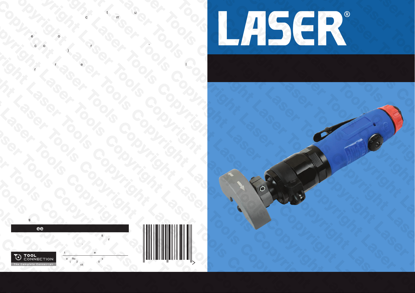
Flexible Head Air Cut Off Tool
With its low weight design, comfort grip and 3-position flexi-head design, this cut off tool
from Laser Tools is the perfect addition to your tool box. Features an easy to use safety
lock off throttle lever, speed control, forward and reverse cutting wheel rotation, adjustable-
position rear exhaust, 0.7 horsepower rating, free speed 16,000 revolutions per minute, and
consumes 3.6 cubic-feet per minute at 90psi.
The 3-position flexi-head is quickly adjusted to 25° up or down from the standard straight
position by releasing the securing clamp and repositioning the head. As the cutting wheel
guard position can also be adjusted, this allows a very versatile range of cutting wheel angles
and positions to assist when access is difficult. The rear exhaust port is also adjustable
through 360° to further assist operator safety when access is difficult.
BD
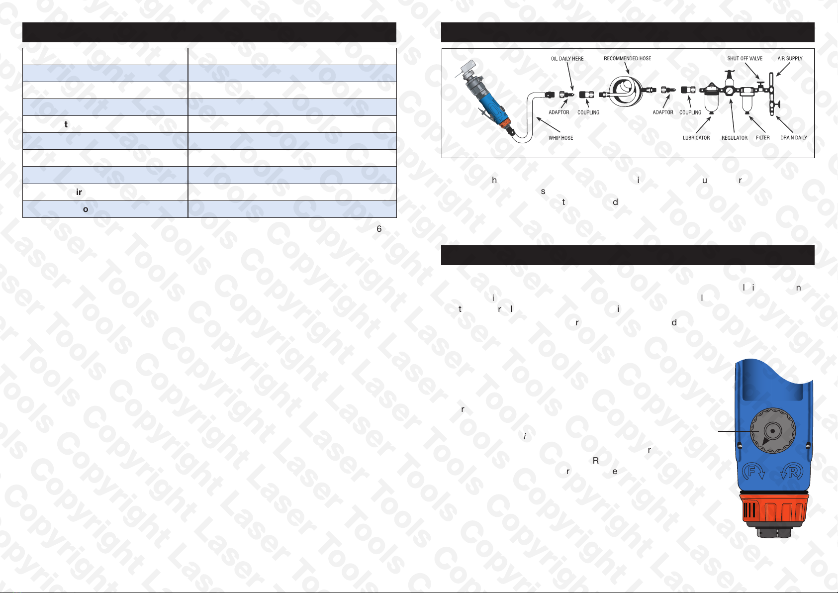
Components
ATrigger
BTrigger safety lock
CSpeed control
DForward/Reverse control
ERotating adjustable exhaust port
FAir inlet
GFlexi-Head securing clamp
HCutting wheel guard
IGuard position lock screw
JGuard securing screw
KCutting disc (available separately)
LCutting wheel securing nut key
MSpindle lock key
N4mm Hex key
Fig 1
BA C
F
D
GH I
JK
E
L M N
4mm
Safety Precautions
• Eye and face protection plus heavy work gloves and suitable work clothing must be used.
A cutting wheel that breaks can cause very serious injury. Never wear loose clothing or
jewellery that could be trapped by moving parts.
• Ensure that every user reads and understands these instructions.
• Dust hazard: a suitable-grade dust mask or respirator must be used for any dust-
generating operations, particularly on glassfibre substrates.
• Vibration hazard: exposure to vibration can cause damage to nerves and blood supply of
the hands and arms. If you experience numbness, tingling, pain or whitening of the skin in
fingers or hands, stop using the tool immediately.
• Noise hazard: unprotected exposure to high noise levels can cause hearing loss and
tinnitus (ringing or buzzing in the ears). Wear suitable ear protection as required by
occupational health and safety regulations.
• Do not attempt to remove or change a cutting wheel until the tool has been disconnected
from the compressed air supply.
• Correct cutting wheel mounting is necessary to prevent injury from broken wheels. Do not
use chipped or cracked cutting wheels.
• Cutting wheels should fit cleanly over the spindle to prevent stress at the hole. Do not use
any additional washers or spacers to mount the cutting wheel.
• Never use a cutting wheel that is marked and specified with a speed lower than the tool
speed.