SAHINLER HPK 665 User manual

U
U
US
S
SE
E
ER
R
R’
’
’S
S
S
M
M
MA
A
AN
N
NU
U
UA
A
AL
L
L
M
M
MO
O
OD
D
DE
E
EL
L
L
H
H
HP
P
PK
K
K
6
6
65
5
5
H
H
HY
Y
YD
D
DR
R
RA
A
AU
U
UL
L
LI
I
IC
C
C
S
S
SE
E
EC
C
CT
T
TI
I
IO
O
ON
N
N
B
B
BE
E
EN
N
ND
D
DI
I
IN
N
NG
G
G
M
M
MA
A
AC
C
CH
H
HI
I
IN
N
NE
E
E
İ
İ
İz
z
zm
m
mi
iir
r
r
Y
Y
Yo
o
ol
llu
u
u
2
2
22
2
2.
..k
k
km
m
m
M
M
Mü
ü
üm
m
mi
iin
n
n
G
G
Ge
e
en
n
nc
c
co
o
oğ
ğ
ğl
llu
u
u
C
C
Ca
a
ad
d
d.
..
1
1
16
6
62
2
28
8
85
5
5
B
B
BU
U
UR
R
RS
S
SA
A
A
/
//
T
T
TU
U
UR
R
RK
K
KE
E
EY
Y
Y
T
T
Te
e
el
ll:
::
+
+
+9
9
90
0
0-
-
-2
2
22
2
24
4
4-
-
-4
4
47
7
70
0
00
0
01
1
15
5
58
8
8
(
(
(6
6
6
l
lli
iin
n
ne
e
es
s
s
p
p
pb
b
bx
x
x)
)
)
F
F
Fa
a
ax
x
x:
::
+
+
+9
9
90
0
0-
-
-2
2
22
2
24
4
4-
-
-4
4
47
7
70
0
00
0
07
7
77
7
70
0
0
W
W
We
e
eb
b
b:
::
w
w
ww
w
ww
w
w.
..s
s
sa
a
ah
h
hi
iin
n
nl
lle
e
er
r
rm
m
me
e
et
tta
a
al
ll.
..c
c
co
o
om
m
m
E
E
Em
m
ma
a
ai
iil
ll:
::
i
iin
n
nf
ffo
o
o@
@
@s
s
sa
a
ah
h
hi
iin
n
nl
lle
e
er
r
rm
m
me
e
et
tta
a
al
ll.
..c
c
co
o
om
m
m
S
S
Sp
p
pa
a
ar
r
re
e
e
p
p
pa
a
ar
r
rt
tts
s
s
&
&
&
s
s
se
e
er
r
rv
v
vi
iic
c
ce
e
e:
::
s
s
se
e
er
r
rv
v
vi
iic
c
ce
e
e@
@
@s
s
sa
a
ah
h
hi
iin
n
nl
lle
e
er
r
rm
m
me
e
et
tta
a
al
ll.
..c
c
co
o
om
m
m

C E D E C L A R A T I O N
We as
ŞAHİNLER METAL MAKİNE END. A.Ş.
İzmir Yolu 22.km
Mümin Gençoğlu Caddesi
Bursa / TÜRKİYE
confirm that the machine
H
HP
PK
K
6
65
5
Serial Number :
Production Year :
complies with
and the machine also harmonized with the standards
DIN EN 60204 Part 1
Name : Mustafa PINARBAŞI
Position : Production Director
BURSA, on..............................
E
E
EC
C
C
M
M
MA
A
AC
C
CH
H
HI
I
IN
N
NE
E
ES
S
S
D
D
DI
I
IR
R
RE
E
EC
C
CT
T
TI
I
IV
V
VE
E
E
9
9
98
8
8
/
/
/
3
3
37
7
7
/
/
/
E
E
EC
C
C
r
r
re
e
ep
p
pl
lla
a
ac
c
ce
e
ed
d
d
w
w
wi
iit
t
th
h
h
E
E
EC
C
C-
-
-D
D
Di
iir
r
re
e
ec
c
ct
t
ti
iiv
v
ve
e
es
s
s
9
9
91
1
1
/
//
3
3
36
6
68
8
8
/
//
E
E
EW
W
WG
G
G
a
a
an
n
nd
d
d
9
9
93
3
3
/
//
4
4
44
4
4
/
//
E
E
EW
W
WG
G
G
a
a
an
n
nd
d
d
9
9
93
3
3
/
//
6
6
68
8
8
/
//
C
C
CE
E
EE
E
E
E
E
EC
C
C-
-
-L
L
Lo
o
ow
w
w
V
V
Vo
o
ol
llt
t
ta
a
ag
g
ge
e
e
7
7
73
3
3
/
//
2
2
23
3
3
/
//
E
E
EW
W
WG
G
G
E
E
EC
C
C-
-
-N
N
No
o
oi
iis
s
se
e
e
L
L
Le
e
ev
v
ve
e
el
ll
D
D
Di
iir
r
re
e
ec
c
ct
t
ti
iiv
v
ve
e
es
s
s
8
8
86
6
6
/
//
1
1
18
8
88
8
8
/
//
E
E
EW
W
WG
G
G

- 1 -
CONTENTS Page
Content 1
General Notes 2 - 3
General Warranty Terms 4
General Safety Terms 5
Danger Zones 6
Transporting Lifting and Carrying 7
Foundation and main dimensions 8 - 9
Operating HPK 65 as horizontal 10
HPK 65’s Technical Properties 11
Capacity Chart For HPK 65 12
Operating the machine 13
Standard equipments for HPK 65 14
Bending Operations 15 - 16
Flat bar bending 17
Pipe Bending 18
Leg-In and Leg-Out Rolling 19
T – U - I Section Rolling 20 - 21
Maintenance and Lubrication 22 - 24
Lubricating the guide rollers 25
Hydraulic Plans and Parts List 26
Standard Roller 27
Main Part Lists 28 - 40
Electric Schemes

2
GENERAL NOTES
1. Introduction
Thank you for choosing a Şahinler Sheet / Metal Working Machine. We are proud to have you
in our long list of satisfied customers all over the world.
This User’s Manual is absolutely for your safety and is essential for the machine to have a
long production life. As long as you keep up with our Manual you will be able to run your machine
smoothly and safely. Keep in mind that the machine is designed absolutely to perform maximum safe-
ty and for efficient working.
In this Manual you can find instructions and information about:
Correct installations of the machine
Description of the functional parts of the machine
Set-up and start-up adjustments
Correct standard and scheduled maintenance
Simple safety regulations and accident prevention.
Therefore, as far as the user’s safety is concerned, in this handbook the possible risks
connected with machine operation are pointed out as follows:
ATTENTION: Showing the risks of accident, if instructions are not followed.
WARNING: Showing the probable damages to the machine or equipment, if the
instructions are not strictly followed.
NOTE: It gives useful information.
It is certainly necessary that the operator should read and understand all the ATTENTION,
WARNING notes specified in this Manual before starting with operation of the machine and before any
lubrication or maintenance intervention.
On all steps of installation, operation and maintenance safety must be your first concern for
the protection of yourself, other users and the service of the machine.
In case of any failure please first refer to this Manual, and then if a solution cannot be found
contact first of all the distributor where you purchased our product. Do not forget to refer to the

2
drawings and the numbers for any spare part needed or to define any problem. Make sure you have
the serial number and production year of the machine.
Our technical staff will make their best to help you in the most convenient way.
2. Transport
As soon as you receive the machine, check for any visible transport damages. Should there
be any visible damages; report it straight away to the transporter company and of course Şahinler
Metal Mak. End. A.Ş. or your supplier.
Remove any protective crates around the machine and read the instructions on related
chapters of this Manual carefully to set up the machine. If the machine is damaged while transport,
immediately take some photographs for insurance claims.
Take precautions while loading / unloading or moving the machine to avoid any injuries. Refer
also to related chapter of this Manual for the best way of handling the machine.
3. Electrical Information
All necessary connection procedure can be found on this Manual. Do not try to connect the
machine before reading these procedures and fully understanding the drawings. For any unclear
matters get in touch with Şahinler Metal Mak. End. A.Ş. or any of the Şahinler distributors. Have the
machine connected by a qualified electric technician. For, as we made clear in the “general conditions
of guarantee”, under no circumstances installing mistakes, one of which is the electrical connection
mistake, can be covered in the guarantee agreement. Always turn off power before making any
connections or disconnecting the machine.
4. Maintenance
Your machine is designed and produced to work efficiently and smoothly. To achieve this you
should also take care while operating the machine. Regard Maintenance sections to have the longest
life from your machine. Try and use original spare parts where necessary and most importantly do not
overload the machine or do not make any unauthorized modifications.
5. Safety
Take all precautions possible to avoid any personal injury while using the machine. Keep in
mind to protect the third party people around the machine. Refer to safety instructions.

4
GENERAL WARRANTY TERMS
Your machine is covered by manufacturer’s guarantee for a period of 12 months from the date of
purchase against manufacture defects. The warranty period does not exceed 18 months from the
date of delivery from the manufacturer’s factory.
Warranty covers only manufacture defective parts and / or components that are reported as
“defective” by a Sahinler Technician or the Agent Technician and must be reported to Sahinler in
writing by fax or email.
The manufacturer is responsible for the supply of free of charge spares only and cannot be held
responsible for loss of work.
Shipping and customs fees for the spare part must be paid by the end-user.
If a technician travel is necessary Sahinler will not charge for labor and workmanship costs but the
customer must pay traveling and accommodation charges.
A Warranty claim does not relieve the Customer from payment obligations.
The Customer can not ask or demand any reimbursement of damage nor the Customer will have
the right to extend or delay payment obligations nor the cancellation of order and the refunding of
damages as the guarantee is given for the defective parts of the machine and not for the job.
Note: All warranty claims must be applied with the Model, Serial Number and the
Manufacture Year of the machine.

5
GENERAL SAFETY TERMS
1. Machine’s Safety Accessories and Accident Prevention Terms
The machine is provided with fixed shelters for the protection of all gears. But some mobile
parts, because of their shape for the bending processing cannot be protected within a case.
However, safety is guaranteed by the machine features and by the use of “human presence”
controls.
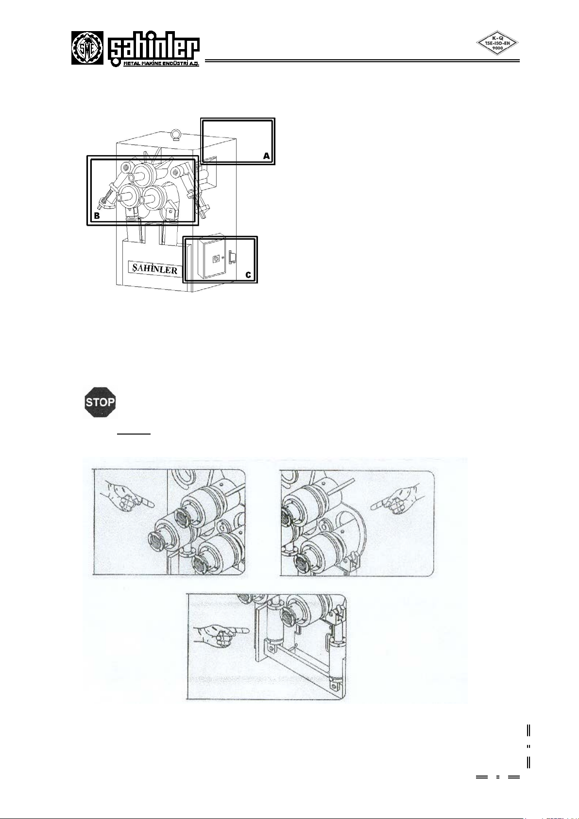
The machine is controlled by means of foot-pushed buttons present at the downside of the Mo-
bile Control Panel. During operation the specified safety distance must always be observed.
There is a red mushroom emergency button at the upside of the Mobile Control Panel to stop
all the machine activity by disabling the electric supply until released. In case of an extraordi-
nary situation, please push this button straight away.
No other persons except for the qualified and well-trained operator should be allowed to use
the machine and to be present in the working area of the machine.
Any damaged or defective connections to the different energy supplies must be replaced.
All interventions concerning installation, start-up, change of equipment, use, change to the use
and the operation, regular maintenance, inspection and periodical maintenance can be per-
formed only after disabling the machine according to relevant chapter of this handbook.
For any intervention to change the machine’s use, please contact to Şahinler Metal Mak. End.
A.Ş. previously and ask for their written approval.
2. Abnormal Conditions
In order to avoid unusual working conditions, in the following several recommendations to the
operator are listed. Also, do not forget that this machine can be used only in the conditions presented
in this operation and maintenance handbook.
Before connecting the machine double-check electrical connections read the instructions care-
fully. For, almost 65% of the failure reports we receive are based on either wrong electric con-
nection or use in contradiction to the User’s Manual.
Avoid the approach of persons to the operator while the machine is running.
Loading and unloading of the material should be done according to the instructions of this
handbook.
During the bending process avoid holding material with the hand.
Never wear garments with loose parts, which may be dragged by the machine parts, long loose
hair, necklaces, rings etc.
Never use goods except for the allowed ones as operational materials.
Never run the machine without safety devices.
Don’t climb on the machine.
If the customer wants to install on the HPK 65 machine a piece of equipment, which has not
been supplied by Şahinler Metal Mak. End. A.Ş., the compliance with the safety conditions ex-
plained here has to be checked.
The machine cannot be installed and used in corrosive environments.
The machine must always be operated with one qualified operator who has the required knowl-
edge to use this machine properly.

6
DANGER ZONES AROUND THE MACHINE
A- Inside the machine where the hydraulic and power systems are located
B- The main work area of the machine around the pinch points of rolls
C- Electric Box on the side of the machine
POSSIBLE INJURY AREAS
Warning :
NEVER PLACE ANY PART OF YOUR BODY TO THESE AREAS WHILE THE MACHINE IS
RUNNING

7
TRANSPORT AND LIFTING OF THE MACHINE
The machine weight is approximately 750 kg. Use necessary cranes and lift as shown. Please take
extra care during lifting and moving. If necessary consult with specialized companies for lifting.
Figure 1
OPENING THE PACKAGE
If any visible damage exist on the machine when you receive the machine immediately
informs the dealer or manufacturer. Also never forget to state the visible damage on transport documents.
The packing material is completely safe and do not consist any environmentally dangerous
articles. However they must be kept out reach of children as some nylon products in packing may
cause suffocation if used as a toy etc.
APPROX MACHINE WEIGHT 750 Kg.

8
FOUNDATION AND MAIN DIMENSIONS OF THE MACHINE
Note: The manufacturer doesn’t accept any responsibility for damages due to the
nonobservance of the above specifications.
Figure 1,2 shows the main dimensions of the machine. Figure 3 shows the work area This
area is illustrated considering the machine located horizontally. If you operate it vertically, then the
borders will be the same. Vertical and horizontal positions are shown figure 4. For vertical or
horizontal operations the machine must be placed smooth as shown and must be bolted to the
ground.
Note: All machines must be carefully adjusted before operation
with a water gauge.
Figure
2
Figure
1

9
Note: Always leave necessary safety distance
Figure 3
Figure 4

10
OPERATING HPK 65 AS HORIZONTAL
Before positioning the machine it is necessary to leave enough working area for the proper
bending operations such as extraction of the cylindrical profile, feeding of the semi product, bending of
big diameters.
If you have no alternative to install the machine in a broad area but a low-height area, then
there is a solution to this problem as shown in figure 2.
To set the machine horizontally follow these steps:
Wrap a belt capable of carrying at least 4 tons around the top roll’s shaft
(shown by in fig. 1).
Lift the machine slowly by means of a forklift or a crane with hook.
After that, slowly lower the machine.
Attention: Do not wrap the belt around the top roll adjustment screw so that it may be bent
or its teeth may be damaged.
Figure 1
Figure 2

11
HPK 65’s TECHNICAL PROPERTIES
As a superior model in its own class the HPK 65 is equipped with a powerful motor and a low
noise reduction gearbox, which gives the machine power to bend with ease. The digital Read-Outs on
bottom rolls give higher accuracy and increase the efficiency. By using Mobile Control Panel you can
easily and safely bend the required materials. General Technical Information of HPK 65 is given
below.
STANDART SPECIFICATIONS
Three Rolls are Powered
Steel Construction Frame
Rolls Shafts are Special Steel Material
Rolls are Hardened and ground
Horizontal and Vertical Working Position
Brake Motor Equipped
Standard and Hardened Rolls
Mobile Control Panel
3-Axis Mechanical Lateral Angle Guide
Rolls
User’s manual
Brake motor
Digital Read-outs ( 2 pcs. )
SPECIAL FEATURES
SAFETY UNITS
Emergency Button on Mobile Control
Panel
Various DANGER signs around the
machine
Overload Circuit – Breaker
Safety lock on main power supply.
Note: Due to various safety
regulations, the specifications presented
here can change from country to country
without prior notice. Above dimensions
and other characteristics can also change
without prior notice due to our constant
improvements on our products.
Please note that some, angle materials and all pipe materials need special rolls. Please ask for
special rolls if necessary.
MODEL: HPK 65
Shaft Diameters
∅
mm
50
Roll Diameters
∅
mm
180
Working speed
m/min
5
Motor Power
KW
3
Weight
kg.
750
Length
Mm
820
Width
Mm
645
Height
mm
1045
Pipe, Tube and Profile Bending
Note : Machine dimensions are approximate

12
Warning: Do not feed profiles having a higher thickness than specified for the
capacity of the machine.
Do not feed more than one piece at a time.
Do not use the machine for any other scope the one for which it has been designed.
CAPACITY CHART FOR MODEL HPK 65
No Profile type Maximum size Min. int
∅
Notes
1
60 x 10
20 x 5 500
250 Standard rolls
2
80 x 20
80 x 5
500
250
Standard rolls
3 32 x 32
12 x 12 400
220 Standard rolls
4
∅
35
∅
10 350
200 Optional rolls
5
∅
60x2
∅
15x1,5 600
200 Optional rolls
6
∅
2”x3,91
∅
½”x2,77
350
200
Optional rolls
7 50x25x3
20x15x2 450
250 Optional rolls
8 45x45x3
20x20x2
550
250
Optional rolls
9 60x60x6
30x30x4
650
350
Optional rolls
10 50x50x5
30x30x4 550
350 Optional rolls
11 60x60x7
20x20x3 550
250 Standard rolls
12 50x50x6
20x20x3
500
250
Standard rolls
13
60x60x7
20x20x3
500
250
Standard rolls
14 UPN 80
UPN 30
450
250
Standard rolls
15 UPN 65
UPN 30
450
250
Standard rolls
16 IPN 80 600 Optional rolls
•We reserve the right to make changes without notice
•Capacities are given for ST 42 material.

13
OPERATING THE MACHINE
The Mobile Control Panel is your interface with the machine and it is very easy to operate the
machine.
Here are the names of the buttons on Control Panel:
1. Power On Key Switch - Safety Key Switch. When the machine is not in use please remove the
key to avoid unauthorized operation
2. Rolls rotation button – right
3. Left bottom roll – Up and down
4. Power on indicator – When on this indicates the machine Main Power Switch is on and ready to start
5. Emergency stop
6. Start Button – To start to hydraulic pump and all functions
7. Rolls rotation button - left
8. Right bottom roll – up and down
9. Digital displays - for Roll Left and Right
Turn on the Main Switch on the Machine Electric Panel
Turn on the Main Power Key Switch (No.1)
Check that the Emergency Button (No.5) is released
Push Start Button (No.6)
You should hear the hydraulic system activating
Warning
If the rolls do NOT move at this point it means that the electric cables have been connected
inverse. immediately stop the machine and reverse the electric cables.
.
Try rotating the rolls (No.2 and 7)
If everything works properly you can proceed with bending
A. Left roll
B. Right roll
C. Top roll

14
STANDARD EQUIPMENTS FOR HPK 65
ADJUSTING THE GUIDE ROLLERS
The Guide Rollers are very important on the machine as they directly affect the outcome of
any bending to be smooth and accurate.
There are three axes movements to this system
Y - Vertical Drive
X – Horizontal Drive
Z – Radial Drive
See picture ( Mechanic Guide ) below to understand axes movements
Warning:
Do NOT place any part of your body on the Guide Rollers while adjusting them.
Be careful to other people around the machine who may be in danger while adjusting.
Y – Axis
Up / Down
X – Axis
Forward/Backward
Z – Axis
Radial/Movement

15
BENDING OPERATIONS
NORMAL BENDING OPERATIONS
You can feed the material to the machine from both sides. Use the digitalis to adjust the rolls.
Also adjust the guide rollers to achieve a better accuracy and better finish.
To give an idea on a simple bending following steps can be taken. Please note that you will
get better quality from the machine with experience.
IMPORTANT
If the material to between three is long we recommend a material support/feed unit for higher
accuracy. One feeder/support in each 2 meters should be sufficient.
Place the material between the three rolls on such a position that the material will be parallel to the
ground and touching all three rolls at the same time. This position is called zero position.
Both bottom rolls must be equally away from the top roll. This rule is applied the same for the
machine in Vertical Position (figures 1 and 2) .
Raise one of the rolls depending on the direction of the rolling. And start turning the rolls and when
the end of the material reaches between all three rolls raise the other roll and bend in the opposite
direction.
By following the above step you can bend until it reaches the diameter required.
With the optional equipment of Digital read-outs you can always know the exact position of the
rollsj
SPIRAL(HELIX) BENDING
It is rather difficult to make spiral bending and needs experience. The following steps can be
taken to start with;
.
Arrange the rolls in a position so that they are 3-4 % smaller than the required diameter (Figure 4)
The guide roller A (figure 5) must be adjusted until the required diameter
For full diameter bending cut the material as
π
times the diameter. Remember to leave
necessary cut of length. Where at the and of bend two flat parts meet cut of the flat parts and
bend until the edges meet.
In tight spirals where the edge tends to go inside the spiral use a lever to overcome this tendency
(Figure 3)
On arc bending use the guide roll A (figure 5) to obtain the necessary finish arc. If you are bending
a pipe the roller A needs to be replaced with a pipe roller also.
FIGURE 1
FIGURE 2

16
During the bend of thin profiles or thin material due to intense bending power a wave may occur on the
finished material. Use the nut on Roller B (figure 5)to avoid this problem.
ADJUSTING INSTRUCTIONS
With the HPK 55 machine one set of standard rolls is supplied .If these are arranged and
adjusted in combinations most of the profiles and some angle material can be bent.
Adjustment of rolls and correct positioning of the rolls is critical for the efficiency of the
machine. Some of the basic references are
Expansion of the rolls after long term use due to thermal over heat.
Position of the material between the rolls.
Position of the spacers.
Adjusting top roll coupling if necessary
Positioning using the scale or Digital read-out
When bending too tight material or during serial production you may notice a swelling in the
inside diameter of the material. This is due to top roll which expands due to overheat but does not
move up. Moving the top roll a little up will solve the problem.
On bending where more power is needed the coupling of the top roll can be loosened to
achieve greater rotation or you can use larger top roll so that the material ends are rigidly pushed
between the rolls.
Here the rolls and the spacers are numbered below. Use these numbers to position the roll
according to the drawings on following pages.

16
Clutch System;
If the top roll stops, while lower rolls are turning, than the pressure springs must be tightened a
bit. To make this you have to screw the setscrews shown in Step2.
The balance of the clutch system is shown below step by step.
Step1 Step2
1. Open the back cover.
2. Screw them through arrow direction with an ally key.(6)
Note : Keep to tighten it until top roll begins to turn.

17
FLAT BAR BENDING
You can bend all kinds of flat bars the easy way or the hard way by adjusting the rolls as
necessary. Some examples are below. See figures 1-2.AIso the use of guide rollers(X) is strongly
recommended. figure 1 shows how to bend the hard way for high end bars and short and small bars.
As always experience will help you achieve better results.
BENDING PROFILES
If the profiles are thick walled you can use the rolls as shown in figures 3-4-5. If the wall
thickness is thin then special rolls must be used.
Bending profiles accurately is somewhat difficult due to tendency of the material to deflect
(figure 6) A good recommendation is to fill the profile with a filling material which will resist the
bending forces and will help the profile to keep its wall integrity. It must also be noted that this filling
material must be easily removable after operation.
Table of contents