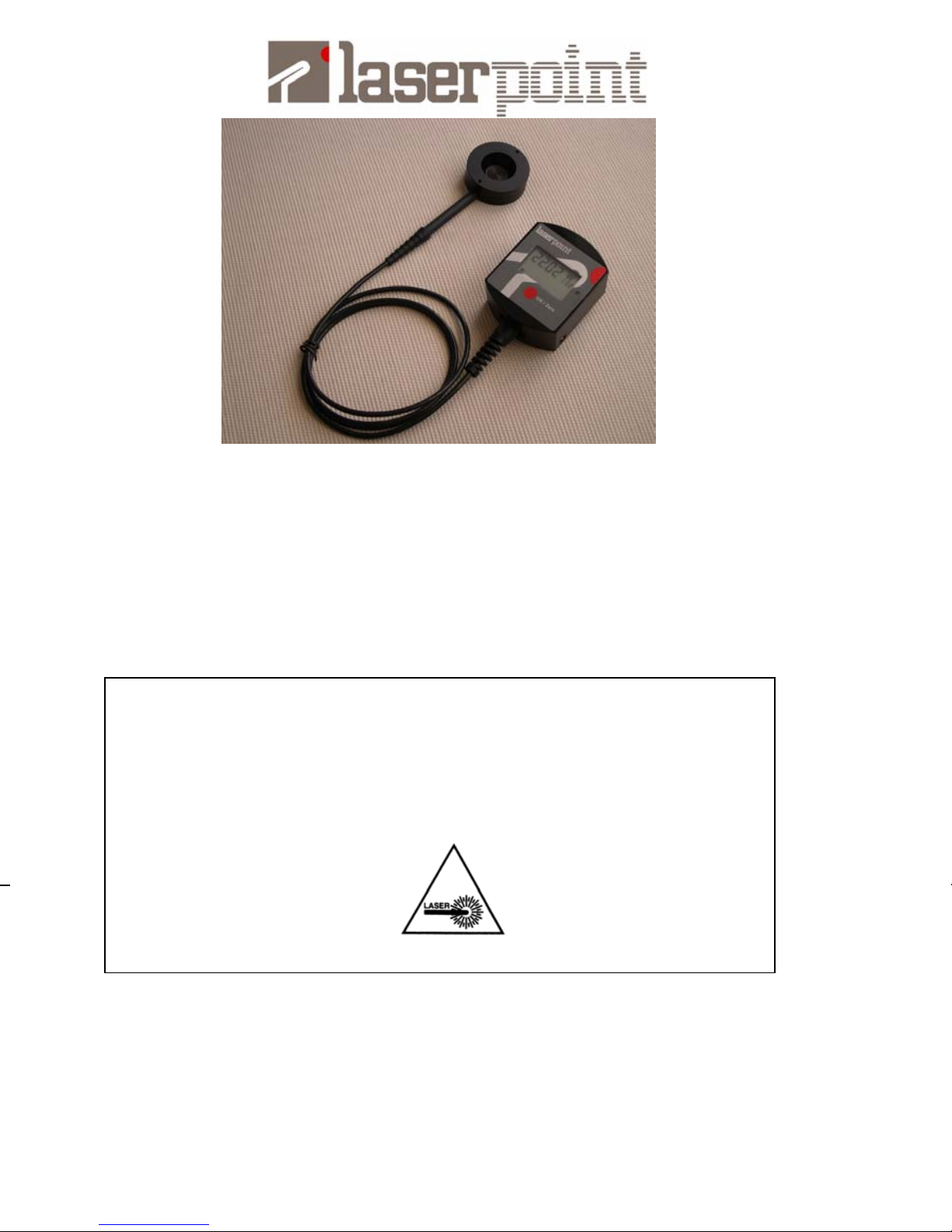
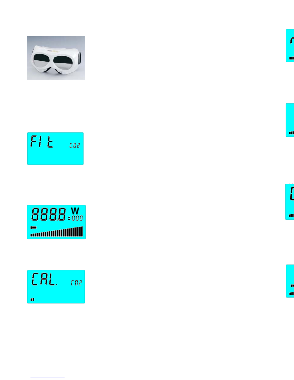
LaserPoint Fit User manual

Technical Specifications (*):
(*) Specifications subject to change without notice.
(1) Individually compared against a NIST or PTB reference.
Warranty
All Laser Point instruments are warranted against defect in material and workmanship
for one year after invoice date. During the warranty period Laser Point will repair, or at
his sole option, replace at no charge components that prove to be defective, provided
the parts are returned, shipping prepaid, to Laser Point Customer Service.
This warranty does not apply if the instrument or any accessory has been damaged by
accident or misuse, or as a result of service or modification by other body than Laser
Point. No warranty is given by Laser Point on coatings and battery pack.
8
F
Fi
it
t
Instruction Manual
(Rev11- Nov 2008; Firm. vers.11)
1
Parameter Fit 50 Fit 200 Fit 500
Maximum Measurable Power (W) 50 200 500
Minimum Measurable Power @ ±3% Accuracy (W) 1.5 (1) 5
(1) 15 (1)
Absolute Minimum Measurable Power (W) 1.25 3 7.5
Maximum Laser Beam Diameter (mm) 20 20 25
Power density damage threshold @ full scale at YAG
wavelength (W/cm2 )
10000
Power density damage threshold @ full scale at CO2
wavelength (W/cm2 )
2500
Repeatability ±1%
ADC Resolution (W) ±0.06 ±0.25 ±0.60
Display Resolution (W) 0.01 0.1 0.1
Measurement Accuracy ±3%
Maximum allowable sensor head temperature (°C) 70
Time to measure and display data (s) 4
Power consumption in On status (mW) 26
Power consumption in Off status (µW) 25
Power supply (2x AA Batteries) (V) 3
Continuous operation without battery replacement (h) 200
Operating temperature range (°C) +10 to +40
Storage temperature range (°C) -10 to +60
Weight (body) (g) 336
Weight (sensor with cable) (g) 178 200 280
Size (head) DxH (mm) 56x20 56x25 66x30
Size (body) LxWxH (mm) 95x71x46
WARNING! The user of this instrument must be trained to the
use of power lasers and associated risks. LaserPoint is in no way
liable for any damage resulting from improper, careless or above
rated limits use of this instrument.

Declaration of Conformity
Application of Council Directive(s) : 89/336/EEC The EMC Directive
73/23/EEC Low Voltage Directive
Manufacturer’s Name : LaserPoint srl.
Manufacturer’s Address : LaserPoint srl- Via Burona, 51- Vimodrone-20090 Italy
Type of Equipment: Laser Power/Energy Meter
Model No.: FIT
Year of test & manufacture: 2004
Standard(s) to which Conformity is Declared:
EN 50081-1:1992 Emission generic standard - Part 1: Residential, commercial and light
industrial
EN 50082-2:1995 Immunity generic standard - Part 1: Industrial
Standard Description Performance
Criteria
EN 55022:1994
amendment 1: 1995
amendment 2: 1997
Limits and methods of measurement of
radio interference characteristics of
information technology equipment
Class B
EN 61000-4-2:1995
Electromagnetic compatibility (EMC) – Part
4: Testing and measurements techniques-
Section 4.2: Electrostatic discharge.
Class B
EN 61000-4-4:1995
Electromagnetic compatibility (EMC) – Part
4: Testing and measurements techniques-
Section 4: Electrical fast transient/burst
immunity.
Class B
I the undersigned, hereby declare that the equipment specified above conforms to the
above Directive(s) and Standard(s).
Place: Vimodrone –Italy _______________________________
Date : 01.10.04 Dr Luigi Argenti (Technical Director)
2
Notice to European Union Customers:
European Union Waste Electrical and Electronic Equipment (WEEE) Directive
2002/96/EC
The European Parliament will enforce new Directives in 2006 concerning the disposal
of electrical and electronic equipment such as the Monitoring and Control Instruments.
The regulations place responsibilities on the instruments supplier and the
purchaser/user.
One of the actions required by suppliers is to inform users of their obligations.
The present instrument has been assessed in accordance with the European Parliament
Directive2002/96/EC on Waste Electrical and Electronic Equipment, usually referred to
as the WEEE Directive.
The WEEE Directive requires that the instrument is disposed of at the end of its useful
life in an environmentally responsible manner. Parts and materials that can be re-used
and/or re-cycled have been identified in order that the use of new resources and the
amount of waste going for landfill can be minimised.
The WEEE Directive requires that if you are replacing the instrument with a new
equivalent product from the original supplier, then that supplier can collect the old item
without cost to yourself. It is emphasised that this no-cost return option is only
available when you purchase a new product of equivalent type that fulfils the same
function. Please inform your supplier of your wish to have the old instrument collected
when ordering the replacement.
If you wish to dispose of the instrument without replacing it then the appliance must not
be mixed with unsorted municipal waste. The crossed-out wheeled bin symbol on the
unit label or unit packaging, as shown in the table below, indicates this requirement.
You must ensure that the instrument is disposed of at an authorised treatment facility;
details can be obtained from your local council.
Your role is critical and will help to ensure that the Earth’s resources are maintained
and that as much re-usable and re-cyclable material as possible is processed. It will also
ensure that landfill volume requirements are kept at a minimum and that hazardous
materials are not buried thereby providing potential future problems for the
environment and human health.
Wheeled bin symbol and description
The symbol apply to all LaserPoint electronic products placed
on the European Market after August 13, 2005.
LaserPoint will affix the wheeled bin symbol with a bar to
appropriate products. The bar indicates that the product was
placed on the market after August 13, 2005.
The WEEE Directive comes into force in January 2006.
7

9-Out of Range Notice
When the head is exposed to a source exceeding its
full scale, the LCD shows four short lines instead of a
numeric value.
10-Wavelength Selection
To select the wavelength of operation (e.g. from CO2 to
YAG), go back to Paragraph 2 (shut the instrument off),
but keep the ON/Zero button pushed until the wavelength
change appears on the display (this step takes
approximately 7 seconds). At this point release the button and the instrument is
ready for a new measurement.. The displayed value is the last recorded power
measurement carried out at this wavelength setting.
11-Customer’s calibration
This instrument can be re-calibrated by the user to
match a custom reference. Remove the plastic cover of
the adjustment switch located at the right side of the
instrument body. Zero the instrument as indicated in
Paragraph 2 of this Operation Section and afterwards
carry out a measurement of a known laser source. Shift the switch on + or – if
you need to increase or decrease the reading displayed on the LCD to match your
reference. This is done by limited pushes on the ON/Zero key, until the desired
power value is achieved on the display. Reset the switch to its middle position
CAL and re-cap. The instrument is ready for new measurements.
6
Calibration
Model: Fit ______ Serial number: ______________
Date of Calibration: _______________
Wavelength 1: _______________nm
Reference Power :________________W Measured Power: _________________W
Wavelength 2: _______________nm
Reference Power :________________W Measured Power: _________________W
LaserPoint certifies that, at the time of calibration, the above listed instrument meets or
exceeds all technical specifications defined at page 8 of this Instruction Manual.
The above listed instrument has been calibrated using standard references traceable to
the National Institute of Standards and Technology (NIST) or Physikalisch Technische
Bundesanstalt (PTB).
This is not a Calibration Certificate for traceability purpose; such a Calibration
Certificate can be quoted on demand.
Important - For Customer Use Only
The reference setting of this instrument can be matched by user to a custom own
reference by means of the instructions reported at Paragraph n.11 of the Operation
Section of this Manual.
3

Operation Section
1-Safety
Take all the required safety procedures needed when
working with laser beams and wear protection glasses all
the time! The laser beam must hit ONLY the sensor head
front side. Avoid to incidentally expose the protected
stainless steel stem to the laser beam as dangerous back-
reflections can be produced! Never touch the sensor head as this part can reach
70°C of temperature!
In the case the laser power density is close to the damage threshold of the head
absorber coating, damages like coating discoloration or underlying metal melting
could occur. In both cases consult LaserPoint.
2-Starting the Instrument
To switch on the instrument, keep the ON/Zero button
pushed until the LCD shows the Fit Model (Fit 50, Fit 200,
Fit 500 shown in 2 steps), then release it (this step takes
approximately 2 seconds). The instrument will also display one of the 2 available
laser wavelengths: e.g. CO2. The wavelength displayed the first time is random;
to change it refer to Paragraph 10 of this section.
3-Auto-check Cycle
When the ON/Zero button is released, the instrument starts
an auto-check cycle during which both circuit and display
are controlled and reset. During this cycle, the LCD shows
all available segments of alphanumeric characters and the
bar graph at full scale. Upon completion of this cycle, the LCD displays the last
recorded value of measured power.
4-Zeroing/Resetting
Before starting the first measurement or a new one, the
instrument needs to be zeroed; to do so, just push and soon
release the ON/Zero button. After the LCD has displayed
“CAL”, the lateral LED turns steady green and “FIT”
blinks. Any previously recorded value is zeroed and the instrument is ready to
measure.
An automatic Zero is performed by Fit after every measurement.
4
5-Measurement Cycle
Check the laser shutter is closed; align the probe to the
laser beam path and start the measurement cycle by opening
the laser shutter. Avoid taking measurements during laser
warm up or beam instabilities.
The measurement starts automatically. During the acquisition time, “RUN” and the
LED both blink for approximately 5 seconds. The bar graph indicates the head
temperature on an arbitrary scale.
6-Measurement Display
As soon as the measurement is over the LED turns into
steady red. Remove the probe from the laser beam: the
display shows the actual power, and the remaining thermal
capacity. If the bar graph is below full scale, one or more
measurements can be carried out before the sensor head needs to be cooled.
Approximately after 10 seconds the LED automatic shuts off. The FIT performs an
automatic Zero and the LED turns steady green. The LCD shows the last measured
power value . Return to Par.5 for a new measurement
7-Cooling the Head
Should the probe reach its limit temperature, the LCD
shows “ COOL” and the LED blinks red. Use
spontaneous or air forced cooling. Never use liquids!!
As soon as the temperature returns below its maximum
allowable limit, the LCD displays the last measured power value.
Warning: sudden cool downs and subsequent strong temperature variations on
the head may cause a re-start of instrument and spurious measurements.
8-Auto Off /Battery Warning
When the battery pack is getting exhausted, its symbol
pops up on the LCD to warns that approx. 10 hours of
residual power remain. Note: to increase the battery life,
the instrument automatically switches off after 5 minutes
of stand by operation.
To retrieve the last recorded value, return to Paragraph 2. After the internal auto
check cycle, the display will show the last measured value.
To intentionally shut the instrument off, keep the ON/Zero button pushed until the
LCD shuts off (this takes approximately 4 seconds).
5

9-Out of Range Notice
When the head is exposed to a source exceeding its
full scale, the LCD shows four short lines instead of a
numeric value.
10-Wavelength Selection
To select the wavelength of operation (e.g. from CO2 to
YAG), go back to Paragraph 2 (shut the instrument off),
but keep the ON/Zero button pushed until the wavelength
change appears on the display (this step takes
approximately 7 seconds). At this point release the button and the instrument is
ready for a new measurement.. The displayed value is the last recorded power
measurement carried out at this wavelength setting.
11-Customer’s calibration
This instrument can be re-calibrated by the user to
match a custom reference. Remove the plastic cover of
the adjustment switch located at the right side of the
instrument body. Zero the instrument as indicated in
Paragraph 2 of this Operation Section and afterwards
carry out a measurement of a known laser source. Shift the switch on + or – if
you need to increase or decrease the reading displayed on the LCD to match your
reference. This is done by limited pushes on the ON/Zero key, until the desired
power value is achieved on the display. Reset the switch to its middle position
CAL and re-cap. The instrument is ready for new measurements.
6
Calibration
Model: Fit ______ Serial number: ______________
Date of Calibration: _______________
Wavelength 1: _______________nm
Reference Power :________________W Measured Power: _________________W
Wavelength 2: _______________nm
Reference Power :________________W Measured Power: _________________W
LaserPoint certifies that, at the time of calibration, the above listed instrument meets or
exceeds all technical specifications defined at page 8 of this Instruction Manual.
The above listed instrument has been calibrated using standard references traceable to
the National Institute of Standards and Technology (NIST) or Physikalisch Technische
Bundesanstalt (PTB).
This is not a Calibration Certificate for traceability purpose; such a Calibration
Certificate can be quoted on demand.
Important - For Customer Use Only
The reference setting of this instrument can be matched by user to a custom own
reference by means of the instructions reported at Paragraph n.11 of the Operation
Section of this Manual.
3

Declaration of Conformity
Application of Council Directive(s) : 89/336/EEC The EMC Directive
73/23/EEC Low Voltage Directive
Manufacturer’s Name : LaserPoint srl.
Manufacturer’s Address : LaserPoint srl- Via Burona, 51- Vimodrone-20090 Italy
Type of Equipment: Laser Power/Energy Meter
Model No.: FIT
Year of test & manufacture: 2004
Standard(s) to which Conformity is Declared:
EN 50081-1:1992 Emission generic standard - Part 1: Residential, commercial and light
industrial
EN 50082-2:1995 Immunity generic standard - Part 1: Industrial
Standard Description Performance
Criteria
EN 55022:1994
amendment 1: 1995
amendment 2: 1997
Limits and methods of measurement of
radio interference characteristics of
information technology equipment
Class B
EN 61000-4-2:1995
Electromagnetic compatibility (EMC) – Part
4: Testing and measurements techniques-
Section 4.2: Electrostatic discharge.
Class B
EN 61000-4-4:1995
Electromagnetic compatibility (EMC) – Part
4: Testing and measurements techniques-
Section 4: Electrical fast transient/burst
immunity.
Class B
I the undersigned, hereby declare that the equipment specified above conforms to the
above Directive(s) and Standard(s).
Place: Vimodrone –Italy _______________________________
Date : 01.10.04 Dr Luigi Argenti (Technical Director)
2
Notice to European Union Customers:
European Union Waste Electrical and Electronic Equipment (WEEE) Directive
2002/96/EC
The European Parliament will enforce new Directives in 2006 concerning the disposal
of electrical and electronic equipment such as the Monitoring and Control Instruments.
The regulations place responsibilities on the instruments supplier and the
purchaser/user.
One of the actions required by suppliers is to inform users of their obligations.
The present instrument has been assessed in accordance with the European Parliament
Directive2002/96/EC on Waste Electrical and Electronic Equipment, usually referred to
as the WEEE Directive.
The WEEE Directive requires that the instrument is disposed of at the end of its useful
life in an environmentally responsible manner. Parts and materials that can be re-used
and/or re-cycled have been identified in order that the use of new resources and the
amount of waste going for landfill can be minimised.
The WEEE Directive requires that if you are replacing the instrument with a new
equivalent product from the original supplier, then that supplier can collect the old item
without cost to yourself. It is emphasised that this no-cost return option is only
available when you purchase a new product of equivalent type that fulfils the same
function. Please inform your supplier of your wish to have the old instrument collected
when ordering the replacement.
If you wish to dispose of the instrument without replacing it then the appliance must not
be mixed with unsorted municipal waste. The crossed-out wheeled bin symbol on the
unit label or unit packaging, as shown in the table below, indicates this requirement.
You must ensure that the instrument is disposed of at an authorised treatment facility;
details can be obtained from your local council.
Your role is critical and will help to ensure that the Earth’s resources are maintained
and that as much re-usable and re-cyclable material as possible is processed. It will also
ensure that landfill volume requirements are kept at a minimum and that hazardous
materials are not buried thereby providing potential future problems for the
environment and human health.
Wheeled bin symbol and description
The symbol apply to all LaserPoint electronic products placed
on the European Market after August 13, 2005.
LaserPoint will affix the wheeled bin symbol with a bar to
appropriate products. The bar indicates that the product was
placed on the market after August 13, 2005.
The WEEE Directive comes into force in January 2006.
7

Technical Specifications (*):
(*) Specifications subject to change without notice.
(1) Individually compared against a NIST or PTB reference.
Warranty
All Laser Point instruments are warranted against defect in material and workmanship
for one year after invoice date. During the warranty period Laser Point will repair, or at
his sole option, replace at no charge components that prove to be defective, provided
the parts are returned, shipping prepaid, to Laser Point Customer Service.
This warranty does not apply if the instrument or any accessory has been damaged by
accident or misuse, or as a result of service or modification by other body than Laser
Point. No warranty is given by Laser Point on coatings and battery pack.
8
F
Fi
it
t
Instruction Manual
(Rev11- Nov 2008; Firm. vers.11)
Laserpoint srl - Via Burona, 51 - 20090 Vimodrone (Milano) - Italy
Phone +39 02 27 40 02 36 - Telefax +39 02 25 02 91 61
www.laserpoint.it
1
Parameter Fit 50 Fit 200 Fit 500
Maximum Measurable Power (W) 50 200 500
Minimum Measurable Power @ ±3% Accuracy (W) 1.5 (1) 5
(1) 15 (1)
Absolute Minimum Measurable Power (W) 1.25 3 7.5
Maximum Laser Beam Diameter (mm) 20 20 25
Power density damage threshold @ full scale at YAG
wavelength (W/cm2 )
10000
Power density damage threshold @ full scale at CO2
wavelength (W/cm2 )
2500
Repeatability ±1%
ADC Resolution (W) ±0.06 ±0.25 ±0.60
Display Resolution (W) 0.01 0.1 0.1
Measurement Accuracy ±3%
Maximum allowable sensor head temperature (°C) 70
Time to measure and display data (s) 4
Power consumption in On status (mW) 26
Power consumption in Off status (µW) 25
Power supply (2x AA Batteries) (V) 3
Continuous operation without battery replacement (h) 200
Operating temperature range (°C) +10 to +40
Storage temperature range (°C) -10 to +60
Weight (body) (g) 336
Weight (sensor with cable) (g) 178 200 280
Size (head) DxH (mm) 56x20 56x25 66x30
Size (body) LxWxH (mm) 95x71x46
WARNING! The user of this instrument must be trained to the
use of power lasers and associated risks. LaserPoint is in no way
liable for any damage resulting from improper, careless or above
rated limits use of this instrument.
Table of contents
Other LaserPoint Measuring Instrument manuals