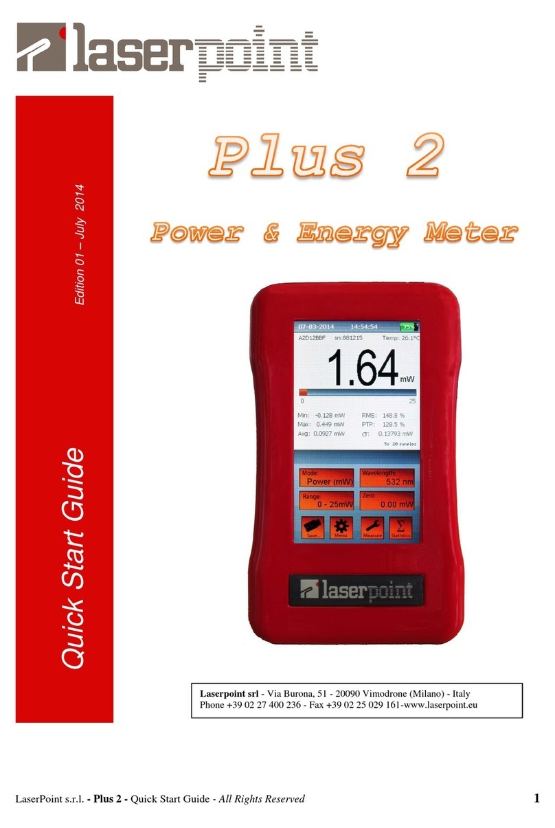
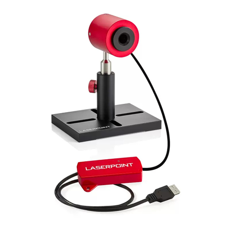
LaserPoint Plus 2 User manual

Laserpoint s.r.l. -Plus 2 - Quick Start Guide - All Rights Reserved 1
Quick Start Guide
Edition 2 –September 2014
Laserpoint srl - Via Burona, 51 - 20090 Vimodrone (Milano) - Italy
Phone +39 02 27 400 236 - Fax +39 02 25 029 161- www.laserpoint.eu

Laserpoint s.r.l. -Plus 2 - Quick Start Guide - All Rights Reserved 2
1.
Q
UICK
I
NTRODUCTION
Plus 2 is a handheld lightweight Meter designed by Laserpoint to measure the optical
power/energy of lasers and other power light sources.
Plus 2 meter is compatible to all releases of Laserpoint thermopile and photodiode head sensors;
for further information about Laserpoint products please visit www.laserpoint.eu .
Plus 2 meter features a 4.3” color touch screen display and an intuitive and ergonomic Graphical
User Interface (Figure 1) allowing to exploit all its characteristics by just one or two touches. It is
powered by a USB rechargeable lithium battery allowing a run time of up to 15hrs.
Among its features, Plus 2 meter offers a configurable Analogue Output and easy Data Saving/
Logging into an USB memory stick.
2.
Q
UICK
S
TART
2.1.
D
ISPLAY STRUCTURE
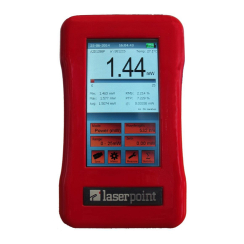
Figure 1 shows an image of Plus 2 meter touch screen display; the upper part of the display
reports the measurement information and the lower part is filled with touch buttons for
measurement settings. Each part of the display has horizontal sections showing specific
information as described below:
Figure 1
The touch screen display
a) Date - Time - Battery/network icons
b) Sensor Head model, serial number and operating
temperature (°C)
c) 4 digits numerical display and measurement
function units
d) Analog bar graph normalized to the selected full
scale
e) Sample counts and time considered for the statistical
elaboration, if selected. Also warnings and
alarms/alert messages are displayed in this section.
f) Duration of the data logging and specific
measurement settings
g) Four self-explanatory function buttons: Mode,
Wavelength, Range and Zero .
h) Four function buttons: Save, Menu, Measure and
Statistics offer quick access to specific sub-menu
interactive windows.
a
b
c
d
e
f
g
h

Laserpoint s.r.l. -Plus 2 - Quick Start Guide - All Rights Reserved 3
2.2.
C
ONNECTING A SENSOR HEAD TO
P
LUS
2
M
ETER
Insert the sensor head IIS Connector
(Intelligent Identification System) into
the socket marked "Head Input" on
Plus 2 top side (Figure 2).
Figure 2
Top Side View
2.3.
S
WITCHING
P
LUS
2
M
ETER
ON
/
OFF:
To switch Plus 2 Meter on keep the white on-off button on the instrument top side (Figure 2)
pressed until the screen lights on as shown in Figure 1.
Note: If the instrument is powered by its battery the sensor head has to be plugged in before switching
the unit on to avoid the "NO HEAD" blinking notice appearing on the display and the consequent
display switch off occurring in few seconds.
To turn Plus 2 off press the on-off button for few seconds until the display goes off. The current
Plus 2 settings are automatically saved before the instrument switches off.
2.4.
S
ETTING A LASER WAVELENGTH
:
a) Touch the Wavelength screen button
g) in Figure 1 to open the “edit lambda”
window (Figure 3).
b) Select a wavelength from the list
shown at the left hand side of the window or
touch an “edit nm” button to input a specific
wavelength not shown in the list.
c) A keyboard pops up (Figure 4) allowing
the wavelength selection. The selected
wavelength value must fall in the range
shown at the top of the wavelength menu.
Figure 3 Figure 4
Note: The available wavelengths and editable wavelength range depend on the Sensor head
characteristics and calibration. There is no choice but the list for wavelengths beyond 2100nm.

Laserpoint s.r.l. -Plus 2 - Quick Start Guide - All Rights Reserved 4
2.5.
M
ANUAL OR AUTOMATIC POWER RANGING SELECTION
:
The measurement full scale or range can be adjusted according to user’s needs. The selection can be done
by touching the “Range”screen button and scrolling to choose the range option.
Select the appropriate range manually, or choose the “Auto” mode to let Plus 2
meter managing the measurement range automatically.
2.6.
O
FFSET FUNCTION
:
In certain cases it is useful to introduce an offset level in a measurement. To activate this function
touch the “Zero” screen button and the presently measured power value is
acquired as offset level. When the "Offset" function is activated, the offset value/units appear in
the “Zero” screen button and an additional yellow spot is shown at the upper right corner of the
“Zero” screen button . To cancel the offset, press the "Zero" button again.
2.7.
Z
ERO
S
ETTINGS
All meter adjustments, including ADC zeroing, are carried out by Plus 2 firmware. However
Laserpoint recommend to reset Plus 2 Meter every time a new sensor head is being plugged in
following the instructions given below:
a) Press for more the Zero button until
the window shown in Figure 5 appears in the
display segment e) as shown in Figure 1.
Note: While zeroing make sure the instrument is not affected
by electrical noise and the sensor is blind to light.
b) Press “Yes” and wait few seconds whilel the display
shows the notice “Wait for zeroing”. When the ADC
has been reset the notice “Zeroing Completed” is
finally displayed (Figure 6) and the meter is ready
again to be used.
Figure 5
Figure 6

Laserpoint s.r.l. -Plus 2 - Quick Start Guide - All Rights Reserved 5
2.8.
S
ELECTING
P
OWER OR
E
NERGY MEASUREMENT
:
Touch the “Mode”screen button to switch from Power measurement mode to
Energy measurement mode ; shown measurement units are according to sensor
head type and expected range to be used.
If upon switching from Power mode to Energy mode,
Plus 2 displays the message: "Zeroing is necessary"
(Figure 7), press OK and follow the instructions
already described in “Zero adjustment” section.
Figure 7
Note: The energy mode allows the manual range setting only, hence the selection of a proper energy
range has to be done by pressing the "Range" screen button and operating as described in 2.5.
2.9.
S
INGLE PULSE OR BURST ENERGY MEASUREMENTS
:
Set the Energy Mode as described above.
The green spot at the right-hand side of the measured value indicates
that Plus 2 meter is ready to measure an energy pulse (Figure 8).
During the laser pulse, the upper part of the display shows the notice
“Acquisition”, but shows no figures and the green spot turns red
(Figure 9).
The “Acquisition” time usually ranges from 1 to 5 seconds depending
on the used sensor head and if a single pulse or multiple pulses are
acquired.
When a pulse/burst energy acquisition is completed, the measured
energy will be displayed as shown in Figure 10 and the spot at the
right hand side of the measured value re-converts its colour back to
green indicating that Plus 2 is ready for a new pulse measurement.
Figure 8
To correctly measure the integral energy
of a burst of 2 or more pulses by a
thermopile head ensure that the pulse
frequency is > 1Hz to avoid detecting
single pulse energies
Figure 9 and 10

Laserpoint s.r.l. -Plus 2 - Quick Start Guide - All Rights Reserved 6
2.10.
S
ETTING THE ENERGY THRESHOLD
To avoid unwanted contribution of thermal noise or background
radiation to the measured pulse energy, the instrument has been
designed not to respond to pulses below a preset energy threshold.
Hence an Energy Threshold has to be set and to do so follow the
instructions below:
a) Ensure the instrument is in Energy Mode, touch the screen
button to open the Measure Settings window.
b) Touch the Start threshold box and scroll to select the
threshold among three options: “high”, ”med” or “low” .
Figure 11
Hints to select an Energy Threshold value: The factory setting of energy threshold of the instrument is
"med”, i.e medium. If noise is high enough to trigger the meter, set the threshold to "high."
If the expected pulse energy is low and triggering the meter might be critical, set the threshold to
"low."
2.11.
M
EASURING
I
RRADIANCE AND
F
LUENCE
a) Touch the button “Measure” to open “Measure
Settings”. Select the Shape of your beam and input the
requested dimensions (Radius for a circular shape, Width and
Height for rectangular shape), then close the menu.
b) Next measures in Power mode will be displayed as Irradiance
(unit of measure: W/cm2), while in Energy mode they’ll be
displayed as Fluence (unit of measure: J/cm2).
c) To de-activate Irradiance/Fluence mode, select ”none” for
shape in “Measure Settings” window.
Figure 12

Laserpoint s.r.l. -Plus 2 - Quick Start Guide - All Rights Reserved 7
2.12.
M
EASUREMENT STATISTICAL ELABORATION SETTING
a) Touch the Statistics screen button on Plus 2 display to
make Statistics window appear (Figure 13).
b) Select one of the Four processing options are available:
Off: no statistics.
Continuous: the data elaboration is carried out on a
continuous data collection basis.
Repeated: the data are repeatedly collected and elaborated
within a user’s defined time period.
Single: the data are collected and elaborated only once
within a user’s defined time period.
c) Press the “Reset”button to confirm the selection.
Figure 13
2.13.
D
ATA LOGGING TO A
USB
MEMORY STICK
a) Insert the USB memory key into the dedicated port on
Plus 2 left side.
b) Touch the "Save…" screen button to open the
Data Logging window.
Figure 14
c) Select the desired data to be saved: values, statistics or both.
d) Select a Sample Rate value between 0.5 s and 99 s.
Note: The sample rate value refers to Values and Statistics data when
Continuous statistics is selected or to Values data only when Single or
Repeated statistics are selected, as in these cases Statistics data are
saved each time they are refreshed.
Figure 15
e) Select the acquisition mode:
-Manual acquisition: check this box to start and stop the acquisition manually.
-Timed acquisition: de-select the “Manual acquisition” box and input the desired time
acquisition value to define when the data acquisition has to be stopped.

Laserpoint s.r.l. -Plus 2 - Quick Start Guide - All Rights Reserved 8
f) Exit the Data Logging page by clicking on the “OK” button.
Note: Depending on the USB flash memory speed, the USB drive might not
be ready yet and in this case the ”USB not ready” notice is displayed.
Wait few seconds until this notice disappears.
g) The “Save..” button converts now in a green character
“START”button.
Touch to begin the data logging.
h) During data logging a timer shows the elapsed time if the
selected acquisition mode is Manual or the time left if the
selected acquisition mode is Timed.
During data logging the “START” button converts now in a
yellow character “STOP” button.
Touch to stop the data logging.
Figure 16 and 17
Note: Data are saved in the USB memory folder X:\PLUS2\”head serial number”\
Values and statistics are saved in separate files named as follows:
“DATA_nnn.txt” for values
“STAT_nnn.txt” for statistics
2.14.
T
HE
“M
ENU
”
B
UTTON
a) Touch the “Menu”button to open the Menu window.
b) The first two lines Date and Time settings are self-explicative.
Language and Display Colour choices (not yet available).
For energy saving purpose, when Plus 2 is powered by battery,
both the screen and the whole instrument turn off after a certain
period of time of instrument inactivity; these two off times can be
controlled via “Menu” interactive window.
c) Display off: after a certain time of Plus 2 inactivity the display
turns off showing a stand-by notice only. Selecting ON/OFF
activate/deactivate this feature; if ON has been selected,
Display off time can be set from 1 to 30 minutes. Touching the
screen when Plus2 is in stand-by mode recovers immediately
the instrument display operation.
Figure 18

Laserpoint s.r.l. -Plus 2 - Quick Start Guide - All Rights Reserved 9
d) Auto off: after a certain time of inactivity Plus 2 turns off. Selecting ON/OFF
activate/deactivate this feature; if ON has been selected, Auto off time can be set from 1
to 600 minutes.
Note both “Auto off” and “Display off” features are active only when Plus 2 is powered by its
battery. When Plus 2 is plugged in a power line both the instrument and its display will remain
on regardless to Auto off and Display off set values.
e) Factory restore: this function resets measurement, statistics and wavelength settings to
the ex- factory conditions losing the information pertaining to all sensor heads that have
been connected to Plus 2 meter.
f) 90° Full Screen: this option switches the screen to a 90° turned full screen high visibility /
high contrast display (Figure 19) showing only the measurement value and related units.
Click the “X” screen button to return to the main screen configuration.
Figure 19

Laserpoint s.r.l. -Plus 2 - Quick Start Guide - All Rights Reserved 10
3.
P
LUS
2
S
PECIFICATIONS
:
Detector Compatibility
Laserpoint Thermopile, Photodiode and OEM heads
Input ranges
7 mV –700mV full scale, in
9 ranges
A to D Sampling rate
64 Hz
A to D resolution
23 bit ADC resolution, 16bit processing resolution
Electrical accuracy
± 0.5%
Electrical input noise level
500nV
Input Offset Voltage drift (typical): -4nV/°C
Dynamic range
8 decades
Analog output
0.025 - 2 Volt, with 16-bit (0.0015% resolution.)
Analog output accuracy
±0.1% ±2mV relative to display
Dimensions
170Hx100Wx36-50D (mm)
Weight
380 g
Display
4.3" TFT LCD high brightness, 480 x 272 resolution,
resistive touch panel (96H x 55W mm).
Display digit height
15mm -25mm Full Screen
Bargraph segments
250 pixel width
Battery
Built in rechargeable Li-Pol. 3.7V 3700mAh
Battery charge time
7-8 hours if not working
15-20 hours if working
Battery run time
> 9 hours in normal operation
> 15 hours in stand-by display mode
Supplied Battery Charger
Input 100/240Vac 50/60Hz Out 5Vdc 1A,
Charging current is 0.5A (Plus 2 may be charged
through a PC USB port).
Other manuals for Plus 2
1
Table of contents
Other LaserPoint Measuring Instrument manuals