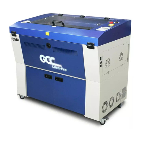
LaserPro T500 User manual

i Important Safety Information
Maintenance Manual
T500

ii
Contents
Contents ................................................................................... ii
Introduction ............................................................................. 1
Component Overview ............................................................. 3
Motion System Assembly ............................................................................................ 3
Lens Carriage Assembly .............................................................................................. 5
X Motor Unit Assembly ............................................................................................... 6
Y Motor Unit Assembly ............................................................................................... 7
Laser System Assembly ............................................................................................... 8
Controller and the Laser ...................................................................................... 8
Laser Controller .................................................................................................. 8
P M (Clock) Frequency .................................................................................... 9
Laser Tube .......................................................................................................... 9
Power System ............................................................................................................ 10
Power Supply ............................................................................................................. 12
Top cover and Front door........................................................................................... 13
Maintenance .......................................................................... 14
X-Y Motion System ................................................................................................... 14
The Rails and the Bearing’s Surfaces................................................................ 14
The X and Y Motor Removal and Belt Tension Adjustment............................. 15
Control Panel Removal .............................................................................................. 16
Dismount Laser Tube ................................................................................................. 16
Optical Alignment ...................................................................................................... 18
Optical Alignment Tool .................................................................................... 18
Beam Expander module .................................................................................... 19
Laser Diode (Red Beam Source)....................................................................... 19
Optical Adjustment ........................................................................................... 19
Laser Diode and Mirror Adjustment ................................................................. 20
Mirror 1 Adjustment ......................................................................................... 21
Mirror 2 Adjustment ......................................................................................... 21
Mirror 3 Adjustment ......................................................................................... 22
Mirror 4 adjustment .......................................................................................... 22
Hidden Diagnostic Procedures ............................................ 23
System Diagnostics .................................................................................................... 23
The Build-in Hidden Diagnostic Functions ...................................................... 23
Troub eshooting .................................................................... 25
Initializing Issue......................................................................................................... 25
Before turn on machine, please check the position of lens carriage. If the bottom of
lens carriage is too low, it may hit the edge of working table or cutting bar and crash
machine. Sometime, carriage badly, the x- y axis will be twisted a little and affect
engraving/cutting quality. .......................................................................................... 25
Laser Related Problems ............................................................................................. 25
No Laser Output ................................................................................................ 25
The Laser Stop firing During a Cutting/Engraving Job .................................... 25
eak Laser Output ............................................................................................ 26
System Related Problems .......................................................................................... 26
The System Fails During Initialization ............................................................. 26

iii Contents
“X-motor Error” Message ................................................................................. 26
“Y-motor Error” Message ................................................................................. 26
Error message on X/Y motor drivers ................................................................ 27
“Graphic as Clipped…” Message .................................................................. 36
“Command Error, Use GCC driver or HP Pen Plotter Command” Message .... 36
Mechanical Related Problem ..................................................................................... 36
eak Laser Beam at the Right Side of the orktable ...................................... 36
Poor Output Quality .................................................................................................. 37
iggling Vertical Engraved Line...................................................................... 37
avy Vector Cutting Line................................................................................. 37
Miscellaneous Problems ............................................................................................ 37
Blurry Red Beam or Failed Red Pointer ........................................................... 37
Image Breaks and Shifts ................................................................................... 37
Image Distorted or Drifts toward One Direction .............................................. 37
Smoke Can Not Be Vented Properly ................................................................. 37
Output Is Not Precise ........................................................................................ 37
E ectronic and Mechanica Diagrams/Part ist ..................... 38


1 Introduction
1
Introduction
This maintenance manual provides a component overview for the LaserPro T500 and
instructions for replacing and maintaining the components of the machine. It also
includes a troubleshooting chapter with some handy hints when problems arise or if the
machine does not operate properly.


3 Component Overview
2
Component Overview
The following diagrams represent all of the maintainable mechanical and electronic
components of the machine, and their parts lists for convenient parts replacement.
The LaserPro T500 includes six main units as follows. Each unit will be discussed in depth
in later chapters.
X-Y Motion System
Lens Carriage
X Motor Unit Assembly
Y Motor Unit Assembly
Laser System Assembly
Power Supply
Top cover and Front door
Motion System Assembly

4
The Motion System is driven by servomotors, which includes X and Y motors. The X motor sits at
the right hand side of the X-rail, and moves the lens carriage left and right via the X-axis belt, while
the Y motor moves the X-rail in a forward and backward motion simultaneously using two Y-axis
belts at either end.
The motion system provides an exact positioning and coordination guiding the laser beam to
engrave the material at the designated target location on the work piece. The laser beam comes
from the laser tube, and is reflected by adjustable mirrors to pass through a focal lens that focuses
the energy.
There are three reflective mirrors within the motion system. Mirror 2 is situated at the top left
corner of the motion frame, and receives and reflects the laser beam to mirror 3 that sits on the left
side of the X-rail. After passing through Mirror 3, the laser is reflected to mirror 4, which is fixed
above the focal lens of the lens carriage. Once reflected through Mirror 4, the beam is focused
through the focal lens onto the work piece.

5 Component Overview
Lens Carriage Assembly
The lens carriage consists of a mirror (Mirror 4) and lens. Mirror 4 reflects the beam through the
focal lens that focuses the beam onto the material. In general, a 4.0-inch lens is included as standard
with the machine. However, there is also a 2.0-inch lens available.
For the detail components and parts numbers of lens carriage, please see the Mechanical Diagram
section.
For
4
”
lens
For 2
”
lens
Draft Pipe
P/N: 22801913G
Air pipe
P/N: 23300069G

6
X Motor Unit Assembly
The X-motor unit is located at the right side of the machine. X motor PCB has two sensors that can
sense the x and y margin when the lens carriage moves toward it. hen the lens carriage’s detector
detects the sensor, the lens carriage will then move in a diagonal direction to the original point
(back left corner of the machine).
X motor PCB P/N: 290090960G X axis right block. For detail
assembly diagram and part
numbers, Mechanical Diagram
section.
AC servo motor
P/N: 23100062G

7 Component Overview
Y Motor Unit Assembly
The Y-motor unit is located at the back of the machine. Y motor and X motor are the same servomotor, parts
number (P/N) is 23100062G.
AC servo motor
P/N: 23100062G
Y axis pulley and belt. For detail
assembly diagram and part
numbers, Mechanical Diagram
section.

8
Laser System Assembly
Laser operation occurs when a medium (in LaserPro T500’s case is C
O
2) is excited within a chamber. The
laser tube is a sealed metal tube. This light is amplified from bouncing forth and backwards inside the high
voltage medium. A small hole on the one end’s mirror allows the amplified and coherent light to escape or
shoot out, and is reflected by Mirror 1 toward Mirror 2 (See Motion System on page 13 for the continuing
path of the laser beam). The C
O2
laser output has a wavelength of 10.6µm that is invisible to human eyes.
The red beam is used as an aid to show the approximate location C
O2
laser beam path.
The “Laser” has found itself as a crucial component in many emerging applications. Some of frequent-used
applications today are engraving, cutting, marking and even 3D prototyping.
Contro er and the Laser
One of the major functions of the main board is to control the laser firing at a right moment on the right spot.
The Synrad’s C
O2
laser has a maximum firing pulse rate of 25KHz. In order to keep a prompt response in
such short duration of time and achieve a perfect synchronization of time and space, a firing signal is
constantly sent out from the main board’s laser control, CON2, to the Synrad laser. Because there is 30
DCV available to trigger the laser, the laser tube is constantly in stand-by mode and ready to fire
immediately upon a call. However this manual will focus on the I/O between laser controller and laser tube.
The detail operating theory of the laser tube can be obtained from Synrad, the laser tube’s manufacturer.
Laser Contro er
The laser controller is built-in on the motherboard. For raster mode, it synchronizes the encoder signal for
firing in raster mode. As for vector mode, it is control by the firmware inside. In addition to the complex
algorithms inside the firmware, there are some others factors that may affect the performance of laser tube.
F201 (200w) tube does
not need fans. The RF
and tube combine
together as one.
Ti 100P is
water cool
laser tube.

9 Component Overview
In the following section, we will describe the Tickle Pulse and P M Frequency, which have an important
role in laser control.
PWM (C ock) Frequency
P M duty cycle controls the laser’s power level so you can direct the laser to perform a variety of cutting
and marking tasks. The standard frequency is 5 KHz, which has a period of 200µs. The duty cycle of a
P M waveform is the percentage of the period that the output signal is high. Please refer to the glossary in
this manual for more detailed information.
Laser Tube
The Synrad laser is a sealed cavity, high frequency, RF excited, diffusion cooled CO2 laser, designed for
industrial use as a cutting, welding or marking tool.
The principles of operation of the laser are as follows. A laser discharge (active zone) is established
between the wave guiding electrodes by a radio frequency voltage. The rear mirror and output mirror form
the optical resonator. The laser beam is produced within the resonator, and is emitted through a window.
ater is used to cool the electrodes.
The following are the technical specifications for the S nrad Ti series and F series tubes and Rofin
SR 150w.
Input/Output Specifications: Ti-60 Ti-80 Ti-100 Rofin 150SR F200
avelength………….10.57-10.63µm. 10.57-10.63µm. 10.57-10.63µm. 10.6µm….. 10.2-10.7µm
Output Power (Continuous)……60 ………..80 ……..100 …… …150 …… …200
Power Stability…………………±7%…………±7%..............±7%......... ±7%.......... .....±10%
Input Voltage…………………48V dc………48V dc ……48V dc…… 50V dc.....…96V dc ±2V dc
Input Maximum Current………18A………..…22A……….. 35A………45A ... ... .....…36A

10
Power System

11 Component Overview
60A Terminal,
P/N: 21100303
30A Breaker,
P/N: 25700049
20A EMI Filter,
P/N: 21800026G
25A/6P Terminal,
P/N: 21100311G
150w/12v Power Suppl ,
P/N: 24500037
Laser Signal PCB,
P/N: 29004101
DC 12V PCB,
P/N: 29005059G
Power suppl
HRP-150-40G,
P/N: 245000990G
25A/3P Terminal,
P/N: 21100236G
20A Circuit Breaker,
P/N: 22300008G
Y motor PCB,
P/N:
29002510G
X/Y motor driver,
P/N: 220004880G

1
Power Supply
The power for the motion system uses both +48v DC for driving servo motors and +5v DC for circuit board
such as Main board. Inside the Main Board, there is a built-in mechanism to protect the system from an
over-current.
Power Supply for LED light and Fans (150w, 15v dc), P/N: 24500037
Power Supply for Firestar Ti60, Ti80 laser tube (1000w, 48v dc), P/N: 24500064G (Ti60*1, Ti80*1)
Power Supply for Firestar Ti100 laser tube (2400w, 48v dc), P/N: 245001050G (Ti60*1, T100*2)
Power Supply for Rofin 150SR laser tube (2400w, 48v dc), P/N: 245001050G (tune voltage from 48v to
50v dc_ Rofin 150SR needs 50v dc)
Power Supply for Firestar F201 laser tube (2400w*2, 48v dc), P/N: 245001050G (serial connection_F201
needs 96v dc)
The AC input power for the T500 system ranges from 220Vac to 240Vac. In some countries, to extend the
maximum protection against commercial power failure, as well as voltage fluctuations, a power conditioner
that provides line regulation and noise filtering is recommende
5272 main board, P/N: 290093740G( red
and green board together)
2400w/48v dc
Power Suppl ,
P/N:
2
45001050G

13 Component Overview
Top cover and Front door
P/N: 25 00050
Power Switch
P/N:
290089940G
Control panel
P/N:
244048 90G
Top Cover
P/N:25 00095G
Emergency SW
P/N: 25 00032
LED Lamp SW
P/N: 22802801G
Window of Front
Cover
P/N: 22802800G
Acrylic Window
P/N: 24450940G
Drawer
P/N: 2330038 G
Drawer handle
P/N:25 00094G
Key Switch
P/N: 244048800G
Front Cover
P/N: 26500165G
Handle
P/N: 26500166G
Window hinge
For detail diagram and part numbers, see Mechanical Diagram
section.

14
3
Maintenance
This chapter gives a detailed explanation of how to maintain the maintainable mechanical
and electronic components of the machine that includes the cleaning, replacement and
adjustment of these components.
To remove, maintain or tune any part or component, please turn off machine
power first.
X Y Motion System
The Rai s and the Bearing’s Surfaces
The basic but very important maintenance of the motion system is a regular cleaning of the
rails and bearing’s surface. The surfaces of the rails, especially the X-axis rail, accumulate
dust and debris very easily after some engraving jobs. If the dust and debris are not
removed, the bearing on the lens carriage will roll with a bumpy effect. This bumpy effect
is critical for laser. Any slight jar or vibration will diverge the beam path and affect the
overall output quality.
The cleaning job can be carried out with a piece of dry and clean rug. ipe the surface of
the X-axis rail with a dry rug. To clean the bearing, shift the Lens Carriage and then use
the dry rug. In general, weekly cleansing is recommended. If you engrave or cut wood,
glass or other debris-prone materials in a heavy-duty manner, a daily cleaning is necessary
for retaining the output quality.
Do not lubricate the rails and bearings, as grease will attract more dust and dirt to their
surfaces.
X-axis
Rail
Y-axis
Rail

15 Maintenance
The X and Y Motor Remova and Be t Tension Adjustment
To adjust the belt tension of the X and Y motors, their covers need to be removed.
To remove the cover of the X motor and then the X motor:
1. First remove the two screws located either side of the X motor.
. Next loosen the locking screw located on the top of the X motor housing.
NOTE: The locking screw must be loose to adjust the belt tension, once adjusted the
locking screw must be tightened again.
3. Remove the four screws on the front of the X motor housing.
4. Remove the cover from the X motor housing, and then take the motor out.
To remove the cover of the Y motor, and then the Y motor:
1. First remove the screws on top and beneath the Y motor housing.
. Next remove the screw on the right side of the Y motor housing.
3. Then remove the two screws to the right side and the two screws to the left side of
the Y motor housing.
4. And then, remove the four screws on the front of the Y motor housing.
NOTE: Once the screws have been removed from the bracket, the belt will be loose, and
so be adjustable.
5. Then, take off the cover and protective plate.
6. Finally, take the Y motor out of the housing.

16
Control Panel Removal
To remove the control panel from the machine, unplug control panel cable first, then loose four screws on
the back of control panel. Then the back cover can be removed. Then there are four screws for control panel
PCB. Then remove these four screws, the whole control panel can be removed.
Dismount Laser Tube
The laser tube is a precise and delicate device that is located on the bottom back side of the machine. If it
needs to be removed for service purpose, please handle it with extra care.
In general, the laser tube does not require displacement for general maintenance, but if you find laser power
either lost significantly or not outputting at all, and are also sure all optics devices (mirrors and lens),
including the beam expander, are clean and in good condition, the laser tube will need to be removed for
repair.
NOTE: For a more complete explanation of lens cleaning, please refer to the T500 User’s Manual.
To remove Synrad Firestar F 201 (200w) laser tube, the beam expander module needs to be dismounted.
Then, disconnect signal cable and water pipes. Then dismount three screws from the bottom bracket. hen
sending laser tube back for repair, only send the laser tube, please do NOT send back the beam expander
module or signal cable.
Table of contents
Other LaserPro Engraver manuals