LaserTrack Flare User manual

INSTALLATION MANUAL
LASERTRACK FLARE

2
CONTENT
In the box ........................................................................................................ 2
Important information ...................................................................................... 3
Location of the transponder(s).......................................................................... 4
Installation of the transponder(s) ...................................................................... 5
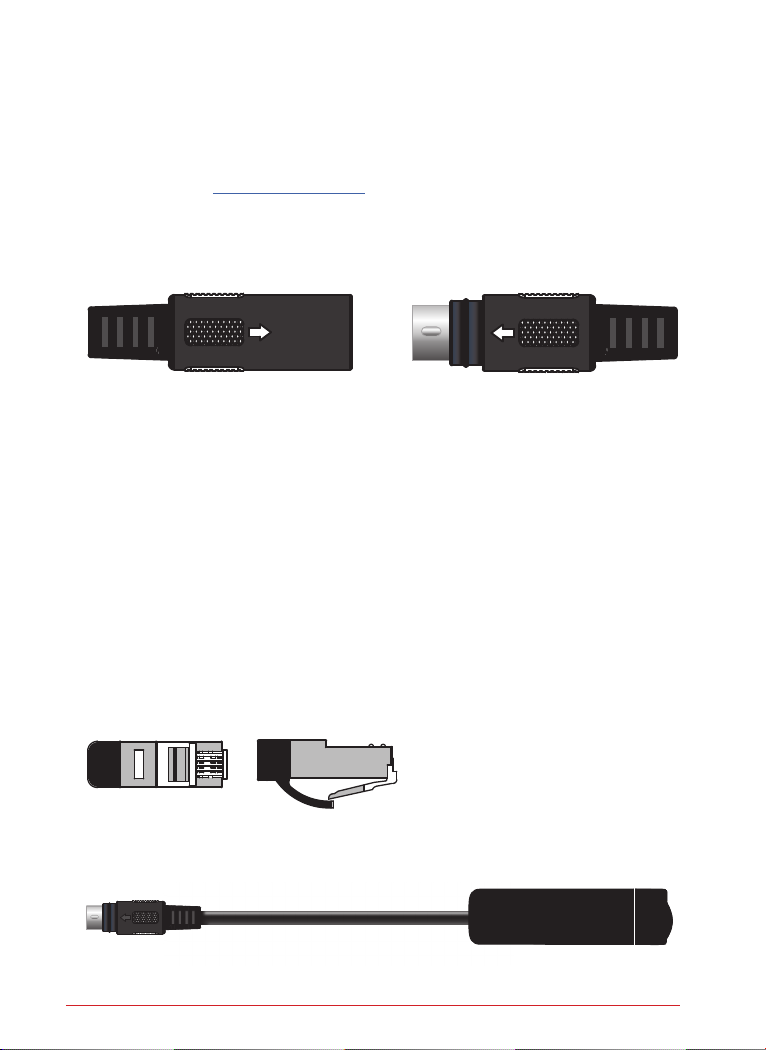
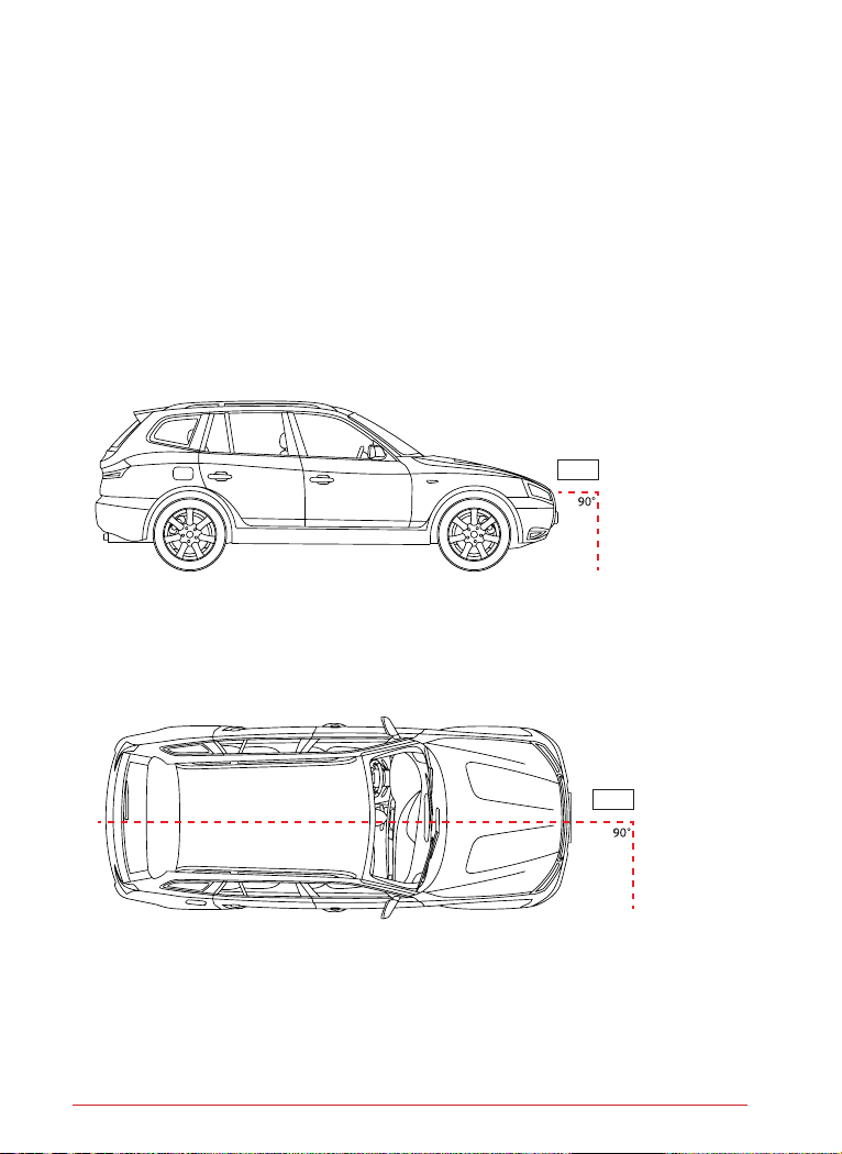
Alignment of the transponder(s) ....................................................................... 5
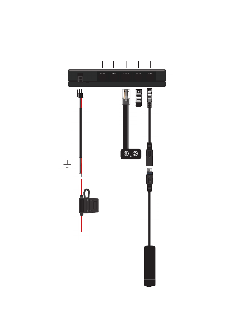
Connecting a LaserTrack Flare with 1 front transponder..................................... 6
Connecting a LaserTrack Flare with 2 front transponders................................... 7
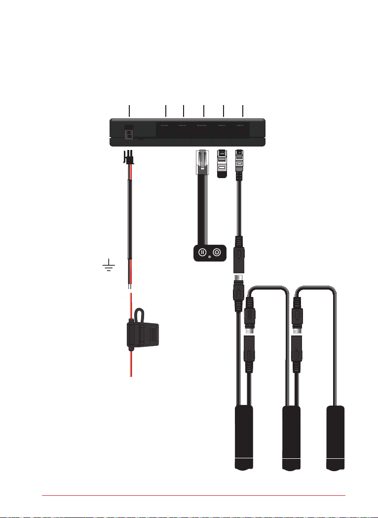
Connecting a LaserTrack Flare with 3 front transponders................................... 8
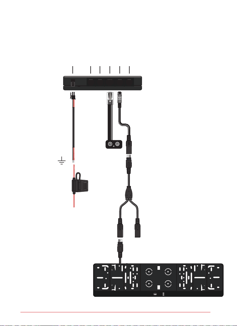
Connecting a LaserTrack Flare with 1 rear transponder...................................... 9
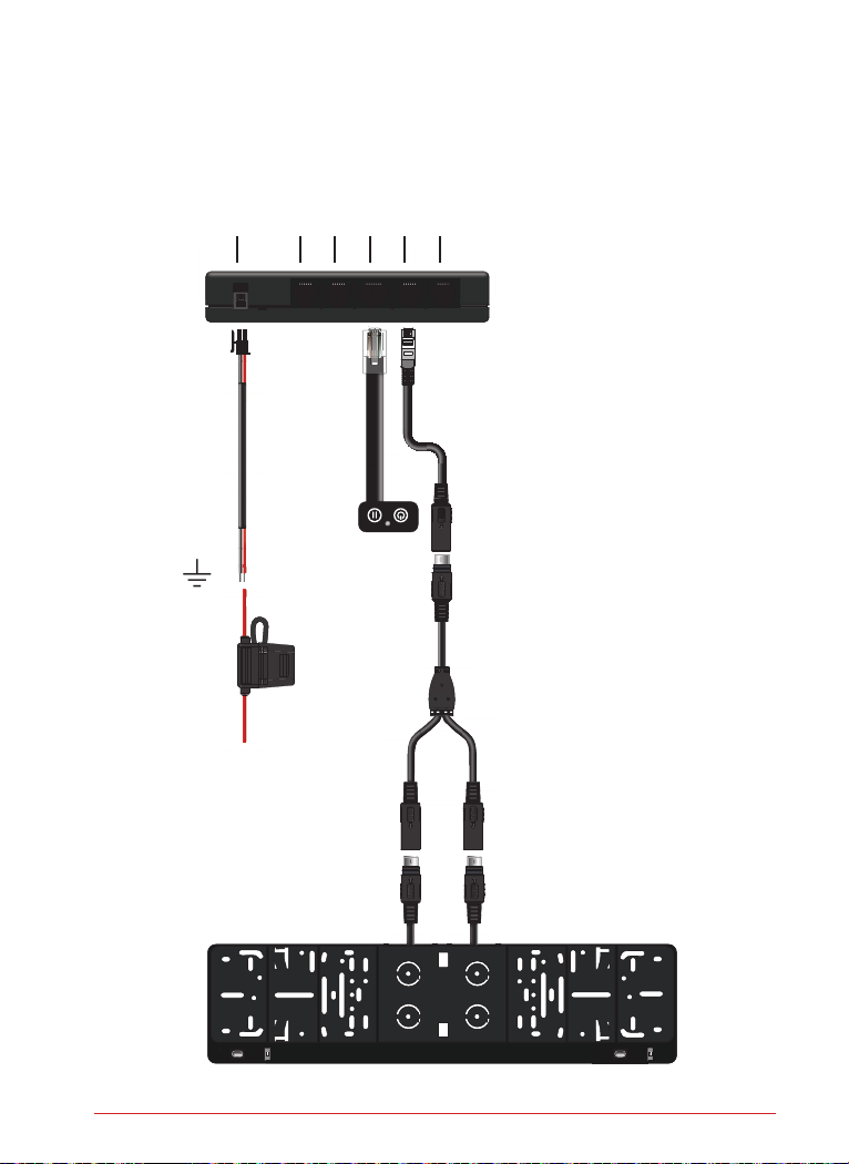
Connecting a LaserTrack Flare with 2 rear transponders .................................. 10
Technical specifications................................................................................... 11
IN THE BOX
Laser Remote Control Base System
• Main unit
• Transponder (single wire)
• Information display
• Transponder extension cable (5 meters)
• Power cable
• Fuse holder including fuse
• Mini bubble level for alignment of the transponder
• SD card
Laser Remote Control Transponder (for front or rear extension)
• Transponder (single or dual wire)
Laser Remote Control license plate frame for front and / or rear moun-
ting (available soon)
• License plate frame with one or two pre-installed transponders.

3
IMPORTANT INFORMATION
Install LaserTrack Flare in your vehicle first and make sure the transponders are
installed according to the instructions. After that, register and configure the system
on the web page www.laser-track.com under 'My LaserTrack'.
The plugs of the transponders are equipped with arrows. Make sure both arrows
are facing each other before pressing the plugs together.
To ensure a waterproof connection under the most extreme conditions, the plugs
are fitted with o-rings. Check the o-ring for presence and damage before pressing
the plugs together.
LaserTrack Flare uses a bus system for internal communication. In addition to the
advantage of faster communication between the transponders, this has the additio-
nal advantage that per transponder group (front or rear) you need to draw only one
cable through the vehicle's fire wall.This will not only make the Installation simpler
but also a lot more efficient.
Attention!
In a bus system it is important that a termination is placed at the end of each bus
connection that is not in use. A terminator is factory-installed in the connector for
the rear-transponder(s) of the main unit. Only remove the terminator when con-
necting one or more rear transponders.
There is also a terminator fitted in the single wire transponder. Hence, this should
always be the last transponder in a series.

4
LOCATION OF THE TRANSPONDER(S)
With one front transponder; In the centre of the vehicle, preferably above the
license plate.
With two front transponders; Equally divided between the two headlights and
the license plate.
With three front transponders; Equally divided between the two headlights
and the license plate.

5
INSTALLATION OF THE TRANSPONDER(S)
Due to the extremely compact dimensions of the LaserTrack Flare transponders,
no mounting brackets are included. It is recommended to bond the transponders
into grille or ventilation apertures with a two-component kit or glue (for example:
Würth Replast Easy plastic glue or Innotec Topfix).
ALIGNMENT OF THE TRANSPONDER(S)
1. Park the vehicle on a flat (level) surface and ensure proper (high/low) align-
ment of the transponder(s). Use the supplied bubble level for this purpose.
2. Ensure proper horizontal (left/right) alignment of the transponder(s). Draw an
imaginary line from the car's longitudinal axis and ensure that the transpon-
der is parallel to it.

6
DIAGRAM OF LASERTRACK FLARE WITH 1 FRONT TRANSPONDER
POWER 12V.
FRONT
TRANSPONDER(S)
REAR
TRANSPONDER(S)
USER
INTERFACE
SYSTEM
INTERFACE 1
SYSTEM
INTERFACE 2
Black (Gnd.
Red; Via ignition
key-switch (+15)

7
DIAGRAM OF LASERTRACK FLARE WITH 2 FRONT TRANSPONDERS
POWER 12V.
FRONT
TRANSPONDER(S)
REAR
TRANSPONDER(S)
USER
INTERFACE
SYSTEM
INTERFACE 1
SYSTEM
INTERFACE 2
Black (Gnd.
Red; Via ignition
key-switch (+15)

8
DIAGRAM OF LASERTRACK FLARE WITH 3 FRONT TRANSPONDERS
POWER 12V.
FRONT
TRANSPONDER(S)
REAR
TRANSPONDER(S)
USER
INTERFACE
SYSTEM
INTERFACE 1
SYSTEM
INTERFACE 2
Black (Gnd.)
Red; Via ignition
key-switch (+15)

9
DIAGRAM OF LASERTRACK FLARE WITH 1 REAR TRANSPONDER
POWER 12V.
FRONT
TRANSPONDER(S)
REAR
TRANSPONDER(S)
USER
INTERFACE
SYSTEM
INTERFACE 1
SYSTEM
INTERFACE 2
Black (Gnd.)
Red; Via ignition
key-switch (+15)

10
DIAGRAM OF LASERTRACK FLARE WITH 2 REAR TRANSPONDERS
POWER 12V.
FRONT
TRANSPONDER(S)
REAR
TRANSPONDER(S)
USER
INTERFACE
SYSTEM
INTERFACE 1
SYSTEM
INTERFACE 2
Black (Gnd.)
Red; Via ignition
key-switch (+15)

11
TECHNICAL SPECIFICATIONS
• Power supply: 10 – 16V
• Power consumption at 12V. when idle
Main unit: 60mA
Transponder: 70mA
• Power consumption when active
Main unit: 60mA
Transponder: 140mA
• Fuse: 5A
• Temperature range: -20°C - +70°C
• Dimensions in mm.
Main unit: 124 x 65 x 22 (L x W x H)
Transponder: 15 x 18 x 65 (L x W x H)
Display: 36 x 19 x 5 (L x W x H)

Zuidergracht 21 | 3763 LS Soest | the Netherlands | info@tracktechnologies.nl | +31 (0)35 760 5760
www.laser-track.com
Table of contents