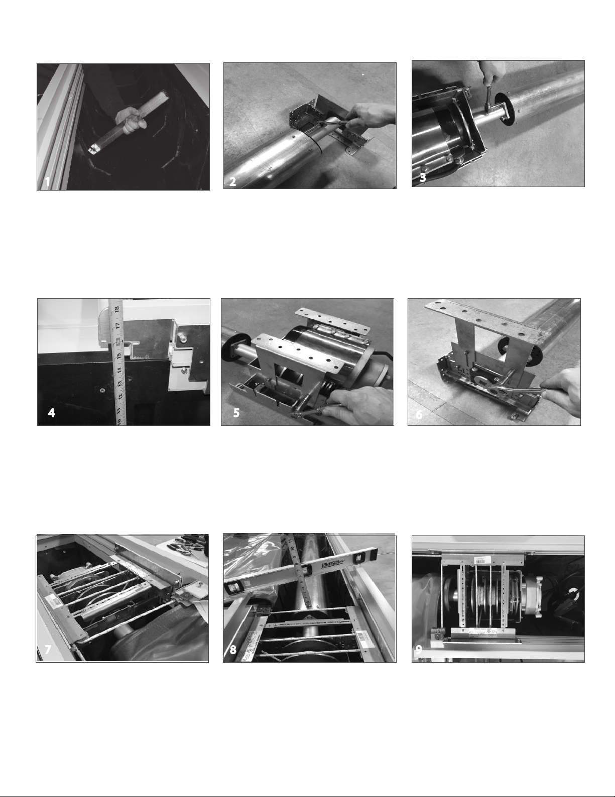
Step By Step Instructions
With the motor end positioned upside
down, install the mounting feet using the
nuts (34) provided.
Positioning the Mechanism Lower
the assembled mechanism with attached
roll-up tube into the cover box and place it
roughly in the position it will anchored.
Note: If the cover box isn’t square to the
pool, position the mechanism in the cover
box so it will be square to the cover track.
12
56
7
Adjusting Mechanism Height
Measure from the bottom of the housing to the
top of the track. The top of the mechanism should
be installed so it is at the same height as the top of
the track. Because the top of the mechanism is
adjustable, use the feet to position the roll up tube
as high as possible in the cover box, but allowing
clearance so the cover won’t rub on the lid
brackets.
Connecting the Roll-up tube
With the non-motor end turned upside
down, attach the cone for the non-motor end
to the roll-up tube using the 3/8” x 1-1/4”
bolts (39) and lock washers (40) provided.
With the motor end turned upside down,
attach the cone to the motor end of the
mechanism using the 3/8” x 1-1/4” bolts
(39) and lock washers (40) provided.
Tighten these bolts with a 9/16” wrench.
Cover Box Preparation
Use a garden hose to clean out the cover
box. During this process, make sure the
water is draining from the cover box. It is
critical that all cover boxes have adequate
drainage. Inadequate drainage may void the
mechanism warranty. If there is no drain or
inadequate drainage in the cover box,
contact your Coverstar Representative.
3
4
Numbers in parenthesis refer to parts shown on page 3.
Install the mounting feet on the non-motor
end using the nuts (34) provided. The top of
the pulley bracket on the non-motor end
should be flush with the top of the track.
With the mechanism and tube assembled
and set in place in the housing, check the
roll-up tube for level. This is crucial to proper
operation of the cover. Position a level
across the housing. Measure from the roll-up
tube to the bottom of the level on both the
motor end and non-motor end of the
mechanism. Adjust height of the non-motor
end feet if needed to level the roll-up tube.
8
Position the mechanism in the cover box so
that the roll-up tube is centered in the
cover box front to back and properly
aligned with the track. The rope should
travel straight from the track to the pulley.
9
© Latham Pool Products, Inc. 2019. All rights reserved.