Latronics DC-1230 User manual

INSTRUCTION
MANUAL
DC SERIES
FIVE STAGE SMART CHARGER
30A - 12V
15A - 24V
INSTRUCTION
MANUAL
DC SERIES
FIVE STAGE SMART CHARGER
30A - 12V
15A - 24V
NO POSTAGE REQUIRED IF
POSTED IN AUSTRALIA
REPLY PAID MB 1
LATRONICS
P. O. BOX 73
MOFFAT BEACH QLD 4551
Latronics P.O. Box 73 Moffat Beach Qld 4551
Ph 61 7 5491 6988
web: www.latronics.com email: technical@latronics.com
A NEW WORLD POWER
®
A NEW WORLD POWER
®

WELCOME
Latronics
Latronics
Latronics
Latronics
products are all proudly designed, engineered and manufactured
in Australia. As a specialist power electronics company we produce
Inverters & Chargers for a diverse range of applications such as; mining,
railways, telecommunications, marine, remote power, motor homes, and
other industrial or commercial installations.
In order to produce the most reliable products available,
Chargers have been designed to endure the most rugged terrain and the
harshest conditions across the Australian continent.
All products are engineered using the latest high quality components and
manufactured to stringent quality standards, thus ensuring
customers all enjoy many years of trouble free operation.
It is important to us at , that our clients enjoy the maximum
benefits from our Chargers in a safe and productive environment. So we
strongly advise that you read through the next few pages of this manual,
which explains all the modes of operation and relevant safety precautions
for your new Charger.
Please remember to complete and return your registration card on the last
page of this manual to validate your 2-year warranty. Please retain your
receipt as proof of purchase.
LATRONICS
PO BOX 73
MOFFAT BEACH Q 4551
PH: 61 7 5491 6988 FAX: 61 7 5491 6792
EMAIL:
WEB: www.latronics.com
technical@latronics.com
Serial No.................................... Date card returned..............................
REGISTRATION CARD
Your 2-year warranty is only valid if this card is completed & returned within 3 months of the date of purchase.
Name:.........................................................................................Serial No:.....................................................................
Address: ...........................................................................................................Post code:..............................................
Date of Purchase:................................Supplier:..............................................................................................................
Comments:......................................................................................................................................................................
~?
Solar Power Camping/Caravan Marine/Boat Commercial Backup Supply Other
~
Features Value for Money Appearance Recommendation Warranty Australian Made
~ Fair Good Very Good Excellent
~ Above Expectations Yes No
Where is your Charger being used
Was your decision made because of?
How do you rate the service from your supplier?
Did your new Charger meet your expectations?
IMPORTANT !
Please complete and return this Registration Card to Validate
your 2-year Warranty

TABLE OF CONTENTS PAGE
1
12
A NEW WORLD POWER
®
INSTALLATION
BATTERIES
WIRING
DIP SWITCH SETTINGS
CHARGER OPERATION
SAFETY
RADIO FREQUENCY INTERFERENCE
FAULT FINDING
WARRANTY CONDITIONS
CHARGER SPECIFICATIONS
WARRANTY CARD
2
3
4
5
6
8
9
10
11
12
13
Due to constant improvements, specifications are subject to change without prior notice.
CHARGER SPECIFICATIONS
CHARGER MODEL
DC-1230 DC-2415
24V
15A
22A
27.8 - 30.4
27.8 - 30.4
26.0 - 28.0
29.6 - 30.8
Nominal DC Voltage
Charge Current Continuous
Equivalent RMS Current
Boost Voltage
Absorb Voltage
Float Voltage
Equalise Voltage
Input Voltage
Input Frequency
Operating Temperature
DC to AC Isolation
Battery Leads
Dimensions
Enclosure
Warranty
Standards
Protection Circuitry
12V
30A
45A
13.9 -15.2
13.9 -15.2
13.0 -14.0
14.8 -15.4
240 Vac +/- 5%
45-65Hz
-10 C to +50 C
3500V
1 m Long with 10mm mounting Lugs
Overtemperature, Overload/
Short circuit, Reverse Polarity
260 mm x 160 mm x 100 mm
Powder Coated Aluminium
2 years
AS3100, EN55014 & C-tick
00
15.0V
NA
NA
14.8V
Lead Calcium
AGM
Gel/SLA
Flooded
BATTERY TYPE
EQUALISATION
ABSORPTION
FLOAT
15.4V
NA
NA
15.2V
14.8V
14.0V
13.9V
14.0V
15.2V
14.7V
14.3V
14.4V
13.6V
13.0V
13.1V
13.2V
14.0V
13.6V
13.5V
13.6V
HOT COLD HOT COLD COLD
HOT

• Ensure the Charger has not been damaged in transit.
• The unit must be placed in a well-ventilated and protected area, not
to the open environment, and free from contaminates (i.e.
Exhaust gases, sea
• A space of 10cm is needed on each side of the Charger for adequate
transfer internal heat.
• The Charger can be mounted vertically on a wall or horizontally on a
table or shelf.
• For best performance, the unit should be placed as close as possible, but
not directly on top of the battery supply.
• The Charger DC output voltage is stated on the identification label of the
Charger. Check that it is the same voltage as the battery supply.
• The Charger is designed to operate on a 240Vac mains supply only.
• The Charger is fitted with a circuit breaker in line with the battery
positive lead, which negates the need for a battery fuse.
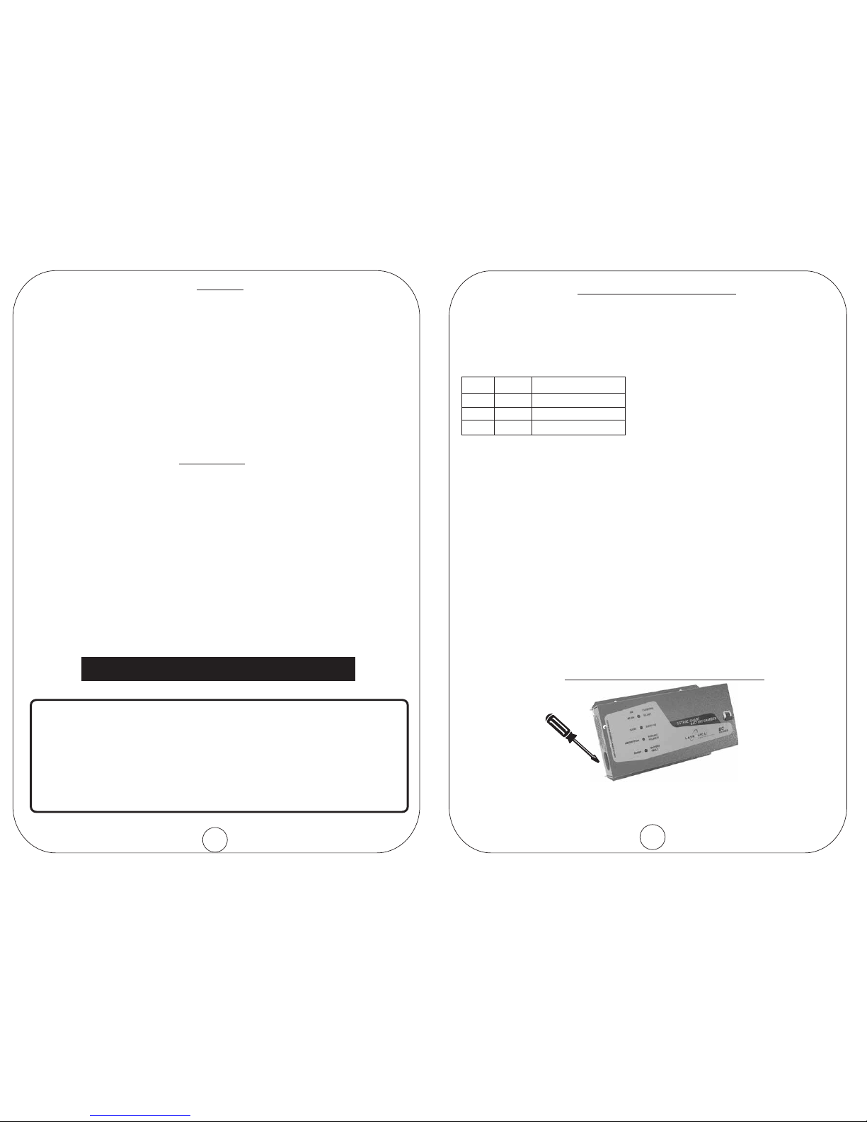
• Ensure the Charger is switched OFF before connecting to the Battery.
Turn the DC circuit breaker switch to the OFF position.
• Connect the Charger DIRECTLY to the battery terminals for best
performance.
• Battery leads marked RED = (positive), & BLACK = (negative).
exposed
air, battery gases, dust).
of
OBSERVE POLARITY
NOTE: Cables connecting the Charger to the battery are designed
to achieve maximum efficiency and output power:
DC CAB ES SHOULD NOT BE EXTENDED.L
2
WARRANTY CONDITIONS
All conditions and warranties expressed or implied by statute, common law,
equity, trade, custom, usage, or otherwise howsoever are hereby expressly
excluded to the maximum extent permitted by law. Where so permitted the
liability of Latronics for a breach of condition or warranty that cannot be
excluded is limited (at Latronics option) to the replacement or repair of the goods
or of acquiring equivalent goods or the cost of replacing or repairing the goods or
of acquiring equivalent goods. Latronics shall not be liable in any way whatsoever
for indirect or consequential loss or damage whatsoever (whether based on tort
or contract or otherwise).
!
!
!
!
!
!
!
!
!
Damage caused by unauthorized repair, alteration or substitution of non-
standard parts, incorrect installation, misuse, negligence, accident or similar
cause, or usage other than in accordance with the operating instructions, is not
covered under warranty.
Unauthorized opening of the goods will render the Warranty invalid.
The company may, at its discretion, agree to act as agent for the owner where
delivery is requested and all costs for cartage and insurance will be for the
owners account.
The replacement of any part or labour involved will not have the effect of
extending the period of the warranty of the goods.
Any faulty part replaced under Warranty becomes the property of the Company
for purpose of examination and claim under proprietary Warranty.
Registration Card must be returned within 3 months from date of purchase to
validate your 2-year warranty.
Keep your receipt as proof of purchase, should any difficulties arise concerning
the return of the registration card.
Chargers are supplied by the manufacturer, or the manufactures agents, under
the express condition that no responsibility is implied or accepted by the above
parties for any damage to any appliance, equipment or property associated with
the correct or otherwise operation of the Charger.
If service is required contact your local supplier/installer, or contact Latronics
direct on Ph: 61 7 5491 6988. Please ensure that you have the Charger Model
and Serial number available to enable prompt processing.
Please ensure that you have the Charger Model
and Serial number available to enable prompt processing.
11
INSTALLATION
DC WIRING

3
FAULT FINDING
HELPFUL HINTS
Should the charger appear to be malfunctioning we suggest the
following to eliminate any external problems.
1. Turn the charger OFF by disconnecting the AC plug and switching
the circuit breaker OFF to disconnect from the batteries.
2. Disconnect all DC battery leads. Clean all terminals by removing all
grease/corrosion on both leads and battery terminals.
3. Reconnect all leads and terminals and ensure all connections are
tight.
4. Turn the charger ON via the AC plug and DC circuit breaker on the
front panel. Observe the lights on the front panel for status and
mode of operation. Refer to charger operation section for full
explanation of indicators.
- If battery voltage is below 6V for 12V Charger or below
12V for 24V Charger, this will show as battery fault condition and
will not charge.
Note
* Make sure Green led comes ON when AC plug is connected and
turned ON. If Led is OFF check AC fuse.
* When the DC Circuit Breaker is turned ON, check that neither of
the Battery fault or reverse polarity indicators are flashing.
* Make sure terminals and leads are not corroded or faulty in
any way.
10
BATTERY SIZING
SAFETY
To ensure optimum performance, it is important to match the charger size
according to the capacity of your batteries. Use this formula as a general
guide:
Approx. Charger Size = Battery AH capacity ÷ 10
e.g. 300 AH ÷ 10 = 30A Charger
Minimum Battery size = 100 AH
Battery terminals require frequent care and maintenance. We recommend an
inspection of the batteries and the interconnecting cable connections once
every 1-3 months or as recommended by the battery manufacturer.
1. Regularly check all connections; make sure they are always tight.
Battery terminals are made of soft lead which will slowly compress over
time eventually causing loose connections.
2. Check all connections are free of corrosion. Remove any corrosion
the terminals with Vaseline or grease to help prevent future
corrosion.
3. Take specific gravity or SG readings of each cell using a hydrometer to
check the level and performance of each battery. Alternatively a
battery voltage reading for each cell will suffice but may not be
accurate for multiple batteries connected in parallel. Report any serious
imbalance to your system installer or battery supplier for corrective
action.
When working on batteries protective clothing and eye wear should be worn.
Extreme care should be taken not to short circuit any battery terminals
especially with tools. If in doubt have the work carried out by qualified
personnel.
and
coat
BATTERIES
MAINTENANCE

4
RADIO FREQUENCY INTERFERENCE
Radio Frequency Interference (RFI) is a phenomenon that exists in modern
society and is a problem in many areas of electronics. For users, RFI normally
presents itself in the form of static and/or interference when listening to an AM
radio and in unusual cases may interfere with TV reception.
Over the years Latronics has continued to invest significant time and effort in
the reduction of RFI related emissions from the entire product range, so that
they comply with the appropriate International and/or Australian Standards.
Even with this compliance, there are situations where RFI may still be a cause
for concern, and can differ greatly from installation to installation. Accordingly,
the following is a list of recommendations made to assist in the overall
reduction of RFI.
1. Separate DC and AC wiring. Avoid running DC and AC cables in the same
conduits and/or cable trenches. It is strongly recommended that DC and
AC wiring be separated by the greatest distance possible. In extreme
cases, the use of shielded conduit may be necessary.
2. Minimize length of DC cabling. DC cables can act as an aerial, therefore
all such cables should be kept as short as is practicable. For best
performance minimize DC cable length between charger and batteries and
if possible avoid the use of auxiliary DC loads.
3. 240Vac Earth. For household installations, it is recommended that a ”good”
Earth Stake is located as nearby any Charger as is possible.
4. AM and HF Radios. These types of radio equipment inherently suffer from
all forms of RFI, especially when the received signal level is weak. In such
cases reception can sometimes be improved by relocation of the radio
itself, alternatively the use of an appropriate external antenna and co-axial
cable may be necessary. External antennas should be located in a manner
that ensures maximum signal strength whilst affording the greatest
possible distance away from the Charger and batteries.
5. Televisions. TV signals are transmitted as FM waveforms. This type of
signal fundamentally reduces the effects of RFI, therefore the use of a
good antenna and feeder cable is normally sufficient to ensure quality
reception. Locating the television as far as possible from the Charger may
also improve picture clarity.
6. Mobile Installations. Due to the limitations of this type of installation, the
best results for the minimization of RFI are usually obtained by maximizing
the distance between the Charger and the Radio/Television.
9
WIRING DIAGRAMS for 12 & 24 Volts DC
CHARGING STAGES
+-
+- +-
12-Volt System
24-Volt System
TIME
BOOST ABSORPTION FLOAT
SILENT
VOLTAGE
EQUALIZE
(Every 90 days)
2days 14days

SAFETY
* All Latronics Chargers have an isolation rating of 3500V between AC
and DC via the toroidal transformer, which ensures extremely safe and
risk free operation.
* All the switching electronics and control circuitry are on the DC output.
* The single pole circuit breaker assembly ensures that when the Charger
is switched OFF, it is isolated from the battery supply.
* The active and neutral of the 240V AC input are electrically isolated
from the battery negative, battery positive, and earth connections.
* The Charger AC input is connected directly to the transformer input
winding.
* Latronics Chargers have the AC input (active and neutral) floating with
respect to the DC and Earth. The Earth connection is connected to the
case only. This configuration provides the highest safety and most
flexibility for installation wiring.
* Recommended minimum generator size 1500VA.
* The AC fuse is located internally on the main PCB.
Fuse rating is Antisurge/Slow blow 5A.
Charger Isolation and Safety
Please refer to relevant Australian Standards for safety procedures.
8
The whole of the supplies have been subjected to the Quality
System Requirements in accordance with the conditions of AS/NZS
ISO 9002: 1994.
All items are manufactured with full traceability.
All DC Series 5 Stage Smart Chargers conform to the C-Tick mark
for the EMC emission standard EN55014.
STATEMENT OF QUALITY ASSURANCE
DIP SWITCH SETTINGS
In order to access these options you have to open the Charger. Before
altering the settings switch Charger OFF, adjust the setting and switch
Charger back ON again. We recommend these adjustments be carried
out by qualified personnel or your system installer.
ON ON Lead Calcium
ON OFF AGM
OFF ON Gel/SLA
OFF OFF Flooded (Factory Setting)
ON = Special Factory Test Function. Do not use for normal operation
OFF = Factory Settings
SW1 SW2 Battery Type
SW3 Temperature
SW4 Equalise
SW5 Silent Mode
SW6 Special
ON = COLD
OFF = HOT (Factory Settings)
ON = ENAB E (Factory Settings)
OFF = DISAB E
- Equalise Function is disabled when AGM/GEL battery type is
selected.
ON = ENAB E (Factory Settings)
OFF = DISAB E
L
L
L
L
*Note
AC WIRING
5
LOCATION OF DIP SWITCHES
Removable plug for access to selector switches.
Turn Charger OFF and disconnect AC power cord before removing plug.
: Replace plug before reconnecting Charger.Note

67
When the charger is first switched on all LED’s light up for one second while the
microprocessor performs a start up and system check procedure.
INDICATOR
LED is ON during boost mode of charge cycle.
LED will flash for a battery fault condition or
no battery connected.
*Note: LED will flash if DC Circuit Breaker is
OFF.
DC CIRCUIT BREAKER
In line with battery positive lead
Push up - to turn ON
Push down - to turn OFF and
disconnect from batteries.
AC POWER CORD
Located on end.
DC BATTERY LEADS
Located on end.
RED = Battery Positive
BLACK = Battery Negative
CHARGER OPERATION
INDICATOR
LED is OFF when no AC power is present.
LED is ON when AC power is present.
LED will flash when charger enters silent mode
of charging cycle.
INDICATOR
LED is ON when charger is in float mode of
charge cycle. LED will flash during the
equalisation mode of the charge cycle.
INDICATOR
LED is ON during absorption mode of charge
cycle.
LED will flash when battery leads are reversed.
COOLING FAN
Thermostatically and load controlled fan.
Only operates when required.
SELECTOR SWITCHES
Remove plug for access to selector switches.
See page 5 for details.
This manual suits for next models
1
Table of contents