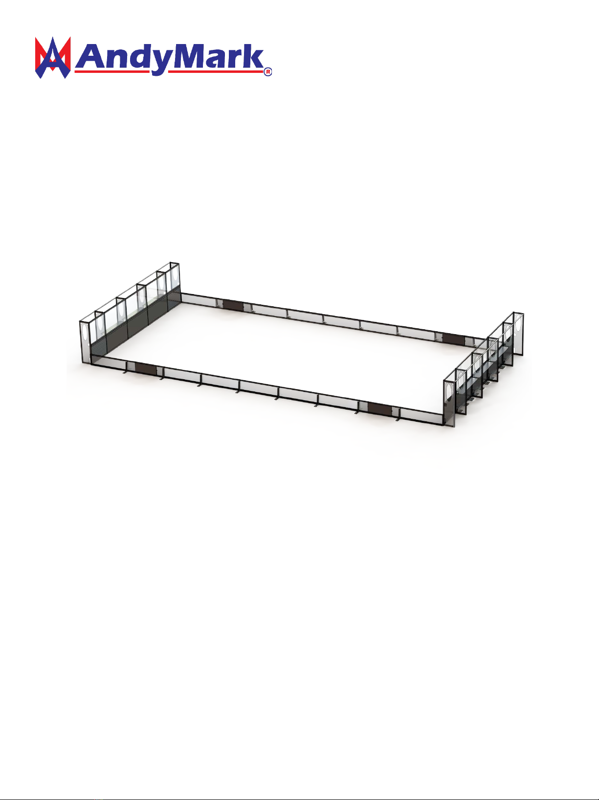
AndyMark AM-2800 User manual

ASSEMBLY and CASE PACKING GUIDE
for AndyMark Extruded Field Perimeter (am-2800)

Side Rail Case Inventory and Assembly
SIDE RAIL CASE INVENTORY
Part
QTY
Picture
Side Rail Section (am-2801)
10
Gate Section (am-2802)
4
Left End Rail Section (am-2803)
2
Right End Rail Section (am-2821)
2
Outrigger (am-2810)
16
Corner Pin (am-2981)
5
Rev 1.2 10/23/14 2

UPRIGHTS CASE INVENTORY
Part
QTY
Picture
Right End Upright (am-2804)
2
Middle Upright (am-2806)
8
Left End Upright (am-2809)
2
Station Overhead Pipe (am-2811)
6
Rev 1.2 10/23/14 3

END STATION CASE INVENTORY
Part
QTY
Picture
End Station Plate Panel (am-2808)
6
End Station Poly Panel (am-2807)
6
Anchor (am-2991)
18
CORNER STATION CASE INVENTORY
Part
QTY
Picture
Corner Station Plate Panel (am-2805)
6
Corner Station Poly Panel (am-3028)
6
Corner Overhead Pipe (am-2812)
18
Rev 1.2 10/23/14 4

Side Rail Assembly
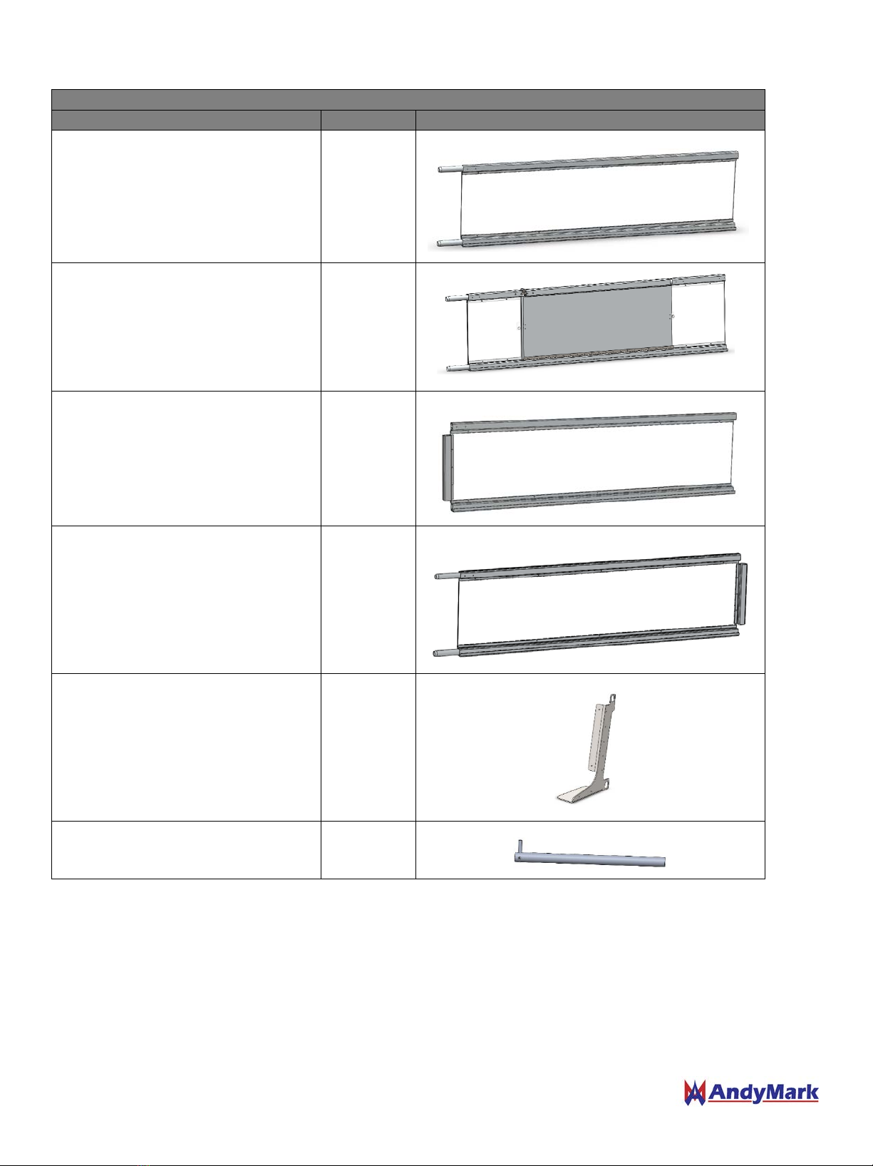
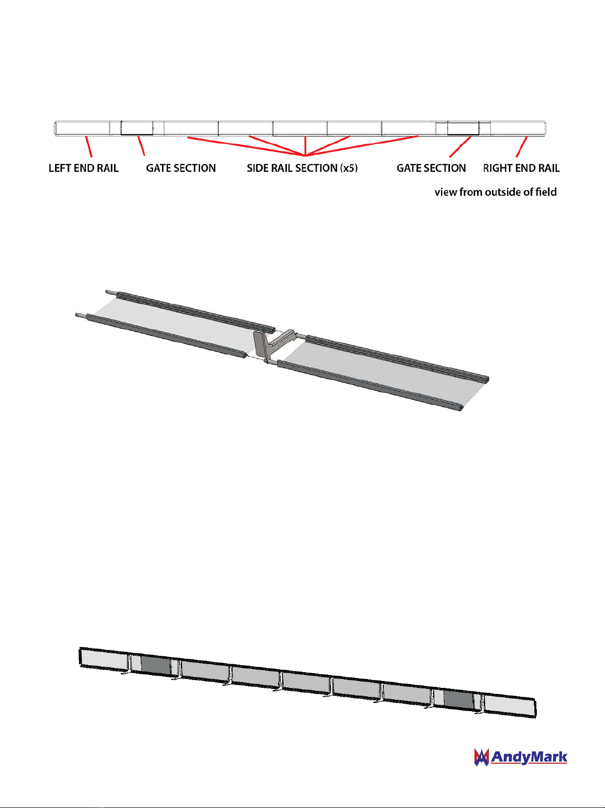
1. Lay out all Guardrail, Outrigger and Human Player Barrier segments. All of the side rail sections are identical
and the gates are identical. The side should be laid out in the following order. Pieces can be labeled for future
assembly.
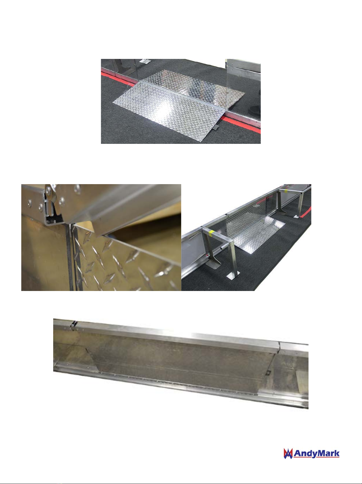
2. Connect the segments by inserting the smaller tube into the larger on the top and bottom rail. Be sure to
slide the Outriggers in between each panel section.
NOTE: The Velcro foot on the outrigger should be on the same side as the Velcro bottom of the side rail. The
flat edge of the panel will face the inside of the field.
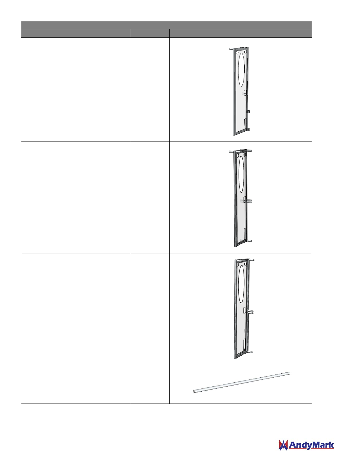
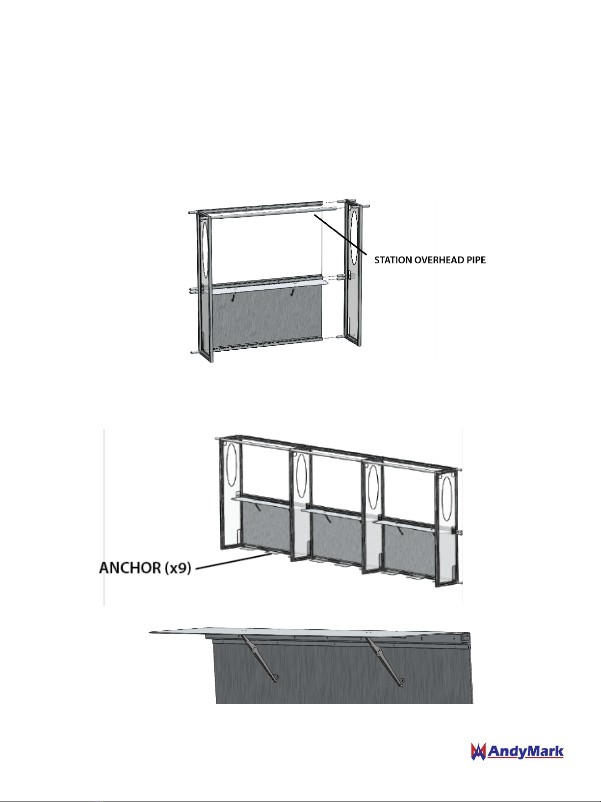
For 2014 also be sure to slide the Human Player Barrier Brackets and Poles on as well
NOTE: There are two HP barrier poles per side that are longer in length than the others. Those go on each end.
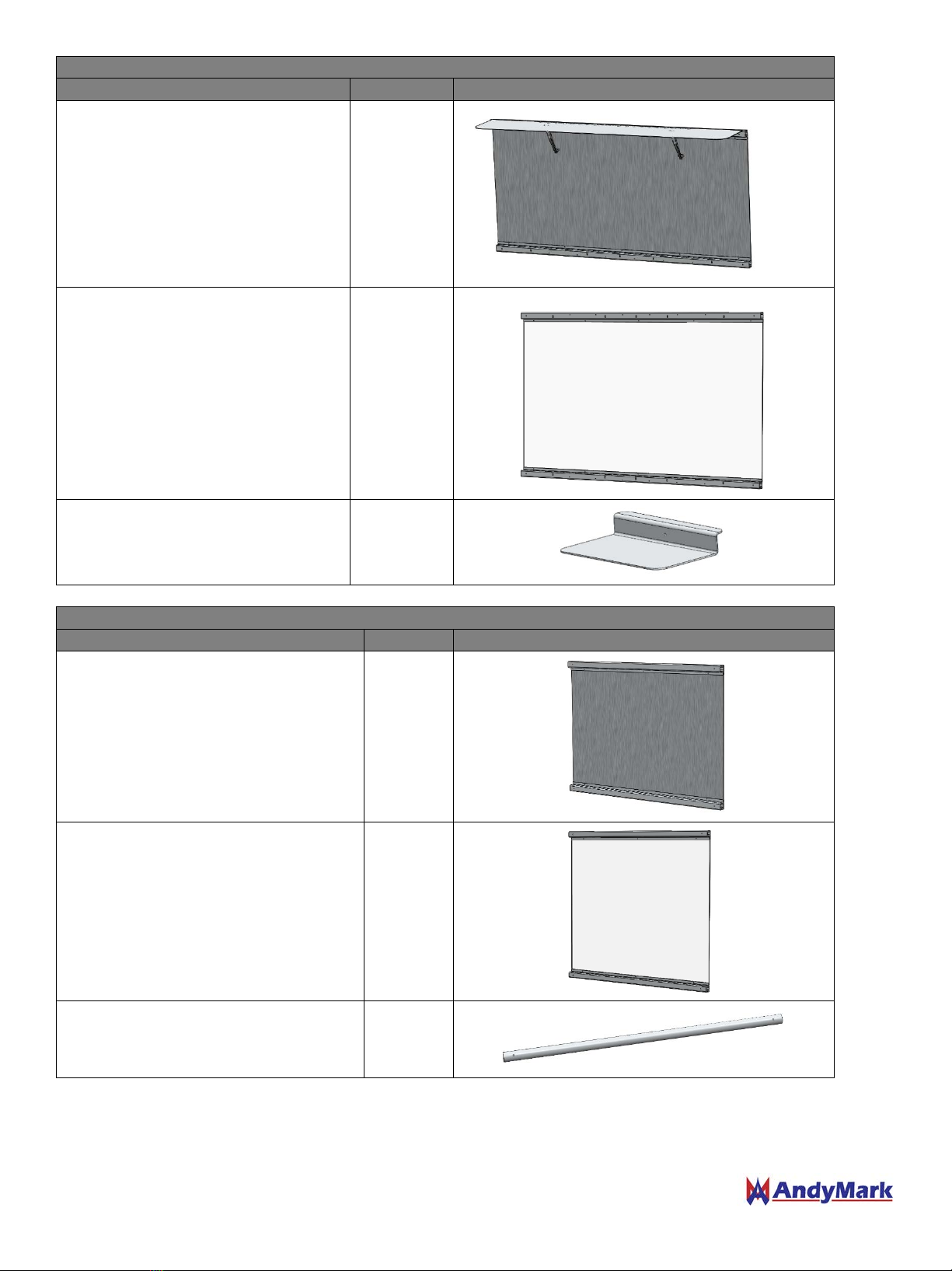
3. Align the edge of the bottom Velcro angle with the measured line for the side border edge
4. Align the end of the panel row with one measured end line on the field
5. Ensure there are no gaps between the panels
6. Use four (4) or more people to flip the entire Side Border assembly simultaneously into the upright position.
The crew should be positioned on the inside of the Field. Make sure the inside bottom line remains located on
the respective chalk line.
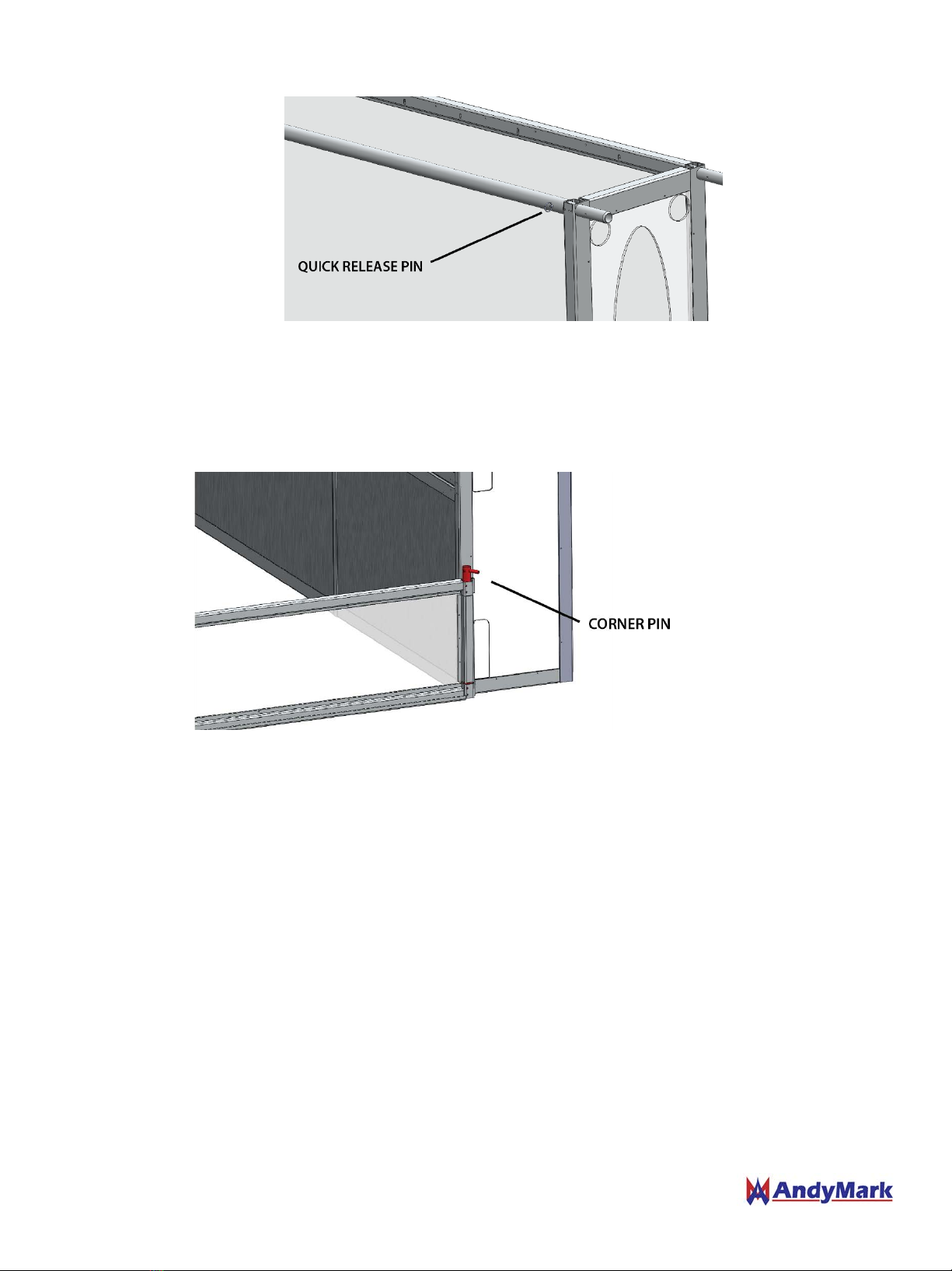
For 2014, when the Field Border is in the correct position, flip the Human Player Barrier to the outside of the
Field. Be sure to pin the poles of the Human Player Barrier into position after it is in place.
Rev 1.2 10/23/14 5

Driver Station Assembly
The driver stations can be built either in place using a plastic sheet between the Velcro and the carpet or face down on
the floor and be stood up into place after assembly.
Build the driver stations from the field center outward
1. Center an end plate panel on the centerline of the field. The panel is 72” wide and the edges of the center
panel should sit 36” off the marked field centerline
2. Slide a middle upright onto each side of the center plate panel and the center poly panel. Ensure a station
overhead pipe sits between the back pins of the uprights. You may need a few people to ensure the pieces are
slide in straight. A mallet may be used to encourage the panels to slide together. Be careful not to bend the
pins.
3. Continue sliding pieces together to create a wall 3 driver stations wide, centered on the field centerline.
4. Once the wall is built and in line with the measured chalk lines, secure the backside with 3 anchors per driver
station.
5. Lift and lock driver station shelves into place.
Rev 1.2 10/23/14 6

6. Quick Release Pins can be added to the Station Overhead Pipe to ensure the uprights are locked into position
during match play.
Once this is built the low goals can be added to the corner for the 2014 game or the corner station panels can be
added instead.
7. Pin the End Stations to the side rails at each corner using a corner pin.
NOTE: The field perimeter assembly may be modified from year to year to accommodate
different game specific components.
Rev 1.2 10/23/14 7

Using the Gate
In between matches the gate can be opened and the ramps will sit on the floor. These ramps may flex when walked
on but should not permanently deform.
During match play the gate ramp on the inside of the field sits in the channel in the top gate rail. The top rail pin can
be slid into place to lock the gate closed.
The magnet helps to assist in holding the ramp in place while closing the top rail.
For transportation and storage both the outer and inner gate ramps can be locked in place by the top rail.
Rev 1.2 10/23/14 8

Packing the End Station Case
The Ends Station Case holds the poly and plate panels for each side of the field. One
side of the field fits on each side of the case.
END STATION CASE CONTENTS
Part
QTY
End Station Plate Panel (am-2808)
6
End Station Poly Panel (am-2807)
6
Anchor (am-2991)
18
1. Place an End Station Poly Panel into the end panel case with the flat edge facing the back of the case.
Rev 1.2 10/23/14 9

2. Place an End Station Plate Panel into the end panel case with the flat edge facing outwards. The plate panel
should sit on the lip of the poly panel.
3. Place the remaining panels in the case. Alternating poly and plate panels.
4. Strap panels down to secure into place on the cart.
Rev 1.2 10/23/14 10

Packing the Uprights Case
The uprights case holds uprights for both sides of a field. One field end can fit on each shelf as shown below.
Pieces should be placed into the case in order, otherwise they will not fit.
UPRIGHTS CASE CONTENTS
Part
QTY
Right End Upright (am-2804)
2
Middle Upright (am-2806)
8
Left End Upright (am-2809)
2
Station Overhead Pipe (am-2811)
6
1. Place a right end upright into the case. The pins should face outwards and the corner without pins should be
at the top right.
2. Place middle upright #1 into the case. The corner without pins should be on the bottom left. The other pins
should sit above and to the right of the right end upright already in the case.
Rev 1.2 10/23/14 11

3. Place middle upright #2 into the case. The corner without pins should be on the top right. The other pins
should sit on the floor and to the left of the pieces already in the case.
4. Place middle upright #3 into the case. The corner without pins should be on the bottom left. The other pins
should sit above and to the right of the uprights already in the case.
5. Place middle upright #4 into the case. The corner without pins should be on the top right. The other pins
should sit between the pins of the uprights already in the case as shown.
6. Place a left end upright into the case. The corner without pins should be on the bottom left. The other pins will
sit on the uprights already in the case as shown.
Rev 1.2 10/23/14 12

Packing the Side Rail Case
The side rail case holds the side rail pieces for a full field. One field side can fit on each shelf. Outriggers and
corner pins can fit in this case.
1. Place Right End Rail flat side down into case with bottom towards the back of the case.
SIDE RAIL CASE CONTENTS
Part
QTY
Side Rail Section (am-2801)
10
Gate Section (am-2802)
4
Left End Rail Section (am-2803)
2
Right End Rail Section (am-2821)
2
Outrigger (am-2810)
16
Corner Pin (am-2981)
4
Rev 1.2 10/23/14 13

2. Place Gate Rail Section (with ramps locked into place) with flat side up. The rail sections should nest in one
another and the bottom lip should overhang the first rail section. The pins should face the same direction as
the Right End Rail.
3. Place Side Rail Section flat side down with bottom side flush with the back side of the case.
4. Continue alternating rail sections to fill the case.
5. Place Outriggers in case next to the rail sections.
Rev 1.2 10/23/14 14

Packing the Corner Station Case
The Corner Station Cart holds all 4 Corner Station Sections.
1. Place Corner Station Poly Panel onto Corner Station Case with the flat side facing towards the back of the case.
2. Place Corner Station Plate Panel into the Corner Station Case with the flat edge facing away from the back of
the cart. The plate panel should sit on the lip of the poly panel.
CORNER STATION CASE CONTENTS
Part
QTY
Corner Station Plate Panel (am-2805)
4
Corner Station Poly Panel (am-3028)
4
Corner Overhead Pipe (am-2812)
4
Rev 1.2 10/23/14 15

3. Place the remaining panels in the case. Alternating poly and plate panels.
4. Strap panels down to secure into place on the cart.
Rev 1.2 10/23/14 16
Table of contents
Other AndyMark Industrial Equipment manuals
Popular Industrial Equipment manuals by other brands

UnionSpecial
UnionSpecial BCE300PD Original instructions

Siemens
Siemens AS-Interface operating instructions

Paasche Airbrush
Paasche Airbrush HB-16-2F instruction manual

Raytools
Raytools BM110 Series user manual

Teka
Teka LMD 501 SPA operating instructions

Venture Industries
Venture Industries VMS ATEX Operating and assembly instructions