ABB ACQ580-01 Series Installation manual

1
This guide is applicable to the North American product types. There is a separate guide for the global (IEC) product types.
Safety instructions
WARNING! Obey these instructions. If you ignore them, injury or death, or damage to the equipment can occur. If
you are not a qualified electrical professional, do not do electrical installation or maintenance work.
WARNING! Before you activate the automatic fault reset or automatic restart functions of the drive control
program, make sure that no dangerous situations can occur. These functions reset the drive automatically and
continue operation after a fault or supply break. If these functions are activated, the installation must be clearly
marked as defined in IEC/EN/UL 61800-5-1, subclause 6.5.3, for example, “THIS MACHINE STARTS AUTOMATICALLY”.
• Do not do work on the drive, motor cable, motor, or control cables when the drive is connected to the input power.
Before you start the work, isolate the drive from all dangerous voltage sources and make sure that it is safe to start the
work. Always wait for 5 minutes after disconnecting the input power to let the intermediate circuit capacitors
discharge.
• Do not do work on the drive when a rotating permanent magnet motor is connected to it. A rotating permanent
magnet motor energizes the drive, including its input and output terminals.
• Do not tilt the drive. The drive is heavy and has a high
center of gravity. It can topple accidentally.
• All frames have lifting eyes to assist with lifting.
• Frames R3: Lifting the drive with a lifting device is
recommended since weight exceeds 50 lb (23 kg)
1. Unpack the drive
Keep the drive in its package until you are ready to install it.
Make sure that these items are included:
• drive
• mounting template
• control panel (factory-installed inside the cover)
• quick installation and start-up guide
• multilingual residual voltage warning stickers
• hardware and firmware manuals, if ordered
• options in separate packages, if ordered.
Make sure that there are no signs of damage to the items.
2. Reform the capacitors
If the drive has not been powered up for a year or more, you must reform the DC link capacitors. See Related documents or
contact ABB technical support.
3. Select the cables and fuses
Input power cable: Use symmetrical shielded cable (VFD cable) for the best EMC performance. NEC installations: Conduit
with continuous conductivity (Type EMT, RMC or LFMC) is also allowed and must be grounded on both ends. Non-metallic
conduit (Type LFNC) will not suppress EMC noise. If noise issues are occurring, changing to continuously conductive
conduit or shielded cable will be beneficial in most situations. Do not run input power wiring and motor wiring in the same
conduit.
Motor cable: ABB recommends symmetrically shielded VFD motor cable to reduce bearing current and wear and stress on
motor insulation and to provide the best EMC performance. Although not recommended, conductors inside conduit are
allowed in NEC installations. Continuously conductive (metallic) conduit (Type EMT, RMC or LFMC) should be grounded on
both ends. Non-metallic conduit (Type LFNC) will not suppress EMC noise. If noise issues are occurring, changing to
continuously conductive conduit or shielded cable will be beneficial in most situations. Use separate conduit run for each
motor. Do not run input power wiring and motor wiring in the same conduit.
Wet locations and underground cable: Use liquid-tight conduit in wet, dirty, dusty, corrosive or similar locations when
using conduit. Usage of Non-metallic conduit underground and in wet locations is allowed. However, these installations
inherently have an increased chance for nuisance problems due to the potential for water/moisture in the conduit. Water/
Documentation in other languages Ecodesign information
(EU 2019/1781 and SI 2021 No. 745) About this document
3AXD50001020149 Rev A EN
2023-04-24
© 2023 ABB. All rights reserved.
Original instructions.
—
DRIVES FOR WATER
ACQ580-01 UL Type 4X (IP66) drives, NEC types
Quick installation and start-up guide

2
moisture in the conduit increases the likelihood of VFD faults or warnings. Proper installation is required to make sure there
is no intrusion of water/moisture.
For more information: see Hardware Manual, section Electrical Installation – North America
•Power cable types: Use only copper conductors.
•Current rating: max. load current.
•Voltage rating (minimum): 600 V AC cable is accepted for up to 500 V AC, 750 VAC cable is accepted for up to 600
V AC, 1000 V AC cable is accepted for up to 690 V AC.
•Temperature rating: Use 75 °C conductors minimum, except for drives with a voltage rating of 575 Vac (-6) with
ambient temperature above 40 °C, use 90 °C conductors. Insulation temperature can be higher as long as the
ampacity is based on 75 °C conductors.
•Size: Refer to Ratings, fuses and typical power cable sizes for the typical cable sizes and to Input power cables with
disconnect switch option (F254) for the maximum cable sizes.
• Select the control cables. Use double-shielded twisted-pair cable for analog signals. Use double-shielded or single-
shielded cable for the digital, relay and I/O signals. Do not run 24 V and 115/230 V signals in the same cable.
• Protect the drive and input power cable with the correct fuses. Refer to Ratings, fuses and typical power cable sizes.
4. Examine the installation site
Examine the site where you will install the drive. Make sure that:
• Site is dry and clean during the installation. Drive is not watertight until installation is complete.
• The installation site is sufficiently ventilated or cooled to remove heat from the drive.
• The ambient conditions meet the requirements. Refer to Ambient conditions.
• Outdoor installations: protect the drive from direct sunlight to prevent overheating. Drive is UV resistant.
• The installation surface is as close to vertical as possible and strong enough to support the weight of the drive. Refer to
Weights and free space requirements
• The installation surface, floor and materials near the drive are not flammable.
• There is sufficient free space around the drive for cooling, maintenance and operation. For the minimum free space
requirements, refer to Weights and free space requirements
• There are no sources of strong magnetic fields such as high-current single-core conductors or contactor coils near the
drive. A strong magnetic field can cause interference or inaccuracy in the operation of the drive.
5. Install the drive on the wall
Select fasteners that comply with local requirements applicable to wall surface materials, drive weight and application.
Prepare the installation site
1. Make marks with the help of the mounting template. Remove the mounting template before you install the drive on the
wall.
2. Drill the holes and put anchors or plugs into the holes.
3. Install the screws. Leave a gap between the screw head and mounting surface.
Distance between mounting holes
Frame
size
Width (a) Height (b)
mm in mm in
R1 175 6.89 497 19.57
R2 175 6.89 581 22.87
R3 244 9.61 622 24.50
Your drive's frame size is shown on the drive
nameplate.
a
b
13
× 4
2M6 (¼”)

3
Put the drive on the wall and tighten the screws
6. Remove the cover(s)
7. Optional - remove the cable/conduit box (to modify holes) - 4 screws
8. Attach a residual voltage warning sticker to the drive in the local language
To the control panel mounting platform.
9. Make sure that the drive is compatible with the grounding system
You can connect all drives to a symmetrically grounded TN-S system (center-grounded wye) without any modifications to
the built-in EMC filter or varistors. If you install the drive to a different system, reconfigure the EMC and VAR screws as
shown in the table below. The table also shows the optional modifications available.
Frame
size Connection TN System
NEC
(B066)
Default3)
TN System
IEC
(B063)
Default4)
Corner-grounded delta
and Midpoint-grounded
delta system
IT system TT system
R1…R3 EMC (DC) None or plastic Metal2) None or plastic1) None or plastic1) None or plastic1)
VAR Metal Metal None or plastic None or plastic1) None or plastic1)
1) Metal screw must not be used.
2) Optional, for better noise filtering.
3) NEC (UL) drives (+B066) have these screws installed by default.
4) IEC drives (+B063) have these screws installed by default.
3
1
2
8 x T20 Torx
Tighten to 2.2 ft-lb (3 Nm)
14 x T20 Torx
Tighten to 2.2 ft-lb (3 Nm)

4
10. Measure the insulation resistance of the power cables and the motor
Measure the insulation resistance of the input cable before you connect it to the
drive. Obey local regulations.
Measure the insulation resistance of the motor cable and motor when the cable
is disconnected from the drive. Measure the insulation resistance between each
phase conductor and the PE conductor. Use a measuring voltage of 1000 V DC.
The insulation resistance of an ABB motor must be more than 100 Mohm
(reference value at 25 °C or 77 °F). For the insulation resistance of other motors,
see the manufacturer’s instructions. Moisture inside the motor decreases the
insulation resistance. If you think that there is moisture, dry the motor and do
the measurement again.
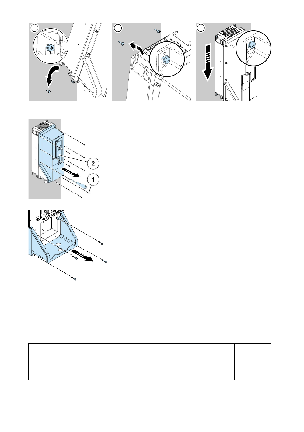
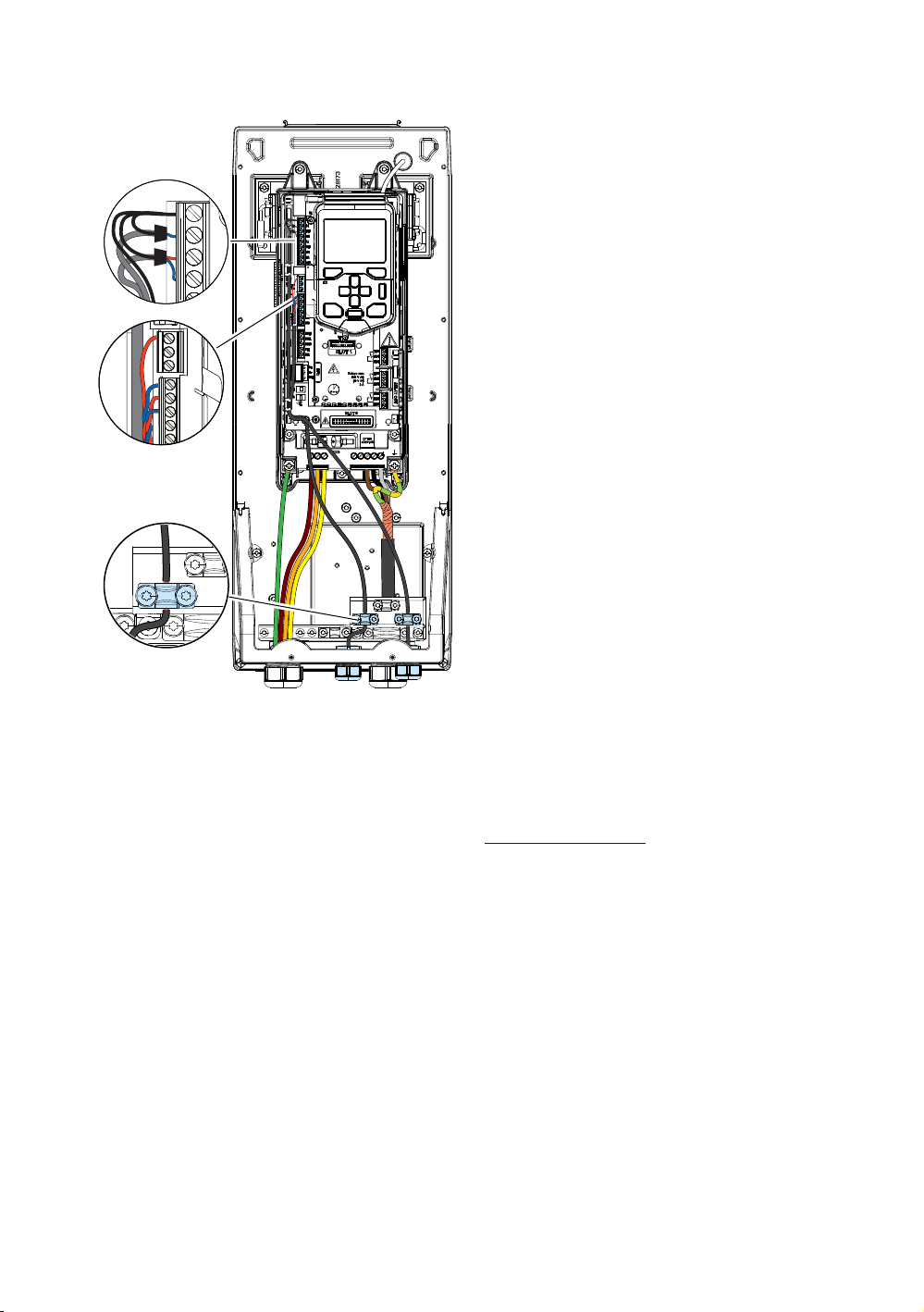
11. Connect the power cables
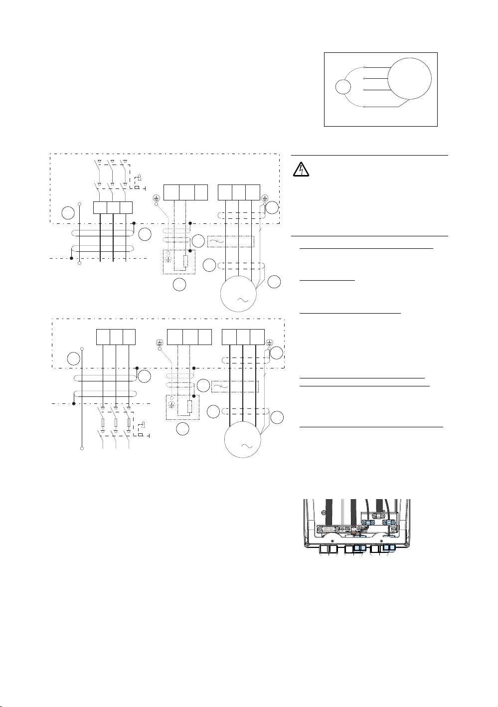
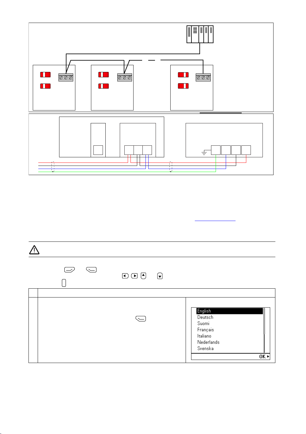
UL (NEC) connection diagram with symmetrically shielded cable or conduit
Connection procedure
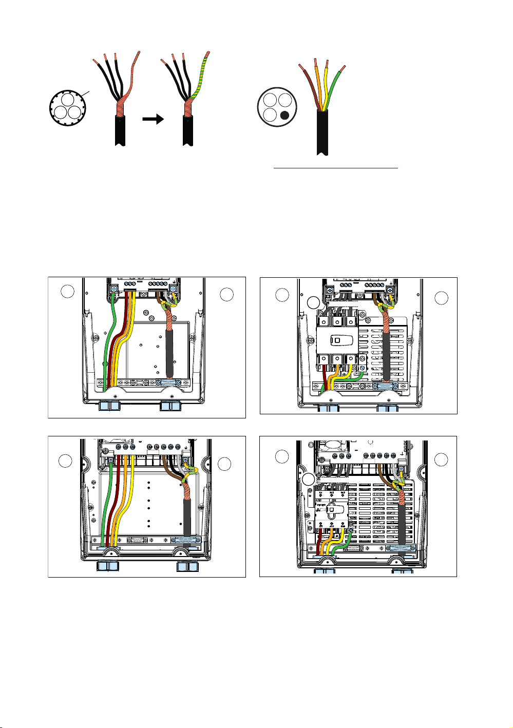
1. Prepare the power cables (shielded cable).
•Prepare the ends of the input power cable and motor cable as illustrated in the applicable figure (b).
•Install the conduit fitting or cord grip (not supplied).
•Slide the cables through the fitting or grip. After wires are terminated, complete installation of conduit and/or
tighten the cord grip to achieve a water-tight seal.
U1-PE, V1-PE, W1-PE
U1
V1
W1
PE
M
3~
ohm
WARNING: If installing drive indoors or
outdoors in a wet, dirty, dusty,
corrosive or similar environment, all
cable, conduit and fittings must be approved
for use in this type of environment. Fittings
must be properly tightened to the drive such
that no leakage occurs. Failure to follow these
instructions can lead to injury or death, or
damage to the equipment.
a. Insulated ground conductor in a conduit:
Ground to drive's PE terminal and to the
distribution panel ground bus. For a VFD
cable installation see d.
b. Conduit ground: Bond the conduit to the
drive's conduit box and to the distribution
panel enclosure. For a VFD cable installation
see c.
c. Shield of a VFD shielded cable: Ground the
shield 360° under drive's grounding clamp,
then twist with the ground conductors and
connect under the drive's ground terminal.
Ground the shield also 360° at the motor end,
then twist and connect under the motor's
ground terminal. For a conduit installation
see b.
d. Symmetrically constructed grounding
conductors inside a VFD shielded cable:
Twist together, combine with the shield and
connect under the drive's ground terminal
and under the motor's ground terminal. For a
conduit installation see a.
e. External brake resistor connection (if used):
For a conduit installation see a and b. For a
VFD cable installation see c and d. In
addition, cut the third phase conductor
which is not needed for the brake resistor
connection.
f. If necessary, install an external filter (du/dt,
common mode, or sine filter). Filters are
available from ABB.
Note: UL (NEC) installation can include separate insulated conductors
inside a conduit, shielded VFD cable in conduit, or shielded VFD cable
without conduit. The normal dashed symbol (c) in this diagram
represents the shield of shielded VFD cable. The same solid symbol (b)
represents conduit.
PE
PE
L1 L2 L3 R-
U1 W1
M
3
T1/U T2/V T3/W
V1
L1 L2 L3
PE
3
UDC-
R+
UDC+
a
b
cd
d
e
f
PE
PE
2T1 4T2 6T3
L1 L2 L3
R-
U1 W1
M
3
T1/U T2/V T3/W
V1
PE
3
UDC-
R+
UDC+
Drive with disconnect option
Drive without disconnect option
a
b
c
d
e
f
d
Grounding clamps

5
2. Prepare the power cables (conduit):
•Attach the cable conduit fittings for the motor and input cabling to the cable entry holes
3. Connect the power cables. For the tightening torques, refer to Terminal data for power connections.
• Slide the conductors through the conduit.
• Connect the conductors:
•Connect the phase conductors of the motor cable to terminals T1/U, T2/V and T3/W. Connect the twisted shield of
the cable to the grounding terminal. (3a)
•Connect the grounding conductor to the grounding terminal. Connect the phase conductors of the input power
cable as was done for the motor cabling. Use terminals L1, L2 and L3 if no disconnect option is present. When an
optional disconnect is present, connect the input power cable conductors to the disconnect switch at terminals 2T1,
4T2 and 6T3. (3b)
•If used, connect the brake resistor cables.
4. Secure the conduits outside the unit mechanically. In wet, dirty, dusty, corrosive or similar locations, all fittings must be
properly tight and secured such that no leakage can occur.
12. Connect the control cables
Make the connections according to the application. Keep the signal wire pairs twisted as near to the terminals as possible.
1. Attach cable fitting/grip to the small cable entry hole. Slide the control cables through the cable fitting/grip.
2. Ground the shield at one end of the cable only. If you ground the shield at the source of the signal, do not ground it at
the SCR terminal.
3. Tie all control cables to the provided cable tie mounts.
4. Secure the conduit outside the unit mechanically. In wet, dirty, dusty, corrosive or similar locations, all fittings must be
properly tightened and secured such that no leakage can occur.
PE
Conduit
R1…R2 without disconnect
PE
L1 L2 L3
INPUT BRAKE RES
R+
UDC+
R- T1/U T2/V T3/W
MOTOR
3a
3b
R3 without disconnect
PE
L1 L2 L3
INPUT BRAKE RES
R+
UDC+
R- T1/U T2/V T3/W
MOTOR
3a
3b
R3 with disconnect
PE
L1 L2 L3
INPUT
BRAKE RES
R+
UDC+
R- T1/U T2/V T3/W
MOTOR
1
3a
3b
R1...R2 with disconnect
PE
L1 L2 L3
INPUT BRAKE RES
R+
UDC+
R- T1/U T2/V T3/W
MOTOR
1
3a
3b
Note 1: Internal fuse block is wired between the disconnect and the
drive

6
Default I/O connections (Water default)
Total load capacity of the auxiliary voltage output +24V (X2:10) is 6.0 W (250 mA / 24 V DC).
Terminals Wire size Tightening torque
+24V, DGND, DCOM, B+, A-, DGND, Ext. 24V 0.2 … 2.5 mm2 (24 … 14 AWG) 0.5 … 0.6 N·m (5 lbf·in)
DI, AI, AO, AGND, RO, OUT, IN, SGND 0.14 … 1.5 mm2 (26 … 16 AWG)
4BGFUPSRVFPGG450#PUIDJSDVJUTNVTUCFDMPTFEGPSUIF
ESJWFUPTUBSU5IFESBXJOHTIPXTUIFTJNQMJGJFEDPOOFDUJPO
PGBTBGFUZDJSDVJUUISPVHITBGFUZDPOUBDUT*G450JTOPUVTFE
MFBWFUIFGBDUPSZJOTUBMMFEKVNQFSTJOQMBDF4FFBMTPTFDUJPO
4BGFUPSRVFPGG450
R6… R9 only: Ext 24V AC/DC input to power up the
control unit when the main supply is disconnected.

7
Control cable installation examples
This section shows examples for routing the control cables. Utilize the retaining clips along the edge of the controller.
EIA-485 embedded fieldbus connection
You can connect the drive to a serial communication link with a fieldbus adapter module or the embedded fieldbus
interface. The embedded fieldbus interface supports Modbus RTU.
To configure Modbus RTU communication with the embedded fieldbus:
1. Connect the fieldbus cable and the required I/O signals. Use Belden 9842 or equivalent. Belden 9842 is a dual twisted,
shielded pair cable with a wave impedance of 120 Ohms.
2. If the drive is at the end of the fieldbus, set the termination switch to ON.
3. Power up the drive and set the required parameters. Refer to Motor overload protection.
BRAKE RES
T2/V T3/W
MOTOR
PE
L1 L2 L3
INPUT BRAKE RES
R+
UDC+
R- T1/U T2/V T3/W
MOTOR

8
Overview and connection diagrams for connecting the drive to the fieldbus are shown below.
• Connect the cable shields together at each drive, but do not connect them to the drive.
• Connect the shield only to terminal “G” (ground) in the automation controller.
• Connect the DGND conductor to terminal “R” (reference) in the automation controller.
13. Install optional modules, if included in the delivery
14. Install the cover(s)
The cover installation procedure is the opposite of the removal procedure. Refer to Remove the cover(s). Tighten and secure
the eight screws to 2.2 ft-lb (3 Nm) using T20 Torx screwdriver
15. Start up the drive
WARNING! Before you start up the drive, make sure that the installation is completed. Make sure also that it is safe
to start the motor. Disconnect the motor from other machinery if there is a risk of damage or injury.
Use the control panel to do the start-up procedure. The two commands at the bottom of the display show the functions of
the two softkeys and located below the display. The commands assigned to the softkeys are different
depending on the context. Use the arrow keys , , and to move the cursor or change values depending on the
active view. Key shows a context-sensitive help page.
1. Power up the drive. Make sure that you have the motor name plate data available.
2. The First start assistant guides you through the first start-up.
The assistant begins automatically. Wait until the control panel shows
the language selection screen.
Select the language you want to use and press (OK).
Note: After you select the language, it takes a few minutes for the
control panel to wake up.
ON
TERM
ON
BIAS
X5
Termination ON1)
Bias ON2)
Drive
ON
TERM
ON
BIAS
X5
Termination OFF
Bias OFF
Drive
Fieldbus controller
Fieldbus
ON
TERM
ON
BIAS
X5
Termination OFF
Bias OFF
Drive
Termination ON1)
1) The devices at both ends
on the fieldbus must have
termination set to ON.
2) One device, preferably at
the end on the fieldbus,
must have bias set to ON.
B+
A -
DGND
X5
29 30 31 GR-+
1
X1
SCR
Automation controller
Drive control
unit
?

9
Motor overload protection
The motor thermal overload protection is set to motor current and motor class curves as default. Motor thermal overload
protection can also be measured using motor temperature devices or can be estimated using a motor model defined by
3. Select Start set-up and press (Next).
4. To complete the first start assistant, select the values and settings
when prompted by the assistant. Continue until the panel shows that
the first start is complete.
When the panel shows that the first start is complete, the drive is ready
for use. Press (Done) to enter the Home view.
5. The Home view shows the values of the selected signals.
6. Make additional adjustments, for example, pump protections, starting
from the Main menu. Press (Menu) in the Home view to enter the
Main menu.
Select Primary settings and press (Select) (or ).
To get more information on the Primary settings menu items, press
to open the help page.
?

10
parameters. To enable protection using motor model parameters or measurement devices set parameter 35.11 and
subsequent parameters through 35.55.
To adjust motor class curves (default is class 20), change parameters 35.56 and
35.57.
Use the information key ( ) on the drive control panel for more information on setting group 35 parameters. You must set
the drive overload parameters correctly, or motor damage could occur.
Fieldbus communication
To configure the embedded fieldbus communication for Modbus RTU, you must set at least these parameters:
Other parameters related to the fieldbus configuration:
Parameter Setting Description
20.01 Ext1 commands Embedded
fieldbus
Selects fieldbus as the source for the start and stop commands when
EXT1 is selected as the active control location.
22.11 Ext1 speed ref1 EFB ref1 Selects a reference received through the embedded fieldbus interface
as speed reference 1. Use this parameter with the vector motor control
mode.
28.11 Ext1 frequency ref1 EFB ref1 Selects a reference received through the embedded fieldbus interface
as frequency reference 1. Use this parameter with the frequency motor
control mode.
58.01 Protocol enable Modbus RTU Initializes embedded fieldbus communication.
58.03 Node address 1 (default) Node address. There must be no two nodes with the same node
address online.
58.04 Baud rate 19.2 kbps (default) Defines the communication speed of the link. Use the same setting as
in the master station.
58.05 Parity 8 EVEN 1 (default) Selects the parity and stop bit setting. Use the same setting as in the
master station.
58.06 Communication
control
Refresh settings Validates any changed EFB configuration settings. Use this after
changing any parameters in group 58.
58.14 Communication loss
action
58.17 Transmit delay 58.28 EFB act1 type 58.34 Word order
58.15 Communication loss
mode
58.25 Control profile 58.31 EFB act1 transparent
source
58.101 Data I/O 1
…
58.114 Data I/O 14
58.16 Communication loss
time
58.26 EFB ref1 type 58.33 Addressing mode
?

11
Warnings and faults
Ratings, fuses and typical power cable sizes
Warning Fault Aux. code Description
A2A1 2281 Current calibration Warning: Current calibration is done at the next start.
Fault: Output phase current measurement fault.
A2B1 2310 Overcurrent The output current is more than the internal limit. This can also be caused by
an earth fault or phase loss.
A2B3 2330 Earth leakage A load unbalance that is typically caused by an earth fault in the motor or the
motor cable.
A2B4 2340 Short circuit There is a short-circuit in the motor or the motor cable.
- 3130 Input phase loss The intermediate DC circuit voltage oscillates due to missing input power
line phase.
- 3181 Wiring or earth fault Incorrect input and motor cable connection.
A3A1 3210 DC link overvoltage Intermediate DC circuit voltage is too high.
A3A2 3220 DC link undervoltage Intermediate DC circuit voltage is too low.
- 3381 Output phase loss All three phases are not connected to the motor.
- 5090 STO hardware failure STO hardware diagnostics has detected hardware failure. Contact ABB.
A5A0 5091 Safe torque off The Safe torque off (STO) function is active.
A7CE 6681 EFB comm loss Break in embedded fieldbus communication.
A7C1 7510 FBA A communication Communication lost between drive (or PLC) and fieldbus adapter.
A7AB - Extension I/O
configuration failure
The installed C-type module is not the same as configured, or there is an
error in the communication between the drive and module.
AFF6 - Identification run The motor ID run occurs at the next start.
- FA81 Safe torque off 1 The Safe torque off circuit 1 is broken.
- FA82 Safe torque off 2 The Safe torque off circuit 2 is broken.
ACQ580-
01-…
Nominal ratings Fuses4) Typical power cable sizes,
Cu
Frame
size
Input
current
Output
current1)
light duty
Motor
power2) gG fuse
(IEC 60269)
uR/aR
fuse3)5)
(DIN 43620)
UL class
T6)7)8)
I
1
I
LD
P
n
P
LD ABB type Bussmann type
A A kW hp mm2 9) AWG 10)
U
1 = 200...240 V,
P
n at
U
n = 3-phase 208/230 V, 60 Hz
04A6-2 4.6 4.6 0.75 1.0 OFAF000H25 170M1563 JJS-15 3×1.5 + 1.5 14 R1
06A6-2 6.6 6.6 1.1 1.5 OFAF000H25 170M1563 JJS-15 3×1.5 + 1.5 14 R1
07A5-2 7.5 7.5 1.5 2.0 OFAF000H25 170M1563 JJS-15 3×1.5 + 1.5 14 R1
10A6-2 10.6 10.6 3.0 3.0 OFAF000H25 170M1563 JJS-15 3×1.5 + 1.5 14 R1
017A-2 16.7 16.7 4.0 5.0 OFAF000H25 170M1563 JJS-30 3×2.5 + 2.5 10 R1
024A-2 24.2 24.2 5.5 7.5 OFAF000H40 170M1565 JJS-40 3×4.0 + 4.0 8 R2
031A-2 30.8 30.8 7.5 10.0 OFAF000H40 170M1565 JJS-40 3×6.0 + 6.0 8 R2
046A-2 46.2 46.2 11.0 15.0 OFAF000H63 170M1566 JJS-80 3×10 + 10 6 R3
059A-2 59.4 59.4 15 20 OFAF000H63 170M1566 JJS-80 3×10 + 10 4 R3
U
1 = 440...480 V,
P
n at
U
n = 3-phase 460 V, 60 Hz
02A1-4 2.1 2.1 0.75 1.0 OFAF000H4 170M1561 JJS-15 3×1.5 + 1.5 14 R1
03A0-4 3.0 3.0 1.1 1.5 OFAF000H6 170M1561 JJS-15 3×1.5 + 1.5 14 R1
03A5-4 3.5 3.5 1.5 2.0 OFAF000H6 170M1561 JJS-15 3×1.5 + 1.5 14 R1
04A8-4 4.8 4.8 2.2 3.0 OFAF000H10 170M1561 JJS-15 3×1.5 + 1.5 14 R1
06A0-4 6.0 6.0 3.0 3.0 OFAF000H10 170M1561 JJS-15 3×1.5 + 1.5 14 R1
07A6-4 7.6 7.6 4.0 5.0 OFAF000H16 170M1561 JJS-15 3×2.5 + 2.5 14 R1
012A-4 12.0 12.0 5.5 7.5 OFAF000H16 170M1561 JJS-15 3×2.5 + 2.5 14 R1
014A-4 14.0 14.0 7.5 10.0 OFAF000H25 170M1563 JJS-30 3×2.5 + 2.5 12 R2
023A-4 23.0 23.0 11.0 15.0 OFAF000H32 170M1563 JJS-30 3×6 + 6 10 R2
027A-4 27.0 27.0 15.0 20.0 OFAF000H40 170M1565 JJS-40 3×10 + 10 8 R3
034A-4 34.0 34.0 18.5 25.0 OFAF000H50 170M1565 JJS-60 3×10 + 10 8 R3
044A-4 44.0 44.0 22.0 30.0 OFAF000H63 170M1566 JJS-60 3×10 + 10 6 R3
U
1 = 500...600 V,
P
n at
U
n = 3-phase 575 V, 60 Hz

12
1) ILd = Nominal current with 10% overload allowed for one minute every ten minutes.
2) Pn = Typical motor power with no overload capacity. PLd = Typical motor power in light duty use (10% overload). The kilowatt ratings apply to most IEC 4-pole motors. The horsepower
ratings apply to most NEMA 4-pole motors.
3) For IEC installations, ABB recommends aR fuses. See hardware manual for guidelines in selecting between aR and gG fuses, and for additional fuse alternatives.
4) When option +F254 is included (UL98 input disconnect switch with handle and fuses), the type JJS fuses as listed are included inside the drive. Otherwise, the recommended branch
protection fuses must be used externally to maintain the IEC/EN/UL 61800-5-1 and CSA C22.2 No. 274 certifications.
5) IEC 61439-1: The drive is suitable for use on a circuit capable of delivering not more than 65 kA when protected by the fuses given in this table.
6) UL 61800-5-1, CSA C22.2 No. 274: The drive is suitable for use on a circuit capable of delivering not more than 100,000 symmetrical Amperes (rms) at 600 V maximum when
protected by the ABB recommended fuses, internally or externally. Option +F254 (UL98 input disconnect switch with handle and internal fuses) provides branch circuit protection at this
100,000 A rating without the need for external upstream fuses.
7) Refer to Alternate Fuses, MMPs and Circuit Breakers for ABB Drives (3AXD50000645015 [English]) for additional UL fuses and circuit breakers that can be used as branch circuit
protection.
8) Class J, CC, and CF fuses are also allowed at the same nominal current and voltage ratings as external fuses.
9) IEC Installations: The cable sizing is based on max. 9 cables laid on a cable ladder side by side, three ladder type trays one on top of the other, ambient temperature 30 °C, PVC
insulation, surface temperature 70 °C (EN 60204-1 and IEC 60364-5-52/2001). For other conditions, size the cables according to local safety regulations, appropriate input voltage and
the load current of the drive.
10) NEC Installations: The cable sizing is based on NEC Table 310-15 for copper wires, 75 °C (167 °F) wire insulation at 40 °C (104 °F) ambient temperature. Not more than three
current-carrying conductors in raceway or cable or earth (directly buried). For other conditions, size the cables according to local safety regulations, appropriate input voltage and the
load current of the drive.
02A7-6 2.7 2.7 1.5 2.0 - - JJS-15 - 14 R2
03A9-6 3.9 3.9 2.2 3.0 - - JJS-15 - 14 R2
06A1-6 6.1 6.1 4.0 5.0 - - JJS-15 - 14 R2
09A0-6 9.0 9.0 5.5 7.5 - - JJS-15 - 14 R2
011A-6 11.0 11.0 7.5 10.0 - - JJS-15 - 14 R2
017A-6 17.0 17.0 11.0 15.0 - - JJS-30 - 10 R2
022A-6 22 22 15.0 20.0 - - JJS-40 - 10 R3
027A-6 27 27 18.5 25.0 - - JJS-40 - 8 R3
032A-6 32 32 22.0 30.0 - - JJS-40 - 8 R3
ACQ580-
01-…
Nominal ratings Fuses4) Typical power cable sizes,
Cu
Frame
size
Input
current
Output
current1)
light duty
Motor
power2) gG fuse
(IEC 60269)
uR/aR
fuse3)5)
(DIN 43620)
UL class
T6)7)8)
I
1
I
LD
P
n
P
LD ABB type Bussmann type
A A kW hp mm2 9) AWG 10)

13
Terminal data for power connections
Input power cables with disconnect switch option (F254)
Input power cables without disconnect switch option
Output power cables
Notes:
• The minimum specified wire size does not necessarily have sufficient current carrying capacity at maximum load.
• The maximum number of conductors per terminal is 1 except where indicated.
Weights and free space requirements
Ambient conditions
Frame
size
2T1, 4T2, 6T3 PE (same ground lug for all three frames)
Min. wire size
(solid/stranded)
Max. wire size
(solid/stranded)
Tightening torque Max. wire size
(solid/stranded)
Tightening torque
mm2AWG mm2AWG N·m lbf·ft mm2AWG N·m lbf·ft
R1 2.5 14 25 4 6.2 4.6 2.5/2.5 14 4.0 2.9
R2 2.5 14 25 4 6.2 4.6 10/10 8 4.5 3.3
R3 2.5 14 25 4 6.2 4.6 35/35 2 5.1 3.8
Frame
size
L1, L2, L3 PE
Min. wire size
(solid/stranded)
Max. wire size
(solid/stranded)
Tightening torque Max. wire size
(solid/stranded)
Tightening torque
mm2AWG mm2AWG N·m lbf·ft mm2AWG N·m lbf·ft
R1 0.2/0.2 24 6/4 10 1.0 0.7 16/16 6 1.5 1.1
R2 0.5/0.5 20 16/16 6 1.5 1.1 16/16 6 1.5 1.1
R3 0.5/0.5 20 35/35 2 3.5 2.6 35/35 2 1.5 1.1
Frame
size
T1/U, T2/V, T3/W, R-, R+/UDC+ PE
Min. wire size
(solid/stranded)
Max. wire size
(solid/stranded)
Tightening torque Max. wire size
(solid/stranded)
Tightening torque
mm2AWG mm2AWG N·m lbf·ft mm2AWG N·m lbf·ft
R1 0.2/0.2 24 6/4 10 1.0 0.7 16/16 6 1.5 1.1
R2 0.5/0.5 20 16/16 6 1.5 1.1 16/16 6 1.5 1.1
R3 0.5/0.5 20 35/35 2 3.5 2.6 35/35 2 1.5 1.1
Frame
size
Weights Free space requirements for vertical installation
Stand alone Side by side 1)
1) Without free space on the sides.
Above Below Sides Above Below
kg lb mm in mm in mm in mm in mm in
R1 11.8 26 65 2.6 50 2.0 150 5.9 200 7.9 200 7.9
R2 14.5 32 65 2.6 50 2.0 150 5.9 200 7.9 200 7.9
R3 26.4 58 65 2.6 50 2.0 150 5.9 200 7.9 200 7.9
Frame
size
Free space requirements for horizontal installation
Fan side Cable box side Above Below
mm in mm in mm in mm in
R1 150 5.9 50 2.0 200 7.9 200 7.9
R2 150 5.9 50 2.0 200 7.9 200 7.9
R3 200 7.9 50 2.0 200 7.9 200 7.9

14
This table shows the requirements for the ambient conditions when the drive is in operation (installed for stationary use).
Safe Torque Off (STO)
The drive has a Safe torque off function (STO) in accordance with IEC/EN 61800-5-2. It can be used, for example, as the final
actuator device of safety circuits that stop the drive in case of danger (such as an emergency stop circuit).
When activated, the STO function disables the control voltage for the power semiconductors of the drive output stage, thus
preventing the drive from generating the torque required to rotate the motor. The control program generates an indication
as defined by parameter 31.22. If the motor is running when Safe torque off is activated, it coasts to a stop. Closing the
activation switch deactivates the STO. Any faults generated must be reset before restarting.
The STO function has a redundant architecture, that is, both channels must be used in the safety function implementation.
The safety data given is calculated for redundant use, and does not apply if both channels are not used.
WARNING! The STO function does not disconnect the voltage from the main and auxiliary circuits of the drive.
Notes:
•If stopping by coasting is not acceptable, stop the drive and machinery using the appropriate stop mode before
activating the STO.
•The STO function overrides all other functions of the drive.
Wiring
The safety contacts must open/close within 200 ms of each other.
Double-shielded twisted-pair cable is recommended for the connection. The maximum length of the cabling between the
switch and the drive control unit is 300 m (1000 ft). Ground the shield of the cable at the control unit only.
Validation
To ensure the safe operation of a safety function, a validation test is required. The test must be carried out by a competent
person with adequate expertise and knowledge of the safety function. The test procedures and report must be
documented and signed by this person. Validation instructions of the STO function can be found in the drive hardware
manual.
Technical data
•Minimum voltage at IN1 and IN2 to be interpreted as “1”: 13 V DC
•STO reaction time (shortest detectable break): 1 ms
•STO response time: 2 ms (typical), 5 ms (maximum)
•Fault detection time: Channels in different states for longer than 200 ms
•Fault reaction time: Fault detection time + 10 ms
•STO fault indication (parameter 31.22) delay: < 500 ms
•STO warning indication (parameter 31.22) delay: < 1000 ms
•Safety integrity level (EN 62061): SIL 3
•Performance level (EN ISO 13849-1): PL e
The drive STO is a type A safety component as defined in IEC 61508-2.
For the full safety data, exact failure rates and failure modes of the STO function, refer to the drive hardware manual.
Installation altitude 0 … 4000 m (0 … 13123 ft) above sea level. The output current must be derated at
altitudes above 1000 m (3281 ft). The derating is 1% for each added 100 m (328 ft)
above 1000 m (3281 ft).
Above 2000 m (6562 ft), these grounding systems are permitted: TN-S (center-
grounded wye), TT, and IT (ungrounded or high-resistance symmetrically grounded).
For the installation requirements for corner-grounded systems at this altitude,
contact your local ABB representative.
Surrounding air temperature Operation: -15 … +50 °C (5 … 122 °F). No frost permitted. At temperatures over 40 °C
(104 °F), the rated output current must be derated by 1% for each added 1 °C (1.8 °F).
Storage (in the package): -40 to +70 °C (-40 to +158 °F).
Relative humidity 5 … 95%. No condensation permitted. Maximum permitted relative humidity is 60%
in the presence of corrosive gases.
Contamination levels
(IEC 60721-3-3: 2002)
Chemical gases: Class 3C2.
Solid particles: Class 3S2. No conductive dust permitted.
Vibration Per IEC-60068-2-6

15
Markings
The applicable markings are shown on the type designation label of the drive.
Related documents
CE UL RCM EAC KC NSF EIP WEEE TÜV Nord UKCA CSA
Document Code (English)
ACQ580-01 (0.75 to 250 kW, 1.0 to 350 hp) hardware manual 3AXD50000044862
ACQ580 pump control program firmware manual 3AXD50000035867
ACS-AP-I, -S, -W and ACH-AP-H, -W Assistant control panels user's manual 3AUA0000085685
Drive composer PC tool user's manual 3AUA0000094606
Converter module capacitor reforming instructions 3BFE64059629
Declaration of China RoHS II Conformity 3AXD10001497389
®
COMPONENT
Other manuals for ACQ580-01 Series
6
Table of contents
Other ABB Industrial Equipment manuals
Popular Industrial Equipment manuals by other brands

Victron energy
Victron energy Phoenix Multi Series installation manual

Rauch
Rauch AERO ISOBUS Complementary instructions

Siemens
Siemens HMS-S installation instructions

SKF
SKF TMHP 15/260 Instructions for use

Schaeffler
Schaeffler ProLink instruction manual

Bosch
Bosch Rexroth ActiveMover Assembly instructions

CommScope
CommScope HELIAX FiderFeed DFJ-4S112B Technical publication

Parkside
Parkside MAGNETIC TORCH STAND PBHM 16 A1 Operation and safety notes

CAB
CAB 3014 Assembly instructions

Trane
Trane AFDH installation instructions

Lumen Dynamics Group
Lumen Dynamics Group OmniCure LX400+ user guide

KTC
KTC GOD80E instruction manual