Laundrylux DLHS DLHF Series Manual

LAUNDRYLUX
www.laundrylux.com
461 DOUGHTY BLVD, INWOOD, NY 11096-0338 TELEPHONE: 516-371-4400
PARTS AND SERVICE Parts: 516-371-2000 Service: 516-371-0700 Fax (US & Canada): 516-371-4029 e-mail: [email protected]
Technical Information: TI 1146A
CAUTION: THESE INSTRUCTIONS ARE INTENDED TO ASSIST QUALIFIED,
EXPERIENCED SERVICE PERSONNEL ONLY! IMPROPER SERVICING OF
MACHINERY MAY RESULT IN HAZARDOUS CONDITIONS, PERSONAL INJURY, OR
DAMAGE TO PROPERTY. PERSONS NOT TRAINED, OR PERSONS UNFAMILIAR WITH
THESE PRODUCTS, SHOULD REFER SERVICING TO QUALIFIED PERSONNEL.
ALWAYS DISCONNECT ELECTRICAL POWER
BEFORE SERVICING EQUIPMENT
Tools Required:
Dryer/washer service keys (Included in drum kit)
Socket wrench and extension recommended.
Parts:
0020809423F Washer replacement-top cover panel
•REQUIRED for DLHS-WHLFP mounting. (Dryer-over-washer)
•NOT REQUIRED for DLHS- DLHF mounting. (Dryer-over-dryer)
099126 KIT,ANTI-TIPPING,DLHS DRYER. (For locations requiring this)
STACKING INSTRUCTIONS:
DLHSxxxx dryer over DLHFxxxx dryer or
DLHSxxxx dr
y
er over WHLFPxxxx washer.
DLHSxxxx
Bottom control dryer
DLHFxxxx
Top control dryer
WHLFPxxxx
Washer
DLHSxxxx
Bottom control dryer
Technical Information: TI 1146A
LAUNDRYLUX
www.laundrylux.com
461 DOUGHTY BLVD, INWOOD, NY 11096-0338 TELEPHONE: 516-371-4400
PARTS AND SERVICE Parts: 516-371-2000 Service: 516-371-0700 Fax (US & Canada): 516-371-4029 e-mail: [email protected]
DLHS over DLHF (Dryer-Dryer) Stacking Instructions
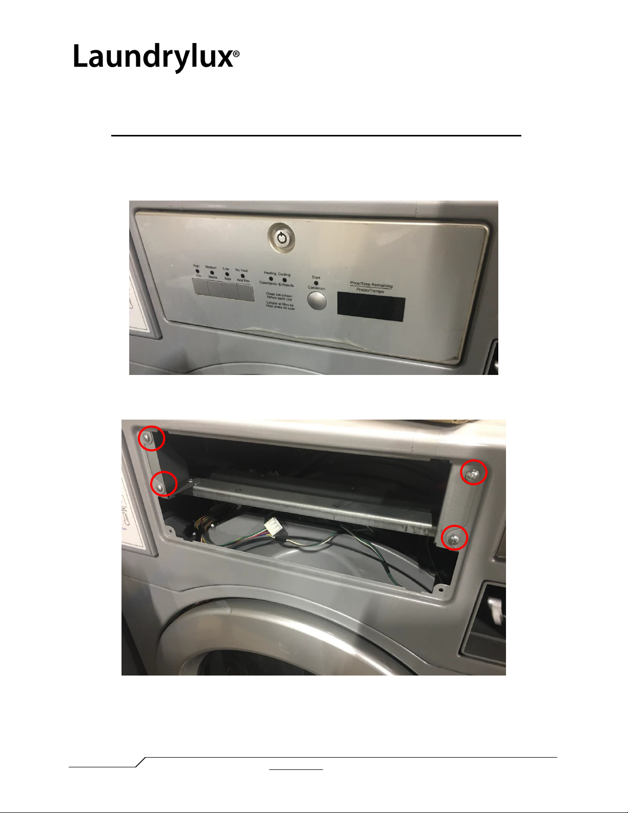
1. Demount the top control dryer (DLHF) control panel by using the provided service key.
Before disconnecting the harnesses mark each connector pair for reconnection later.
2. Remove the front control panel frame by removing the four screws shown.

Technical Information: TI 1146A
LAUNDRYLUX
www.laundrylux.com
461 DOUGHTY BLVD, INWOOD, NY 11096-0338 TELEPHONE: 516-371-4400
PARTS AND SERVICE Parts: 516-371-2000 Service: 516-371-0700 Fax (US & Canada): 516-371-4029 e-mail: [email protected]
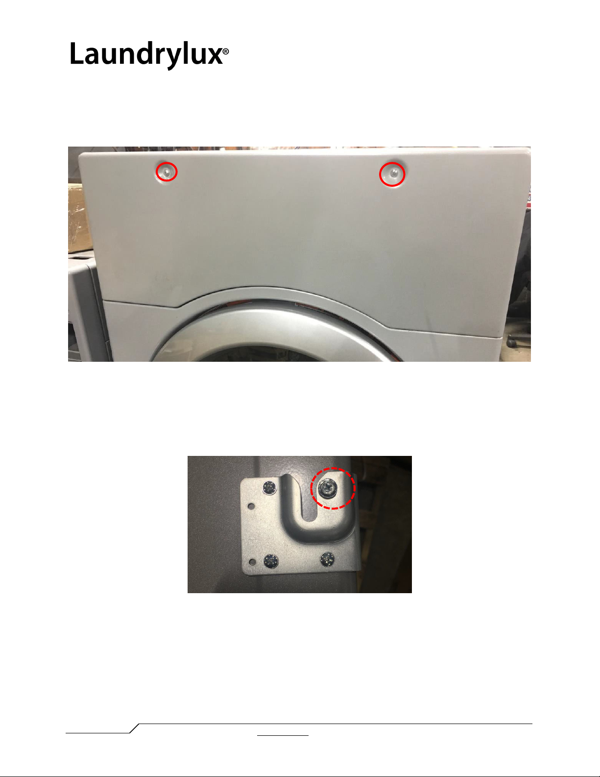
3. Remove 2 screws from the front of the top panel as shown.
4. Remove the 2 top panel-securing screws located at the back of the panel.
5. Slide the top cover panel forwards and then up to remove the top cover panel from the
machine.
Technical Information: TI 1146A
LAUNDRYLUX
www.laundrylux.com
461 DOUGHTY BLVD, INWOOD, NY 11096-0338 TELEPHONE: 516-371-4400
PARTS AND SERVICE Parts: 516-371-2000 Service: 516-371-0700 Fax (US & Canada): 516-371-4029 e-mail: [email protected]
6. Next remove the top-front panel of the bottom-control machine (DLHS) by removing the
2 screws from the top-front panel and demount it. Remove the top cover as previously
described.
7. Swap the panels from Top Control Machine to the Bottom Control Machine.
8. Remove the hex head extruded screw, attached on the front right stacking bracket and
save it for later use (Step 14)
9. After swapping the top panels, “gently” lay the bottom control dryer (DLHS) on one side
exposing the underside of the dryer. Make sure to cover the floor underneath the dryer
with foam pads so the side panels are not damaged.
Technical Information: TI 1146A
LAUNDRYLUX
www.laundrylux.com
461 DOUGHTY BLVD, INWOOD, NY 11096-0338 TELEPHONE: 516-371-4400
PARTS AND SERVICE Parts: 516-371-2000 Service: 516-371-0700 Fax (US & Canada): 516-371-4029 e-mail: [email protected]
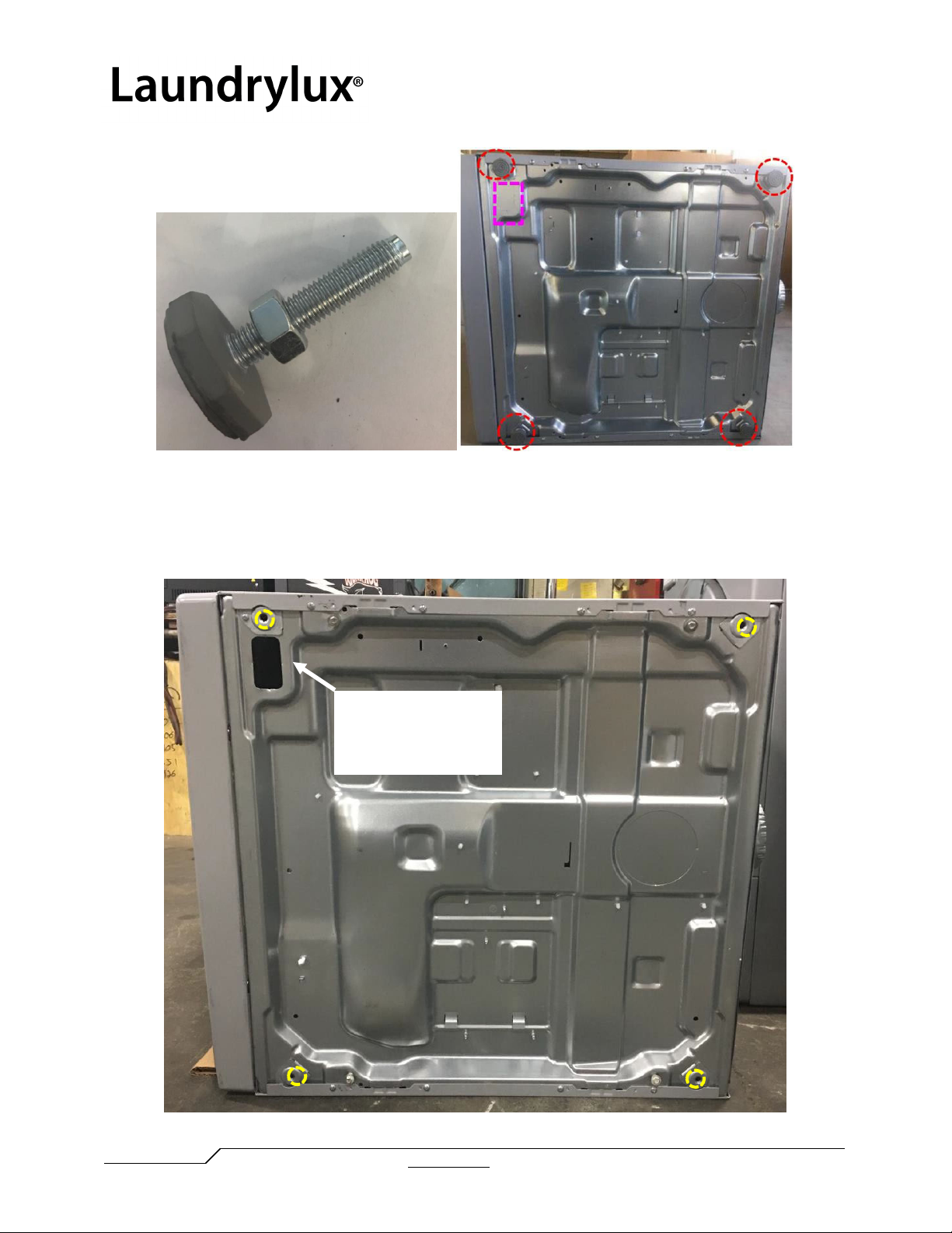
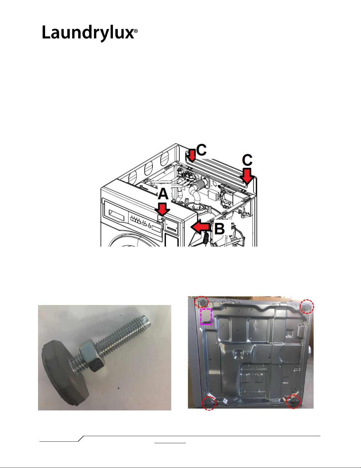
10. Remove the four adjustable feet from the dryer and remove the rectangular “knockout”
plate as indicated in the picture. Loosen slightly, but do not remove, the 4 shouldered self-
extrusion screws which are already attached under the base panel of the DLHS dryer.
Remove
rectangular
knockout

Technical Information: TI 1146A
LAUNDRYLUX
www.laundrylux.com
461 DOUGHTY BLVD, INWOOD, NY 11096-0338 TELEPHONE: 516-371-4400
PARTS AND SERVICE Parts: 516-371-2000 Service: 516-371-0700 Fax (US & Canada): 516-371-4029 e-mail: [email protected]
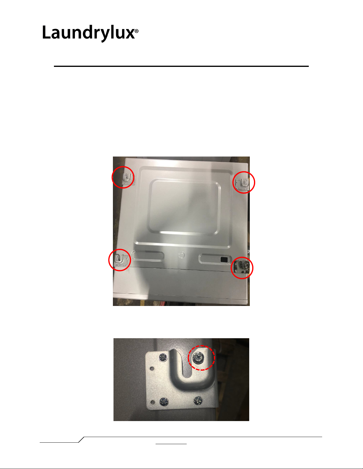
11. Stack the bottom-control machine (DLHS) on top of the top-control (DLHF) machine.
The four self-extrusion step screws in the underside of must slide through the stacking
bracket slots. Position the dryer so the front panels of both machines are aligned.
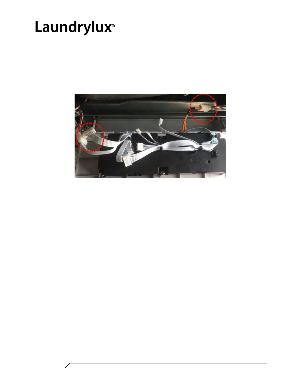
12. Once the machines are securely stacked, open the control panel of the bottom control
machine DLHS using the provided service key. As before mark each harness connector
pair before disconnecting the harnesses to aid in reconnection.
Technical Information: TI 1146A
LAUNDRYLUX
www.laundrylux.com
461 DOUGHTY BLVD, INWOOD, NY 11096-0338 TELEPHONE: 516-371-4400
PARTS AND SERVICE Parts: 516-371-2000 Service: 516-371-0700 Fax (US & Canada): 516-371-4029 e-mail: [email protected]
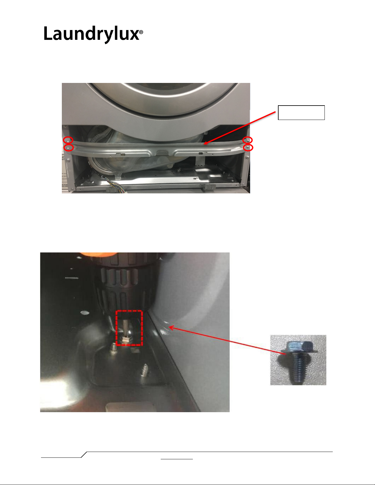
13. Remove the control panel frame and demount the horizontal bar that runs from the left
to the right side by removing the 4 mounting screws.
14. Feed the hex head screw previously removed in step #8 through the base of the upper
machine and feed back into the threaded hole in FRONT-RIGHT mounting bracket of the
lower machine using a socket ratchet, locking the position of the two machines relative to
each. WARNING: This step must be done correctly to prevent the upper machine from
being pushed backwards. Note: for COIN metered machines see step 16.
15. Reattach the cross bar and panel frame but do not remount the control panel.
Cross bar
Technical Information: TI 1146A
LAUNDRYLUX
www.laundrylux.com
461 DOUGHTY BLVD, INWOOD, NY 11096-0338 TELEPHONE: 516-371-4400
PARTS AND SERVICE Parts: 516-371-2000 Service: 516-371-0700 Fax (US & Canada): 516-371-4029 e-mail: [email protected]
16. For metered connections, feed the DLHS extension harness through the knockout
plate and connect the COIN1 harness plug to the coin meter in the lower machine as
indicated by the coin meter faceplate arrow.
17. Before remounting the control panel, reconnect the harness connections and lock the
controller using the service key.
Technical Information: TI 1146A
LAUNDRYLUX
www.laundrylux.com
461 DOUGHTY BLVD, INWOOD, NY 11096-0338 TELEPHONE: 516-371-4400
PARTS AND SERVICE Parts: 516-371-2000 Service: 516-371-0700 Fax (US & Canada): 516-371-4029 e-mail: [email protected]
DLHS over WHLFP (Dryer-Washer) Stacking Instructions
NOTE: It is recommend that the function check specified in the washer’s installation
manual be carried out before mounting the dryer on top remembering to disconnect the
power after the check is completed.
1. The washer’s replacement top panel for dryer mounting (part # 0020809423F) does not
come with the stacking bracket hardware attached. This hardware is recycled from the
DLHS dryer. The panel has a total of 12 tapped holes, 3 in each corner for attaching the
stacking brackets hardware. Demount the stacking brackets attached to the top panel of
the DLHS dryer and mount them on the washer’s replacement top panel.
2. Remove the hex head extruded screw, attached on the front-right stacking bracket and
save it for later use (Step 10)
Technical Information: TI 1146A
LAUNDRYLUX
www.laundrylux.com
461 DOUGHTY BLVD, INWOOD, NY 11096-0338 TELEPHONE: 516-371-4400
PARTS AND SERVICE Parts: 516-371-2000 Service: 516-371-0700 Fax (US & Canada): 516-371-4029 e-mail: [email protected]
3. Remove the top cover panel from the washer by:
a) Unlocking the coin meter bracket (A);
b) Removing the hex head security bolt located in the rear of the payment area (B);
c) Removing the 2 top cover-securing Philips screws located at the back of the cover
(C) and;
d) Sliding the cover back and up to demount the top cover.
Replace the original washer top panel with the washer’s prepared replacement top panel.
Remount the two screws and security bolt. Set aside the washer’s original top panel if
possible future reconversion to stand alone use is desired.
4. “Gently” lay the bottom control dryer (DLHS) on one side exposing the underside of the
dryer. Make sure to cover the floor underneath the dryer with foam pads so the side panels
are not damaged.
This manual suits for next models
1
Other Laundrylux Dryer manuals


Popular Dryer manuals by other brands


ffuuss
ffuuss eos user manual

KitchenAid
KitchenAid 53-3498 installation instructions

Schulthess
Schulthess Spirit topLine TW 8340 operating instructions

Whirlpool
Whirlpool LGR4624BW0 parts list

World Dryer
World Dryer AirMax D M5-972A manual

Alliance Laundry Systems
Alliance Laundry Systems ADEE9BSS user guide


