Lauper Instruments LIPPKE 2000 SL User manual

User Manual
Package Test System
LIPPKE 2000 SL
Gas-Detection
www.lauper-instruments.ch
Lauper Instruments AG
Irisweg 16B
CH-3280 Murten
Tel. +4126 672 30 50
www.lauper-instruments.ch

Package test system LIPPKE 2000 SL Introduction
Paul Lippke Handels-GmbH 2
Contents
1 Safety instructions 5 - 6
2 Introduction 7 - 11
2.1 System survey 7 -9
2.1.1 The LIPPKE 2000 SL control unit 7
2.1.2 Holding stand and needle heads 8 - 9
2.1.3 Clamping device 9
2.2 General operating instructions 10 - 11
3 Commissioning 12 - 16
3.1 Conditions 12 - 13
3.1.1 Electrical supply 12
3.1.2 Environment 12
3.1.3 Compressed air supply 13
3.2 Installation 13 - 16
3.2.1 Electrical connections 13
3.2.2 Mechanical construction of holding stand 14 - 15
3.2.3 Pneumatic connections 15
3.3 Operation 16
4 Burst test 17 - 20
4.1 General instructions for burst test 17 - 19
4.1.1 Safety instruction 17
4.1.2 Standard settings 17
4.1.3 Instructions for clamping device 17
4.1.4 Instructions for holding stand 17 - 18
4.1.5 Measurement 18
4.1.6 After the measurement 19
4.2 Activation of burst test 19
4.3 Carrying out the measurement 19
4.4 Parameter settings 19
4.5 Protocol 19 - 20

Package test system LIPPKE 2000 SL Introduction
Paul Lippke Handels-GmbH 3
5 Pressure loss test 21 - 25
5.1 General instructions for pressure loss test 21 - 22
5.1.1 Safety instruction 21
5.1.2 Standard settings 21
5.1.3 Instructions for clamping device 21
5.1.4 Instructions for holding stand 21 - 22
5.1.5 Measurement 22
5.1.6 After the measurement 22
5.2 Activation of pressure loss test 23
5.3 Carrying out the measurement 23
5.4 Parameter settings 24
5.5 Protocol 24 - 25
6 Configuration 26 - 37
6.1 Number of print-outs 26 - 27
6.2 Auto-Stop-threshold 27
6.3 Compensation time 27
6.4 Interface output 27 - 34
6.5 Printer configuration 35 - 36
6.6 Date and time 36
6.7 Acoustic signal 37
6.8 Pressure unit 37
7 Maintenance 38
8 Error causes 39 - 40
8.1 System errors 39
8.2 Interface errors 39
8.3 Problems during measurements 40
9 Appendix 41 - 44
9.1 Operating principles 41 - 42
9.2 Specifications and certificate 42 - 43
9.3 Dimensions and weights 44
9.4 Spare parts list 44

Package test system LIPPKE 2000 SL Introduction
Paul Lippke Handels-GmbH 4
Index of figures
Figure 2.1: Package test system 7
Figure 2.2: Holding device 8
Figure 2.3: Needle No. 1B 8
Figure 2.4: Needle No. 2B 9
Figure 2.5: Needle No. 3B 9
Figure 2.6: Clamping device 9
Figure 2.7: Control unit, front panel 10
Figure 3.1: Holding stand 14
Figure 3.2: Construction of filter 15
Figure 3.3: Control unit, rear panel 15
Figure 4.1: Print-out of a burst test 20
Figure 5.1: Print-out of a regular pressure loss test 25
Figure 5.2: Print-out of a pressure loss tests with bursting of package 25
Figure 6.1: Test report, burst test 28
Figure 6.2: Test report, pressure loss test 29
Figure 6.3: Data output at the end of burst test 30
Figure 6.4: Data output at the end of pressure loss test 31
Figure 6.5: Data output, burst test 32
Figure 6.6: Data output, pressure loss test 33/34
Figure 9.1: Pneumatic system 41
Figure 9.2: Sample of works certificate 43
Index of tables
Table 3.1: Environmental conditions 12
Table 3.2: Assignment of connections: Holding and clamping device 16
Table 6.1: Cutting signal 35
Table 8.1: System errors 39
Table 8.2: Interface errors 39
Table 9.1: Dimensions and weights 44
Table 9.2: Spare parts list 44

Package test system LIPPKE 2000SL Safety instructions
Paul Lippke Handels-GmbH 5
1 Safety instructions
•
This operator’s manual has to be read, understood and observed before commissioning the
test system.
•
If one of the following safety instructions is not or only partially observed, the Paul Lippke
Handels-GmbH can assume no responsibility for any consequential damages, defects or the
reliability of the test system.
•
We proceed on the assumption that the operator will use this test system carefully and
sensibly.
•
You must not continue system operation if any system malfunctions occur.
•
The test system must not be modified with regard to its construction and design without
prior consultation of the manufacturer.
•
This operator’s manual must be enclosed if the test system is resold.
•
Please make sure that the test system is only connected to the mains power supply men-
tioned on the nameplate.
•
Please also make sure that the connection pressure of compressed air supply does not ex-
ceed the maximum pressure.
•
Please provide sufficient air circulation and install the test system in a sufficient distance
to other objects.
•
Never clean the test system with any liquids if it is connected to the mains socket-outlet.
•
Disconnect the test system from the mains line and remove the compressed air supply be-
fore opening its front or rear panel.
•
Maintenance works which are possibly required may only be performed by the customer
service department of the Lippke company.

Package test system LIPPKE 2000SL Safety instructions
Paul Lippke Handels-GmbH 6
•
The following symbols are used in order to obtain more clarity:
•
Caution: Please observe instruction by all means.
•
•
Important note, may lead to malfunctions or damage of test system if
•
not observed
•
•
Note, which is helpful in operating and using the test system.

Package test system LIPPKE 2000 SL Introduction
Paul Lippke Handels-GmbH 7
2 Introduction
2.1 System survey
The system LIPPKE 2000 SL (see figure 2.1) developed by the Paul Lippke Handels-GmbH
offers the user the option to test packages with regard to their impermeability and sealing seam
stability (burst test = BURST mode) and to their tightness (pressure test = LOSS mode).
In the burst test a linear pressure rise is created in the package until the package bursts. Thus the
burst pressure is a measure for the impermeability of the seams of the package.
For measuring the tightness of a package, first a pressure is built up inside the package. There will
be a pressure loss in the package during test time if the tested package is leaky. This pressure loss
is measured and displayed.
Figure 2.1: Package test system LIPPKE 2000 SL
The serial interface permits the output of test reports to a printer or PC.
2.1.1 The LIPPKE 2000 SL control unit
The LIPPKE 2000 SL control unit houses the micro controller and the pneumatic system. Here
the air supply is connected and guided through the package holding device to the package in a
controlled way. Operation and display take place via the front panel.
In general, the test result is displayed on the digital display. However, the use of a serial interface
is recommended for optimum documentation and for outputs on a printer. It is also possible to
link the system to a PC (e.g. via the ”Terminal Program” by WINDOWS
). Apart from this
result, all test parameters as well as date and time are transmitted. A corresponding printer can be
purchased via LIPPKE.

Package test system LIPPKE 2000 SL Introduction
Paul Lippke Handels-GmbH 8
2.1.2 Holding stand and needle heads
A closed package is connected to the control unit by means of the package holding stand (see
figure 2.2).
Figure 2.2: Package holding stand
Two different types of needle heads are used in order to conduct compressed air into the package:
the mono needles (type 1B and type 2B) and the double needle type 3B.
Mono needles are suitable for almost all packages. There is no danger of measuring needle clog-
ging by the product, since here only one needle is used for air supply and pressure measurement.
Pricking into the package is made easier by the needle type 1B (see figure 2.3). Nevertheless the
use of a needle type 2B (see figure 2.4) is recommended for flat packages in order avoid
undesired damage to the underside of the package.
Figure 2.3: Needle Type 1B

Package test system LIPPKE 2000 SL Introduction
Paul Lippke Handels-GmbH 9
Figure 2.4: Needle Type 2B
In case of the double needle (see figure 2.5), the sensor line is lead separately into the package. If
very large air supply is required for measuring, back-pressure is possible when using a mono
needle. This effect occurs above all with packages made of materials permeable to air, like sterile
paper, Tyvek etc. An O-ring inside the needle head provides the sealing of both air channels.
Figure 2.5: Needle Type 3B
2.1.3 Clamping device
A package open on one side is connected to the control unit by means of the clamping device (see
figure 2.6). The open end of the package is sealed almost airtight between the clamps. Only the
two connections for air supply and pressure measurement are lead to the control unit.
Figure 2.6: Clamping device

Package test system LIPPKE 2000 SL Introduction
Paul Lippke Handels-GmbH 10
2.2 General operating instructions
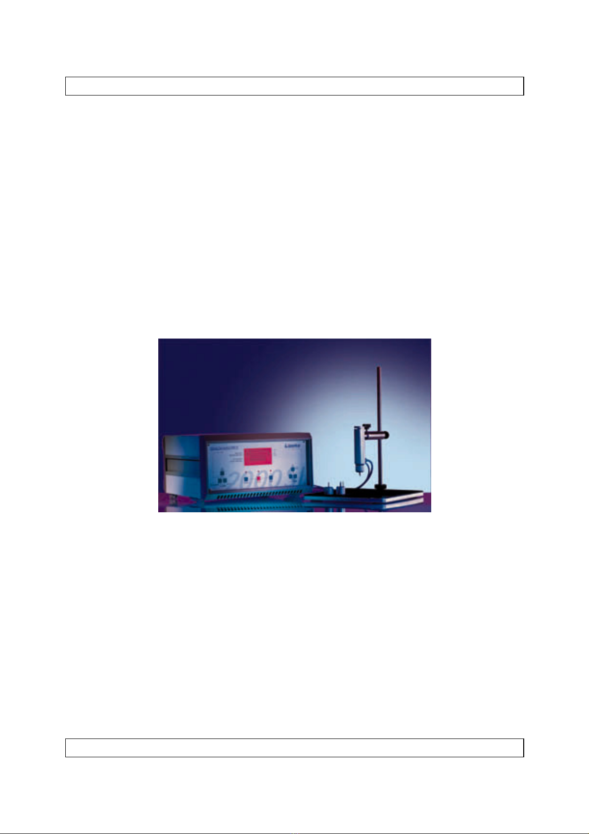
After switching on (power switch on the rear panel, see figure 3.3, page 16), the LIPPKE 2000 SL
control unit first displays the parameter last used (see figure 2.7).
Figure 2.7: Control unit, front panel
The two red LEDs on the left side of the display field indicate the active mode: The BURST
TEST LED indicates a burst test and the PRESSURE LOSS TEST LED indicates a pressure loss
test. Depending on the four LEDS on the right side, the digital display has different meanings:
“mbar”: The current pressure is displayed in ”mbar”, if this LED lights up, otherwise in
”PSI”
“∆P” signalises pressure loss in ”mbar” or ”PSI” (see above)
With ”SEC”, test time is indicated in seconds and with
”MIN” in minutes.
The LED bar display below the numerical display field has the following meaning:
Burst test: The current internal pressure inside the package is displayed in the overall
range of 0 - 3000 mbar on the ”ACTUAL PRESSURE” display. Thus one
LED corresponds to 300 mbar.
Pressure loss test: The selected test pressure is displayed on the ”SET PRESSURE” display.
All 10 LEDS always light up. The current internal pressure of the package
is displayed on the ”ACTUAL PRESSURE” display. One LED is
extinguished for each pressure loss of 10%.
Setting of mode and pressure is performed in the left part of the operator panel. The ”TEST
MODE” key serves for changing to the desired mode. The function is activated by pressing the
”+”- or ”-” key, i.e. a pressure value or a pressure rise rate is displayed on the display. Then the
pressure can be set by means of the ”+”- and ”-” key. The values are changing the faster the
longer the key is pressed. In test system configuration (see chapter 6), you can determine whether
the factory-set default pressure unit ”mbar” shall be changed into the pressure unit ”PSI”.

Package test system LIPPKE 2000 SL Introduction
Paul Lippke Handels-GmbH 11
Setting of test time (only in LOSS Mode!) is performed on the right panel. The function is acti-
vated by pressing one of these three key, i.e. a time value is now displayed. ”SEC MIN” serves
for changing to the desired unit of time (seconds or minutes). Test time can be set by means of the
”+”- and “”-” key. The values are changing the faster the longer the key is pressed.
If you press ”TIME” during a test, the elapsed time (burst test) or the remaining test time
(pressure loss test) is displayed.
Your system has the standard configuration at the time of delivery. You will find further
operating instructions in chapter 6 ”Configuration”, from page 26 on.

Package test system LIPPKE 2000 SL Commissioning
Paul Lippke Handels-GmbH 12
3 Commissioning
3.1 Conditions
3.1.1. Electrical supply
Important note: Connection to a mains power supply unit different from the
nameplate can lead to device damage.
A mains power supply of 230 V∼± 10 % at a frequency of 50 Hz ± 1 Hz is required for the sys-
tem (other options upon request). Please note that the above-mentioned conditions are not always
kept in direct vicinity of large electrical machines. Wherever necessary and in case of doubt, a
mains filter must be connected in series. In case of power failures, the current test may be inter-
rupted.
3.1.2. Environment
Important note: Operating the test system outside the above-mentioned limits
may lead to malfunctions and device damage.
Never install the system close to heat sources. It must be protected from direct sunlight, heavy
dust contamination, vibrations, liquids and extreme air humidity. If any liquid is accidentally
introduced into the control unit, have the system checked by Lippke before continuing the
operation. It is important to observe the following limits:
Condition Limits
Ambient temperature + 5 ... 40
0
C
Air humidity 0 ... 90% relative humidity
without condensation
Table 3.1: Environmental conditions

Package test system LIPPKE 2000 SL Commissioning
Paul Lippke Handels-GmbH 13
3.1.3. Compressed air supply
Caution: If it is not ensured that maximum pressure is kept in any case, there is
danger of bursting of hoses and other parts.
Important note: Perfect function is not guaranteed if the pressure value remains
under the above-mentioned input pressure.
Compressed air should be dry, clean and free from oil and be supplied with an input pressure of 4
... 7 bar (at least 1 bar above measurement pressure) (please use adequate pressure reducer). We
recommend a compressed air quality according to ISO standard 343. If air quality is not suffi-
ciently known, it is recommended to process the air by means of a filter combination (5µ and
0,01µ) and by a end position drier with regenerative cartridge (e.g. Zander Min-DRY MDK and
KT 2016) connected in series. The possible expenditure for this cleaning effects exact measuring
results and trouble-free long-time operation of the entire pneumatic system. Air consumption
basically depends on size, stability and porosity of packages and number of measurements.
3.2 Installation
Important note: Please read the following notes by all means before
beginning installation.:
First check all devices and systems for possible transportation damage and immediately assert
warranty claims, should the occasion arise.
3.2.1. Electrical connections
All connections are arranged on the rear panel of the LIPPKE 2000SL control unit (see figure 3.3,
page 16). First connect the mains power cable (connection ”230V~ MAINS”). After that, you
may connect the optional connecting cable (nine-pole interface cable) to the output unit (printer,
PC). For this purpose, use the port marked with ”RS 232”.

Package test system LIPPKE 2000 SL Commissioning
Paul Lippke Handels-GmbH 14
3.2.2. Mechanical construction of holding stand
In general, the package holding stand is delivered already completely assembled, so that you don’t
have to read this chapter.
Assembly according to 3.1 only requires a few movements of the hand. The bar must be screwed
into the base plate. Then you have to tighten the lock ring. An arm with height and angle adjust-
ment, which must be attached next, if necessary, is optionally available for smaller sized
packages. Now the flexible holding arm for the test head can be mounted.
Figure 3.1: Package holding device
The needle head can be screwed onto the test head. This connection is sealed with an O-ring.
If you use packages filled with pulverised or liquid substances, you must insert the optionally
available filter between test head and needle head (see figure 3.2).

Package test system LIPPKE 2000 SL Commissioning
Paul Lippke Handels-GmbH 15
O-Ring
O-Ring
Filterschaum-
stoff
Filtereinsatz Filterröhrchen
Prüfkopf Filter Nadelkopf
Figure 3.2: Construction of filter
First screw the filter element with foam filter into the test head for this purpose. Then the small
filter tube and the needle head can be attached. For the positions of the individual O-rings please
see figure 3.2.
3.2.3. Pneumatic connections
The pneumatic connections are also on the rear panel of the module (s. figure 3.3).
Paul Lippke Handels GmbH
230V~
MAINS
RS 232 FUSE 1A
AIR
SUPPLY FEED
SENSE
Figure 3.3: EPS module, rear panel
Connect the compressed air supply unit to “AIR SUPPLY”.
Fuse
Power Switch
RS 232
Feed
Sense
Air Supply

Package test system LIPPKE 2000 SL Commissioning
Paul Lippke Handels-GmbH 16
The connections for holding stand and clamping device are also on the rear panel of this module.
For the assignment of connections, see the following table:
Table 3.2: Assignment of connections, holding device and clamping device
Important note: Please make sure that all hoses are firmly and tightly connected.
Please use the union nuts delivered with the test system in any case for protecting
and sealing the connections.
3.3 Operation
First switch on the output device (printer, PC, etc.) and then the control unit LIPPKE 2000SL
(power switch on the rear panel). Now the LED ”STOP” lights up. Moreover, the parameters last
used are displayed: burst or pressure loss test and pressure rise rate or test pressure in mbar. Test
time and selected unit of time are displayed by pressing of one of the keys in the ”TIME” field
(“SEC MIN” or ”-”, ”+”)
Control unit
Holding device
Clamping device
Connection
Mark
C
onnection
Mark
SENSE
thin hose
no
thin hose
no
FEED
thick hose
no
thick hose
no

Package test system LIPPKE 2000 SL Burst test
Paul Lippke Handels-GmbH 17
4 Burst test
4.1 General instructions for burst test (LOSS mode)
The general information about burst tests is presented in brief outlines and sorted in the order
valid for carrying out a measurement procedure. This will facilitate subsequent retrieving of
special information during operation.
4.1.1. Safety instructions
Caution: In a burst test, the package will in general burst. This may lead to consid-
erable noise. Thus wear suitable hearing protection.
Important note: In case of filled packages you must further make sure that the
product doesn’t soil users or system, if possible. Depending on the package con-
tents we recommend to wear safety glasses. A silencing protective hood placed
over the package holding device offers perfect protection.
4.1.2 Standard settings
In most cases, each package type will require its own special measuring conditions. A standard
pressure rise rate is 5 mbar/s. In rare cases, further parameters may be matched (see chapter 6,
page 26).
4.1.3. Instructions for clamping device
The clamping device for packages open on one side can only be used in the burst test mode.
Fix the package between the clamps, if possible in the middle. Make sure that the nozzle, with the
openings for air supply and pressure measurement, is clamped into the package opening. When
testing extremely hard and stable packages it is possible that the package comes loose from the
clamping device. Increase the clamping pressure in this case by screwing the clamping pins
further out. If this is not sufficient, glue a strip of emery cloth on the sponge rubber gibs of the
clamping device, at the top and bottom.
4.1.4. Instructions for holding device
In order to ensure a linear pressure increase in the package and to avoid unnecessarily high con-
sumption of air it may be required to seal the prick-in point with a diaphragm. Additionally, this
diaphragm protects the packing material from tearing at the prick-in point. When testing flat
packages, the black diaphragm is recommended. Due to the thickness of the rubber material (3
mm), the flat needle head type 1B can be utilised. This needle head already provides good sealing
without penetration of the needle tip into the inside of the package.

Package test system LIPPKE 2000 SL Burst test
Paul Lippke Handels-GmbH 18
For small-sized packages which will deform under pressure also in the area of the sealing dia-
phragm, you should use the grey diaphragm ( 1mm thin and very flexible).
However, when performing burst tests it is not necessary in many cases to seal the package with a
diaphragm at the prick-in point. But if too much air comes out during measurement, a diaphragm
(with glueing side to the needle) or an O-ring around the needle tip can already be helpful.
Glueing spots and seams are less suitable for prick-in. Pricking in should be in the middle of the
package, if possible, in order to ensure that the package will blow up steadily. This is important,
because the needle must lie evenly and tightly on the package. The test head will be lifted due to
the volume enlargement, but this will be compensated by flexible guiding of the test head.
Testing flat packages: Here, there is the danger that the needle sticks through the package.
In this case it is safer to glue on a black diaphragm and to carefully prick the package with
a sharp object (e.g. needle no. 1 B). After that the use of the needle head no. 2 B is
recommended. The flattened and blunt tip of this needle remains sticking in the black dia-
phragm without penetrating into the package. Furthermore you have to make sure that the
package material was pierced through sufficiently in order to avoid too much pressure in
front of the package. As soon as the package has blown up so much that there is no more
danger of damage to the underside of the package, you should pass the needle fully into
the package in order to ensure that the needle head surface lies evenly on the diaphragm.
Testing filled packages: It is important to avoid clogging of the needle with the product
during introduction. In any case the opening must remain free since otherwise pressure
measurement may be affected. When testing packages with liquid or pulverised contents
the filter must be mounted.
Testing small-sized packages: We recommend the use of the auxiliary arm (see figure 3.2,
page 16). Positioning may then be carried out easier and faster.
4.1.5. Measurement
It is important to watch the package carefully during measurement. If you hear air coming out,
you have to seal, if necessary (see above).
Furthermore, valuable information can be gained during measurement, like for example:
•Does the sealing seam open slowly before the package bursts?
•The leaky point is signalised by bubbles when the package is tested submersed in a liquid
•Where does the package burst ? So where is the weak point ?

Package test system LIPPKE 2000 SL Burst test
Paul Lippke Handels-GmbH 19
4.1.6. After the measurement
Caution: If the package did not burst, it is still under pressure! Remove the pack-
age carefully, since pressure falls rather quickly through the prick-in point.
In case of package bursting, the burst pressure is displayed by the 2000 SL and you can take out
the package.
4.2 Activation of burst test
The burst test is activated (if necessary, switch mode by ”TEST-MODE”), as soon as the LED
”BURST-TEST” lights up. After that, all you have to do is starting the measurement by
”START”.
4.3 Carrying out the measurement
You may start the measurement by pressing the ”START” key. After that, pressure is increased
linearly with the selected pressure rise rate. Below the digital value, the current pressure is also
displayed on the bar display. If the package did burst, burst pressure is displayed and a print-out is
output (see chapter 4.5).
A test can be interrupted at any time by pressing the ”STOP” key. (If this key is pressed for two
seconds, there will be no print-out.)
At the end of the test, the ”STOP” LED lights up.
4.4 Parameter settings
Apart from the test mode, the pressure rise rate must be set.
It may be set with the following graduation: 5, 10, 20, 30, 40, 50, 70, 80, 90 and 100 mbar/s.
4.5 Protocol
In case of package bursting, the data of this test will be output on the serial interface (e.g. to a
printer). You can read details about formatting this output in chapter 6, page 26. The standard
type of data output at the end of the test is shown on the following page:

Package test system LIPPKE 2000 SL Burst test
Paul Lippke Handels-GmbH 20
PACKAGE TEST SYSTEM
LIPPKE 2000 SL
Date: 28.08.98
Time: 22:51
Mode: Burst test
Product:
Batch:
Tester:
Remark:
Pressure rise rate: 10 mbar/s
Burst pressure: 265 mbar
Figure 4.1: Print-out of a burst test
You can now enter product, batch, tester and a remark if necessary.
Table of contents
Other Lauper Instruments Test Equipment manuals
Popular Test Equipment manuals by other brands

Hickok
Hickok AUTO WAVE II user guide

Tektronix
Tektronix MSO70000C Series user manual

Symmetricom
Symmetricom TimeHub 5500 reference guide

Agilent Technologies
Agilent Technologies 1000B Series user guide

Tecnogas
Tecnogas 11621 Operation manual

Agilent Technologies
Agilent Technologies 16034G Operation manual