manuals.online logo
Brands
  1. Home
  2. •
  3. Brands
  4. •
  5. RDA
  6. •
  7. Test Equipment
  8. •
  9. RDA HC3 User manual

RDA HC3 User manual

Refrigerant Recovery - Pass Through Method
This method of recovery uses the unit to pull the refrigerant from the plant and
discharge it direct to a suitable recovery cylinder. This method is best suited to
applications where up to 3kg of refrigerant is to be recovered.
Use a manifold gauge set to connect to both high and low sides of the plant. If
possible connect to the plant on the high side at a point where the refrigerant
will be in liquid form. Connect the centre hose to the unit inlet.
Connect the discharge of the unit to a suitable recovery cylinder. Ensure that
the recovery cylinder has sufficient free volume to accept the refrigerant you
are going to recover and is monitored by a weigh scale. Zero (Tare) the scale
Open the valves at the plant and cylinder.
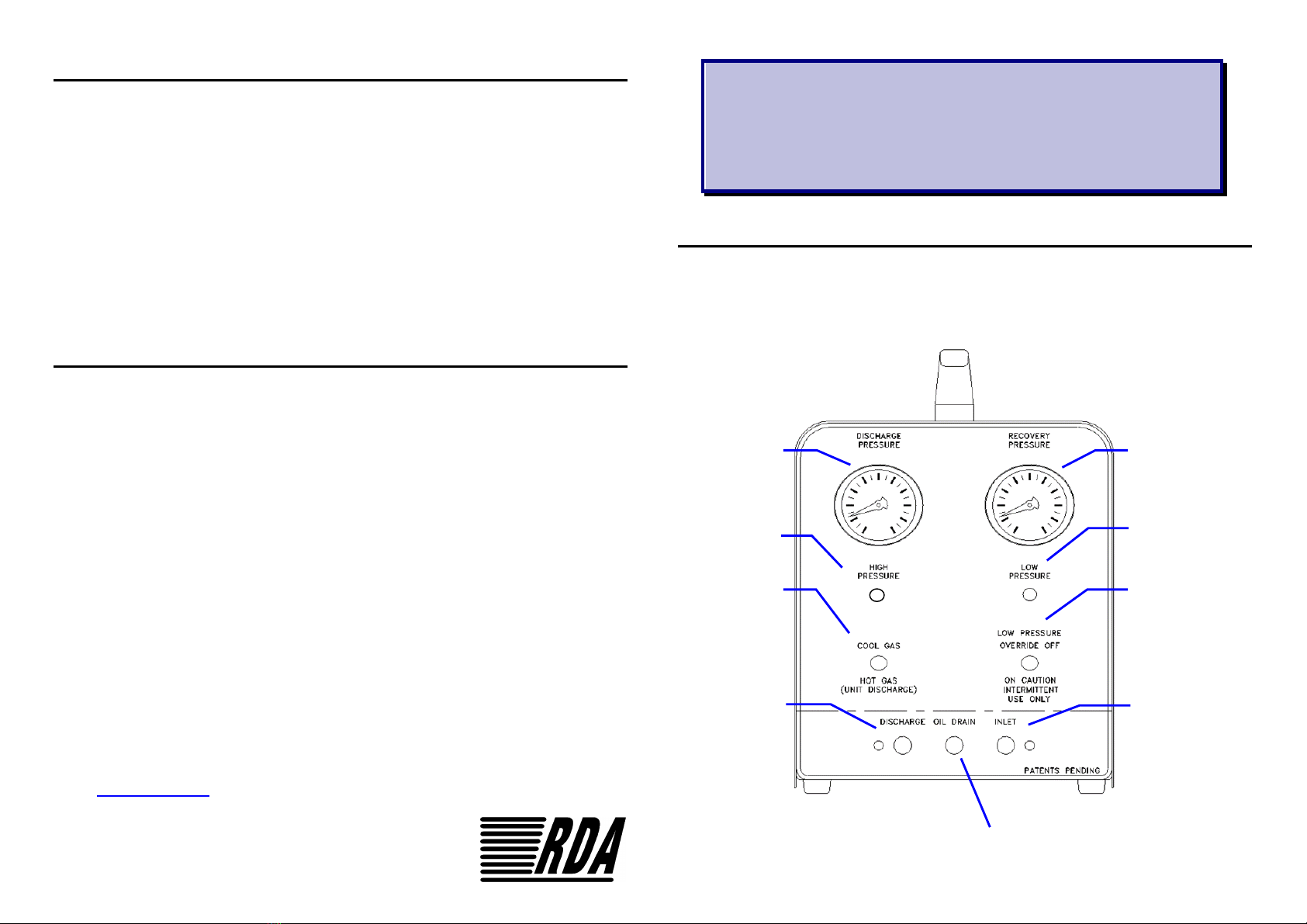
Set the selector switch to Coolgas.
Switch the Unit ON at the mains socket.
The unit will start to recover refrigerant. You will hear the HC-3 click as it recovers
refrigerant. When the entire liquid refrigerant has been recovered the clicking will
stop and the pressure on the unit gauge will begin to fall. When the inlet pressure
reaches 0 bar the unit compressor will automatically stop.
Close the inlet hose valve and operate the LP override ON and allow the unit to
run for 1 minute maximum to complete the recovery.
Switch the unit OFF at the mains socket and close all valves and disconnect
hoses.
Record the mass of refrigerant recovered.
Refrigerant Recovery - Push - Pull Method
This method of recovery uses the unit to pressurize the refrigerant in the plant so that it can be
discharged directly to a suitable recovery cylinder. This method is best suited to applications where
more than 3kg of refrigerant is to be recovered.
Connect the inlet connection of the unit to the vapour port of a suitable twin ported recovery
cylinder.
Connect the discharge of the unit to a suitable point on the plant where the refrigerant will be in
vapour form.
Connect a hose from a liquid port on the plant to the liquid connection on the recovery cylinder.
Ensure that the recovery cylinder has sufficient free volume to accept the refrigerant you are going
to recover and is monitored by a weigh scale. Zero (Tare) the scale
Open the valves at the plant and cylinder.and switch the unit On at the mains socket.
Set the selector switch to Hotgas.
The unit will start to recover refrigerant from the cylinder, which will reduce the pressure within the
cylinder. At the same time the unit will discharge into the plant which will raise the pressure. The
pressure difference between the plant and the cylinder will result in refrigerant transfer. You will hear
the HC-3 click as it recovers refrigerant.
When the bulk of the refrigerant has been recovered, reconfigure the set up to the
Pass Through method to remove the remaining refrigerant vapour. When the inlet
pressure reaches 0 bar the unit compressor will automatically stop.
Close the inlet hose valve and operate the LP override ON and allow the unit to run for 1 minute
maximum to complete the recovery. Switch the unit OFF at the mains socket.
Close all valves, disconnect hoses.and record the mass of refrigerant recovered.
Hints and Tips
To provide maximum protection to the unit it is recommended to fit a filter in the suction
hose during operation. Using hoses with integral shut off valves will enable the unit to be
disconnected from the cylinder without venting the contents of the hose to atmosphere.
It is recommended that the valve depressors are removed from hoses if not required.
*Vacuum certified valve core removal tools are available for connection to the plant.
Heat Exchanger/Oil Separator - The unit uses a combined heat exchanger/oil separator
during the recovery process. Oil from recovered liquid should periodically be drained,
with the unit switched off, via the removable cap situated on the front of the unit.
It will be necessary to discharge the residual refrigerant between jobs, to avoid any mixing.
Connect the discharge to a recovery cylinder and set the selector switch to Hotgas/Self
discharge. Set the LP override switch ON and briefly run the unit.
Safety Notes
Every effort has been made to make the unit as easy and safe to operate as possible but
operators should always follow these safety precautions.
Always wear appropriate eye protection, clothing and gloves when handling
refrigerant.
Only a trained operator should handle refrigerants. Engineers working with HC
refrigerants should be trained specifically to EN378-4:2016 +A1:2019 Annex E.
Never overfill a cylinder. * Weigh the recovery cylinder and fill to only 60% of the
volume with liquid to leave room for expansion.
If a compressor burn-out is suspected on the appliance carry out a refrigerant test
for acid. If recovery is still to be undertaken fit a burn out filter in the hose line
during recovery.
Make sure that the plant is switched off before attempting to recover refrigerant.
Do not leave the unit unattended whilst recovery is in progress.
When recovering HC refrigerants the area must be well ventilated. We recommend
the *HC-AIR Fan module with ATEX motor. There must be no ignition source
within 3m of the work and the area must be monitored with a hydrocarbon
detector.
NB: Improper use of this equipment will invalidate the warranty
*Visit www.rda-eng.com for details of accessories
HC3
Instruction Manual
Introduction Iss. 2
The HC3 Hydrocarbon Refrigerant Recovery Units are designed as compact, easy
to use service tools. The units will remove hydrocarbon refrigerants in liquid or
vapour state from the plant direct to a suitable recovery cylinder.
RDA Environmental Engineering Limited
Riverway Industrial Estate, Newport, Isle of Wight, PO30 5UX
Tel: 01983 821189 Email: tech@rda-eng.com
Environmental Engineering
Discharge
Pressure
Gauge
Recovery
Pressure
Gauge
High
Pressure
Indicator
Low Pressure
Indicator
Cool /Hot
Gas (Self
Discharge)
Switch
Low Pressure
Override
Switch
Discharge
Connection Inlet
Connection
Oil Out
Connection

Popular Test Equipment manuals by other brands

Keller HPX operating instructions

Keller

Keller HPX operating instructions

Tektronix THDP0100 Installation and safety instructions

Tektronix

Tektronix THDP0100 Installation and safety instructions

ISA BTS200 MKII manual

ISA

ISA BTS200 MKII manual

STEP SYSTEMS ECO pH manual

STEP SYSTEMS

STEP SYSTEMS ECO pH manual

WattMaster AMM10 instruction manual

WattMaster

WattMaster AMM10 instruction manual

innovAg DairyTest Lite user manual

innovAg

innovAg DairyTest Lite user manual

norbar Pro-Test 60 SERIES 2 Operator's manual

norbar

norbar Pro-Test 60 SERIES 2 Operator's manual

SW Stahl PROFI Tools 26110L instruction manual

SW Stahl PROFI Tools

SW Stahl PROFI Tools 26110L instruction manual

elv SUP3 manual

elv

elv SUP3 manual

Tektronix MSO 4 Series Installation and safety

Tektronix

Tektronix MSO 4 Series Installation and safety

American DJ Dr. DMX User instructions

American DJ

American DJ Dr. DMX User instructions

Compliance West CDT-240 CALIBRATION PROCEDURE

Compliance West

Compliance West CDT-240 CALIBRATION PROCEDURE

Proceq PROFOSCOPE operating instructions

Proceq

Proceq PROFOSCOPE operating instructions

KPS DT30 instruction manual

KPS

KPS DT30 instruction manual

Klein Tools RT210 manual

Klein Tools

Klein Tools RT210 manual

PMK SMP Series manual

PMK

PMK SMP Series manual

Fluke Calibration 5322A Operator's manual

Fluke Calibration

Fluke Calibration 5322A Operator's manual

Lovibond MD 100 Additional features & benefits

Lovibond

Lovibond MD 100 Additional features & benefits

manuals.online logo
manuals.online logoBrands
  • About & Mission
  • Contact us
  • Privacy Policy
  • Terms and Conditions

Copyright 2025 Manuals.Online. All Rights Reserved.