SEFRAM 5322DC User manual

Digital Storage Oscilloscope
SEFRAM 5322DC, 5342DC, 5362DC, 5382DC
USER MANUAL
M53X2DC A 00

TABLE OF CONTENTS
3
Table of Contents
SAFETY INSTRUCTION.........................7
Safety Symbols................................................7
Safety Guidelines.............................................8
Power cord for the United Kingdom Erreur ! Signet non
défini.
GETTING STARTED ........................... 11
Main Features............................................... 11
Panel Overview ............................................. 12
Front Panel.................................................. 12
Rear Panel................................................... 15
Display ....................................................... 16
Setting up the Oscilloscope............................... 18
QUICK REFERENCE........................... 20
Menu Tree and Shortcuts.................................. 20
Acquire key.................................................. 20
Autoset key.................................................. 21
CH1/2 key ................................................... 21
Cursor key 1/2.............................................. 21
Cursor key 2/2.............................................. 22
Display key .................................................. 22
Hardcopy key ............................................... 23
Help key ..................................................... 23
Horizontal menu key....................................... 23
Math key 1/2................................................ 24
Math key 2/2................................................ 24
Measure key................................................. 25
Run/Stop key................................................ 25
Save/Recall key 1/9 ....................................... 26
Save/Recall key 2/9 ....................................... 26
Save/Recall key 3/9 ....................................... 27
Save/Recall key 4/9 ....................................... 27
Save/Recall key 5/9 ....................................... 28
Save/Recall key 6/9 ....................................... 28
Save/Recall key 7/9 ....................................... 29
Save/Recall key 8/9 ....................................... 29
Save/Recall key 9/9 ....................................... 30
Trigger key 1/4 ............................................. 30
User Manual – SEFRAM 53X2DC
4
Trigger key 2/4 ............................................. 31
Trigger key 3/4 ............................................. 31
Trigger key 4/4 ............................................. 32
Utility key 1/4 .............................................. 32
Utility key 2/4 .............................................. 33
Utility key 3/4 .............................................. 33
Utility key 4/4 .............................................. 33
Default Settings............................................. 34
Built-in Help................................................. 35
MEASUREMENT................................36
Basic Measurements........................................ 36
Activating a channel ....................................... 36
Using the Autoset .......................................... 37
Running and stopping the trigger........................ 38
Changing the horizontal position and scale ............ 39
Changing the vertical position and scale ............... 40
Using the probe compensation signal ................... 41
Automatic Measurements.................................. 43
Measurement items ........................................ 43
Automatically measuring the input signals............. 45
Cursor Measurements ...................................... 46
Using the horizontal cursors.............................. 46
Using the vertical cursors................................. 47
Math Operations ............................................ 48
Overview..................................................... 48
Adding or subtracting signals............................. 50
Using the FFT function .................................... 51
CONFIGURATION..............................52
Acquisition................................................... 52
Selecting the acquisition mode .......................... 52
Real time vs Equivalent time sampling mode.......... 54
Display ....................................................... 55
Selecting the vector or dot drawing..................... 55
Accumulating the waveform.............................. 55
Adjusting the display contrast ........................... 56
Selecting the display grid ................................. 56
Horizontal View............................................. 57
Moving the waveform position horizontally............ 57
Selecting the horizontal scale............................ 57
Selecting the waveform update mode .................. 58
Zooming the waveform horizontally..................... 59

TABLE OF CONTENTS
5
Viewing waveforms in the X-Y mode.................... 60
Vertical View (Channel) ................................... 62
Moving the waveform position vertically ............... 62
Selecting the vertical scale............................... 62
Selecting the coupling mode ............................. 62
Inverting the waveform vertically ....................... 63
Limiting the waveform bandwidth....................... 63
Selecting the probe attenuation level .................. 64
Trigger ....................................................... 65
Trigger type................................................. 65
Trigger parameter.......................................... 65
Configuring the edge trigger ............................. 68
Configuring the video trigger............................. 69
Configuring the pulse width trigger ..................... 70
Manually triggering the signal............................ 72
Remote Control Interface................................. 73
System Settings............................................. 74
Viewing the system information ......................... 74
Selecting the language .................................... 74
SAVE/RECALL ................................. 75
File Structures.............................................. 75
Display image file format ................................. 75
Waveform file format...................................... 75
Setup file format........................................... 77
Using the SD card file utilities ........................... 78
Quick Save (HardCopy) .................................... 80
Save.......................................................... 82
File type/source/destination............................. 82
Saving the panel settings.................................. 83
Saving the waveform ...................................... 84
Saving the display image.................................. 85
Saving all (panel settings, display image, waveform) 86
Recall ........................................................ 88
File type/source/destination............................. 88
Recalling the default panel settings .................... 88
Recalling a reference waveform to the display ....... 90
Recalling panel settings................................... 91
Recalling a waveform...................................... 92
MAINTENANCE................................ 94
Vertical Resolution Calibration........................... 94
Probe Compensation ....................................... 95
User Manual – SEFRAM 53X2DC
6
FAQ .............................................97
The input signal does not appear in the display....... 97
I want to remove some contents from the display.... 97
The waveform does not update (frozen). .............. 97
The probe waveform is distorted........................ 98
Autoset does not catch the signal well. ................ 98
I want to clean up the cluttered panel settings....... 98
The saved display image is too dark on the background.
................................................................ 98
The accuracy does not match the specifications...... 98
The SD card slot does not accept my card. ............ 98
APPENDIX......................................99
Fuse Replacement .......................................... 99
GDS-1000 Series Specifications ..........................100
Model-specific specifications............................100
Common specifications...................................101
Probe Specifications ......................................103
INDEX......................................... 106
User Manual – SEFRAM 53X2DC
7
SAFETY INSTRUCTION
This chapter contains important safety instructions
that should be followed when operating and
storing the oscilloscope. Read the following before
any operation to ensure your safety and to keep
best condition for the oscilloscope.
Safety Symbols
These safety symbols may appear in this manual or on the
oscilloscope.
WARNING Warning: Identifies conditions or practices that
could result in injury or loss of life.
CAUTION Caution: Identifies conditions or practices that
could result in damage to the oscilloscope or to
other objects or property.
DANGER High Voltage
Attention: Refer to the Manual
Protective Conductor Terminal
Earth (Ground) Terminal
User Manual – SEFRAM 53X2DC
8
Safety Guidelines
General
Guideline
CAUTION
•Make sure the BNC input voltage does not
exceed 300V peak.
•Never connect a hazardous live voltage to the
ground side of the BNC connectors. It might
lead to fire and electric shock.
•Do not place heavy objects on the oscilloscope.
•Avoid severe impacts or rough handling that
may damage the oscilloscope.
•Avoid discharges of static electricity on or near
the oscilloscope.
•Use only mating connectors, not bare wires, for
the terminals.
•Do not block the cooling fan opening.
•Do not perform measurement at power source
and building installation site (Note below).
•The oscilloscope should only be disassembled
by a qualified technician.
(Measurement categories) EN 61010-1:2001 specifies the
measurement categories and their requirements as follows.
The GDS-1000 falls under category II.
•Measurement category IV is for measurement performed at
the source of low-voltage installation.
•Measurement category III is for measurement performed in
the building installation.
•Measurement category II is for measurement performed on
the circuits directly connected to the low voltage
installation.
•Measurement category I is for measurements performed on
circuits not directly connected to Mains.

User Manual – SEFRAM 53X2DC
9
Power Supply
WARNING
•AC Input voltage: 100 ~ 240V AC, 47 ~ 63Hz
•The power supply voltage should not fluctuate
more than 10%.
•Connect the protective grounding conductor of
the AC power cord to an earth ground.
Fuse
WARNING
•Fuse type: T1A/250V
•To ensure fire protection, replace the fuse only
with the specified type and rating.
•Disconnect the power cord before replacing the
fuse.
•Make sure the cause of fuse blowout is fixed
before replacing the fuse.
Cleaning the
oscilloscope •Disconnect the power cord before cleaning the
oscilloscope.
•Use a soft cloth dampened in a solution of mild
detergent and water. Do not spray any liquid
into the oscilloscope.
•Do not use chemical containing harsh products
such as benzene, toluene, xylene, and acetone.
Operation
Environment •Location: Indoor, no direct sunlight, dust free,
almost non-conductive pollution (Note below)
•Relative Humidity: < 80%
•Altitude: < 2000m
•Temperature: 0°C to 50°C
User Manual – SEFRAM 53X2DC
10
(Pollution Degree) EN 61010-1:2001 specifies the pollution
degrees and their requirements as follows. the oscilloscope
falls under degree 2.
Pollution refers to “addition of foreign matter, solid, liquid, or
gaseous (ionized gases), that may produce a reduction of
dielectric strength or surface resistivity”.
•Pollution degree 1: No pollution or only dry, non-conductive
pollution occurs. The pollution has no influence.
•Pollution degree 2: Normally only non-conductive pollution
occurs. Occasionally, however, a temporary conductivity
caused by condensation must be expected.
•Pollution degree 3: Conductive pollution occurs, or dry,
non-conductive pollution occurs which becomes conductive
due to condensation which is expected. In such conditions,
equipment is normally protected against exposure to direct
sunlight, precipitation, and full wind pressure, but neither
temperature nor humidity is controlled.
Storage
environment •Location: Indoor
•Relative Humidity: < 85%
•Temperature: 0°C to 50°C

User Manual – SEFRAM 53X2DC
11
GETTING STARTED
The Getting started chapter introduces the
oscilloscope’s main features, appearance, and set
up procedure.
Main Features
Model name Frequency bandwidth Input channels
5322DC DC – 25MHz (–3dB) 2
5342DC DC – 40MHz (–3dB) 2
5362DC DC – 60MHz (–3dB) 2
5382DC DC – 100MHz (–3dB) 2
Performance •250MSa/S real-time sampling rate
•25GS/s equivalent-time sampling rate
•Up to 10ns peak detection
Feature •5.6 inch color TFT display
•Saving and recalling setups and waveforms
•19 automatic measurements
•Multi-language menu
•Math operation: Add, Subtract, FFT
•Edge, video, pulse width trigger
•Compact size: (W) 310 x (D) 140 x (H) 142 mm
Interface •SD card connector for saving and recalling data
•Calibration output
•External trigger input
•SD card slave connector for remote control
User Manual – SEFRAM 53X2DC
12
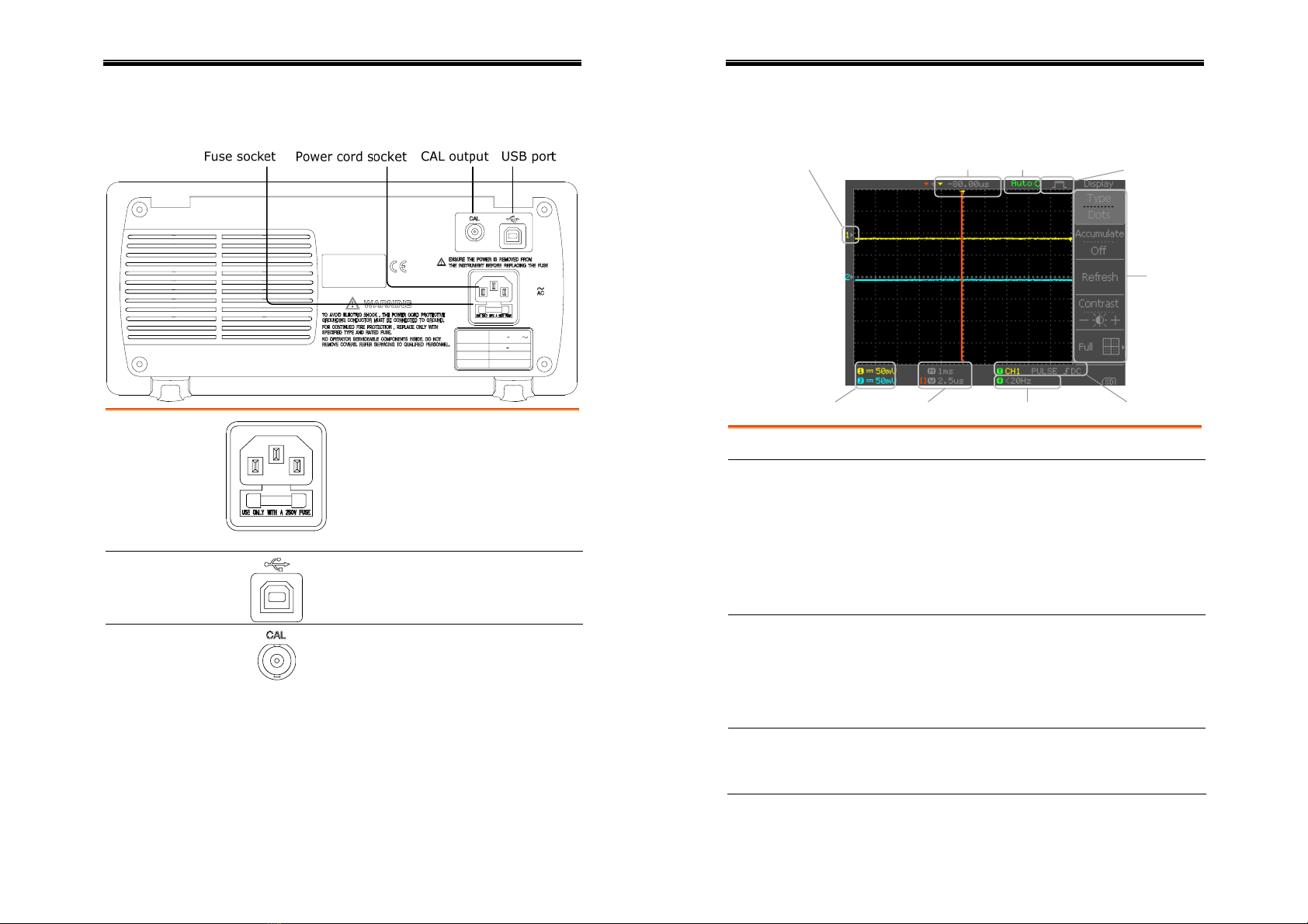
Panel Overview
Front Panel
LCD display TFT color, 320 x 234 resolution, wide angle view
LCD display.
Function keys:
F1 (top) to
F5 (bottom) Activates the functions which
appear in the left side of the LCD
display.
Variable knob
VARIABL
E
Increases or decreases value and
moves to the next or previous
parameter.
Acquire key
Acquire
Configures the acquisition mode
(page52).
Display key
Display
Configures the display settings
(page55).
Cursor key
Cursor
Runs cursor measurements
(page46).
(Continued on next page)

User Manual – SEFRAM 53X2DC
13
Utility key
Utility
Configures the Hardcopy function
(page80), shows the system status
(page72), selects the menu
language (page74), runs the self
calibration (page94), and
configures the probe
compensation signal(page95).
Help key
Help
Shows the Help contents on the
display (page35).
Autoset key
Autoset
Automatically configures the
horizontal, vertical, and trigger
settings according to the input
signal (page37).
Measure key
Measure
Configures and runs automatic
measurements (page43).
Save/Recall key
Save/Recal
l
Saves and recalls image,
waveform, or panel settings
(page75).
Hardcopy key
Hardcop
y
Copies image, waveform, or panel
settings to an SD card (page80).
Run/Stop key
Run/Stop
Runs or stops triggering (page38).
Trigger level
knob
LEVE L
TRIGGE
R
Sets the trigger level (page65).
Trigger menu
key
MENU
Configures the trigger settings
(page65).
Single trigger
key
SINGLE
Selects the single trigger mode
(page72).
Trigger force
key
FORC
E
Acquires the input signal once
regardless of the trigger condition
at the time (page72).
Horizontal menu
key
MENU
Configures the horizontal view
(page57).
User Manual – SEFRAM 53X2DC
14
Horizontal
position knob Moves the waveform horizontally
(page57).
TIME/DIV knob
TIME/DIV
Selects the horizontal scale
(page57).
Vertical position
knob Moves the waveform vertically
(page62).
CH1/CH2 key
CH 1
Configures the vertical scale and
coupling mode for each channel
(page62).
VOLTS/DIV knob
V
O
LTS/DI V
Selects the vertical scale (page62).
Input terminal
CH1
Accepts input signals: 1MΩ±2%
input impedance, BNC terminal.
Ground terminal
Accepts the DUT ground lead to
achieve a common ground.
MATH key
M
AT
H
Performs math operations
(page48).
SD card
connector
Facilitates transferring waveform
data, display image, and panel
settings (page75).
Probe
compensation
output
Outputs a 2Vp-p, square signal for
compensating the probe (page95)
or demonstration.
External trigger
input
EXT TRI
G
Accepts an external trigger signal
(page65).
Power switch
Powers the oscilloscope on or off.
User Manual – SEFRAM 53X2DC
15
Rear Panel
Power cord
socket
Fuse socket
Power cord socket accepts the AC
mains, 100 ~ 240V, 50/60Hz.
Fuse socket holds the AC main
fuse, T1A/250V.
For fuse replacement procedure,
see page99.
USB slave port
Accepts a type B (slave) male USB
connector for remote controlling
the oscilloscope (page73).
Calibration
output
Outputs the calibration signal used
in vertical scale accuracy calibration
(page94).
User Manual – SEFRAM 53X2DC
16
Display
Waveform marker
Vertical status Horizontal status Frequency Trigger condition
Waveform position Trigger status Acquisition
Menu
Waveforms Channel 1: Yellow Channel 2: Blue
Trigger status Trig’d A signal is being triggered
Trig?
Waiting for a trigger condition
Auto
Updating the input signal
regardless of trigger conditions
STOP
Triggering is stopped
For trigger setting details, see page65.
Updates the input signal frequency (the trigger
source signal) in real-time.
Input signal
frequency
“< 20Hz” Indicates that the signal frequency is less
than the lower frequency limit (20Hz) and thus not
accurate.
Trigger
configuration Shows the trigger source, type, and slope. In case
of the Video trigger, shows the trigger source and
polarity.
User Manual – SEFRAM 53X2DC
17
Horizontal
status
Vertical status
Shows the channel configurations: coupling mode,
vertical scale, and horizontal scale.
User Manual – SEFRAM 53X2DC
18
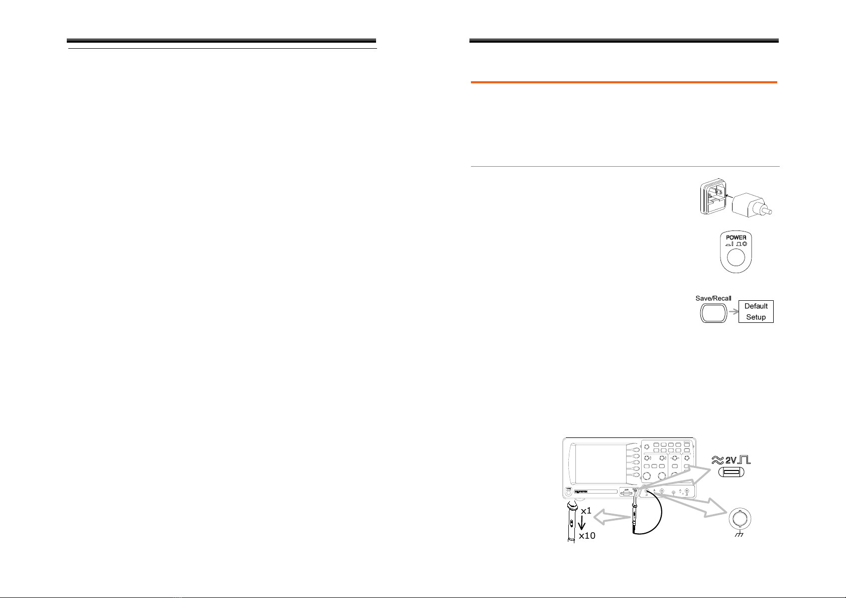
Setting up the Oscilloscope
Background This section describes how to set up the
oscilloscope properly including connecting a
signal, adjusting the scale, and compensating the
probe. Before operating the oscilloscope in a new
environment, run these steps to make sure the
oscilloscope is functionally stable.
Procedure 1. Connect the power cord.
2. Press the power switch. The
display will become active
in approximately 10
seconds.
3. Reset the system by recalling
the factory settings. Press
the Save/Recall key, then
Default Setup. For details of
factory settings, see page34.
4. Connect the probe between the Channel1 input
terminal and probe compensation signal output
(2Vp-p, 1kHz square wave).
5. Set the probe attenuation to x10.
VOLTS/DIV VOLTS/DIV TIME/ DIV
CH 1 MATH CH 2 MENU MENU
Acquir e Display Utility Help
Run/Stop
VARIABLE
FORCE
Autoset
Cursor
SINGLE
HardcopyMeasure Save/Recall
LEVE L
VERTICAL HORI ZONTAL TR I G G E R
Digital Storage Oscilloscope
GDS-1042
40MHz 250MSa/s
CH1
CAT300V
MW 22pF
MAX.300Vpk
1
CH2 EXT TRIG
CAT300V
MW 22pF
MAX.300Vpk
1
XY
User Manual – SEFRAM 53X2DC
19
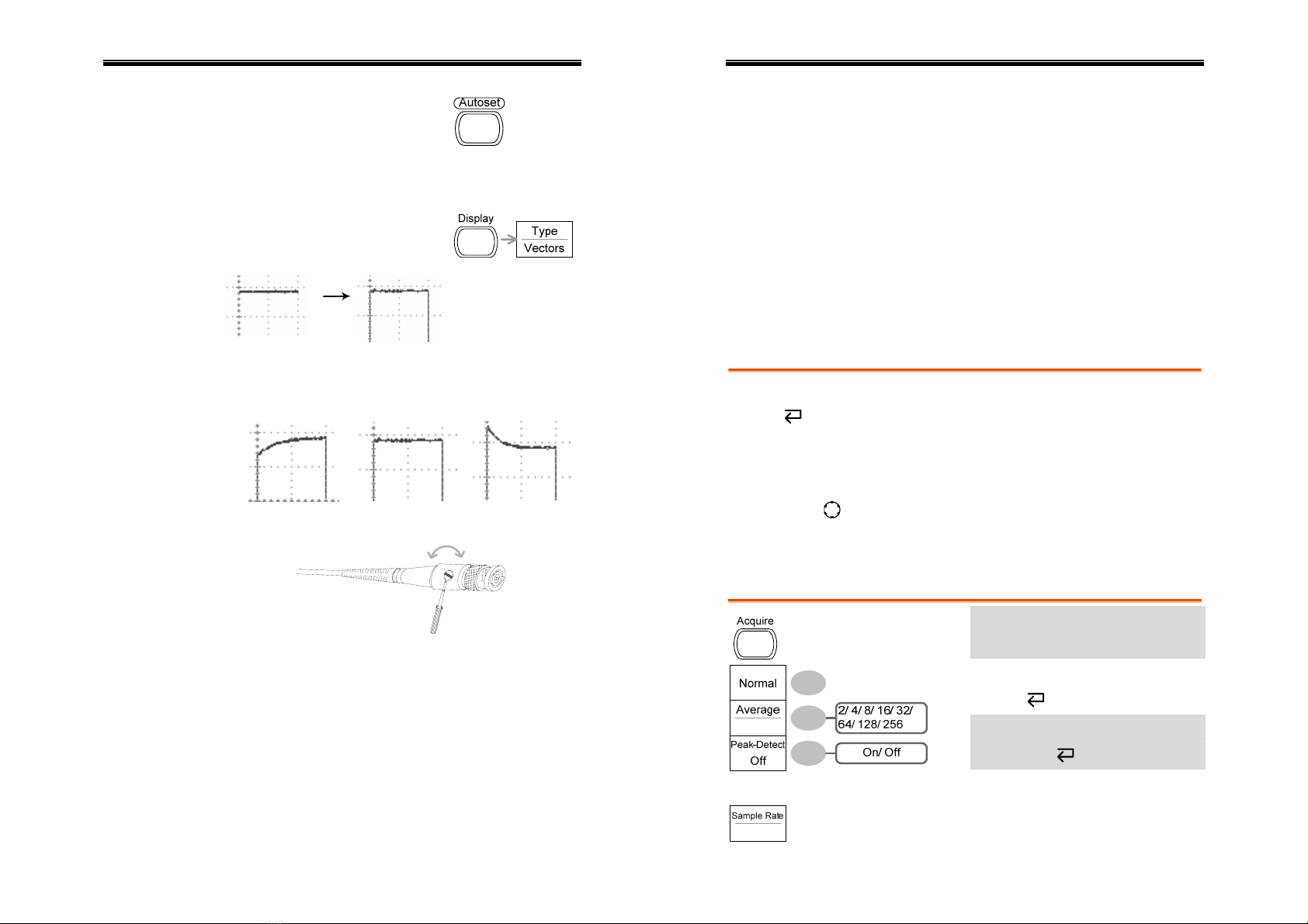
6. Press the Autoset key. A
square waveform will
appear in the center of the
display. For details of the
Autoset, see page37.
7. Press the Display key, then
Type and select the vector
waveform.
8. Turn the adjustment point on the probe to
flatten the square waveform edge.
Over
Compensation Normal Under
Compensation
9. Setting up the oscilloscope is completed. You
may continue with the other operations.
Measurements: page36
Configurations: page52
User Manual – SEFRAM 53X2DC
20
QUICK REFERENCE
This chapter lists the oscilloscope menu tree,
operation shortcuts, built-in help coverage, and
default factory settings. Use this chapter as a
handy reference to access the oscilloscope
functionalities.
Menu Tree and Shortcuts
Normal = Press the functional key for “Normal”
Average = Repeatedly press the functional key for
“Average”
Normal ~
Average = Select a menu from “Normal” to “Average” and
press its functionality key
Normal→VAR = Press the functionality key for “Normal”, and
then use the Variable knob
Acquire key
Select acquisition mode
Normal ~ Peak-Detect
Select average number
Average
Turn peak detect on/off
Peak-Detect
User Manual – SEFRAM 53X2DC
21
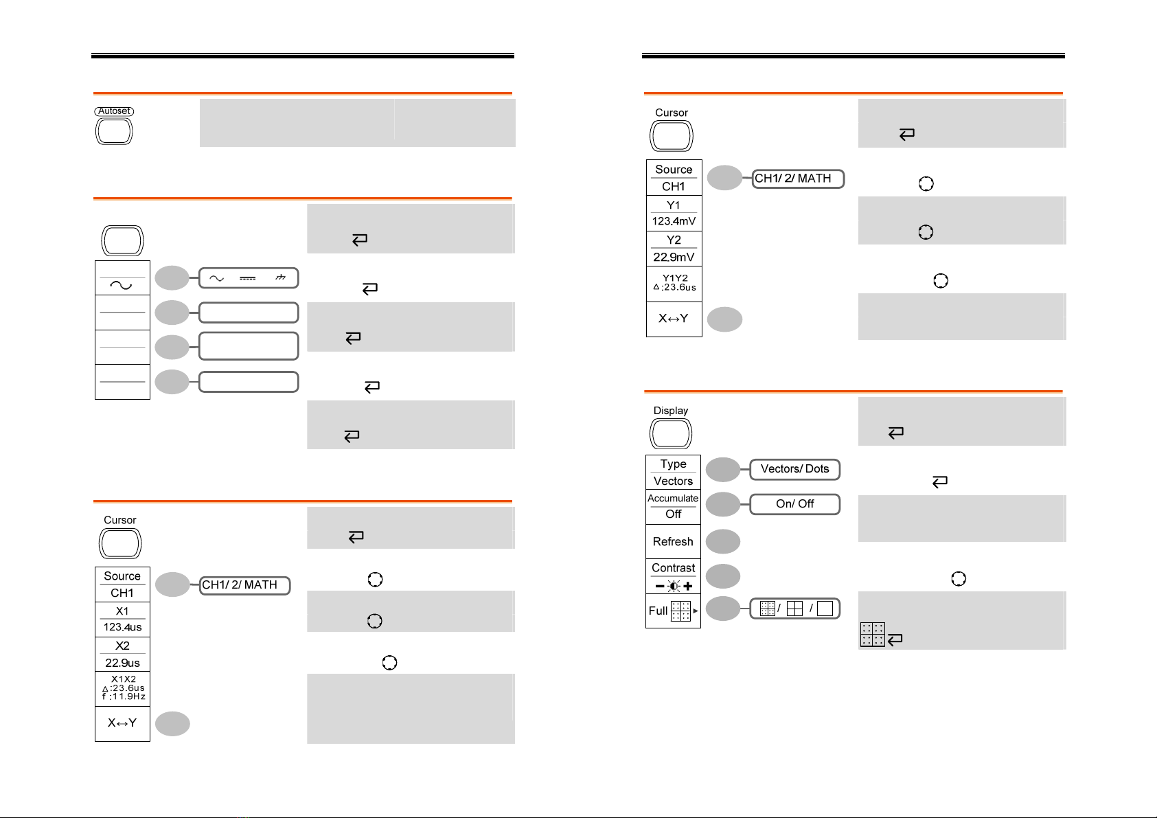
Autoset key
Automatically find signal
and set scale
Autoset
CH1/2 key
Turn channel on/off
CH 1/2
Select coupling mode
Coupling
Invert waveform
Invert
Turn bandwidth limit on/off
BW Limit
Select probe attenuation factor
On/ Off
/ /
On/ Off
(GDS-1102/1062)
x1/ x10/ x100
Coupling
Invert
Off
BW Limit
Off
Probe
x1
CH 1
Probe
Cursor key 1/2
Turn cursor on/off
Cursor
Move X1 cursor
X1→VAR
Move X2 cursor
X2→VAR
Move both X1 and X2 cursor
X1X2→VAR
Switch to Y cursor
X↔Y
User Manual – SEFRAM 53X2DC
22
Cursor key 2/2
Turn cursor on/off
Cursor
Move Y1 cursor
Y1→VAR
Move Y2 cursor
Y2→VAR
Move both Y1 and Y2 cursor
Y1Y2→VAR
Switch to X cursor
X↔Y
Display key
Select waveform type
Type
Waveform accumulate On/Off
Accumulate
Refresh accumulation
Refresh
Set display contrast
Contrast→VAR
Select display grid
User Manual – SEFRAM 53X2DC
23
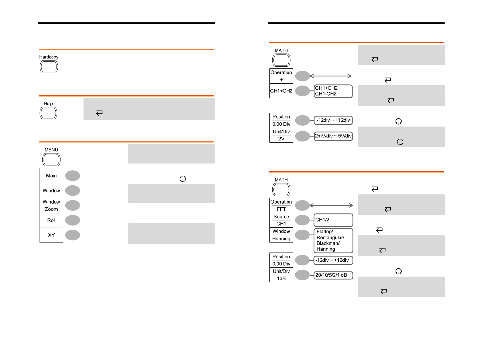
Hardcopy key
→See Utility key (page32)
Help key
Turn help mode on/off
Help
Horizontal menu key
Select main (default) display
Main
Select window mode
Window→TIME/DIV
Zoom in window mode
Window Zoom
Select window roll mode
Roll
Select XY mode
XY
User Manual – SEFRAM 53X2DC
24
Math key 1/2
Math on/off
Math
Select math operation type (+/–)
Operation
Select addition/subtraction
CH1+/-CH2
Set result position
Position→VAR
Math result Volt/Div
Unit/Div→VAR
Math key 2/2
Math on/off
Math
Select math operation type (FFT)
Operation
Select FFT source channel
Source
Select FFT window
Window
Select FFT result position
Position→VAR
Select vertical scale
Unit/Div
User Manual – SEFRAM 53X2DC
25
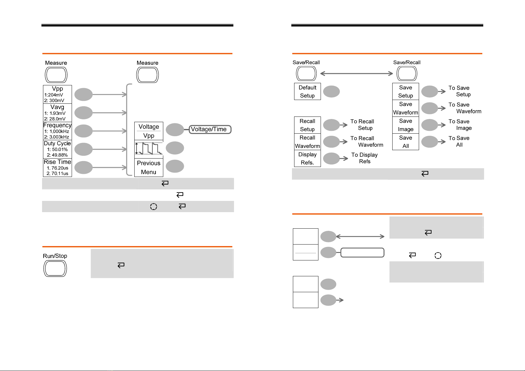
Measure key
Turn on/off measurement Measure
Select measurement type Voltage/Time
Select measurement item VAR or Icon
Go back to previous menu Previous Menu
Run/Stop key
Freeze/unfreeze waveform or trigger
Run/Stop
User Manual – SEFRAM 53X2DC
26
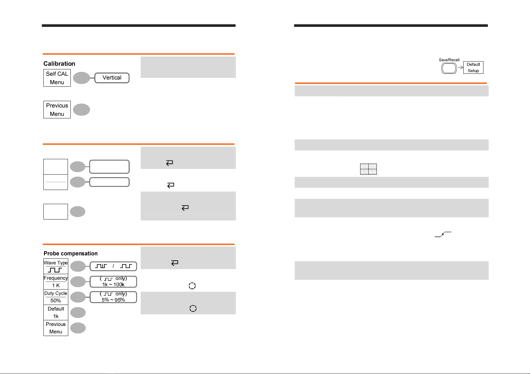
Save/Recall key 1/9
Switch to Save or Recall menu Save/Recall
Recall default setup Default Setup
Save/Recall key 2/9
Select other menu
Recall Setup
Select setup source
Source →VAR
Recall setup
Recall
Go to SD card file utilities
Recall
Setup
Recall
File
Utilities
(SD Card only)
To File Utilities
Recall Setup
Source
Memory Memory/SD Card
File Utilities
User Manual – SEFRAM 53X2DC
27
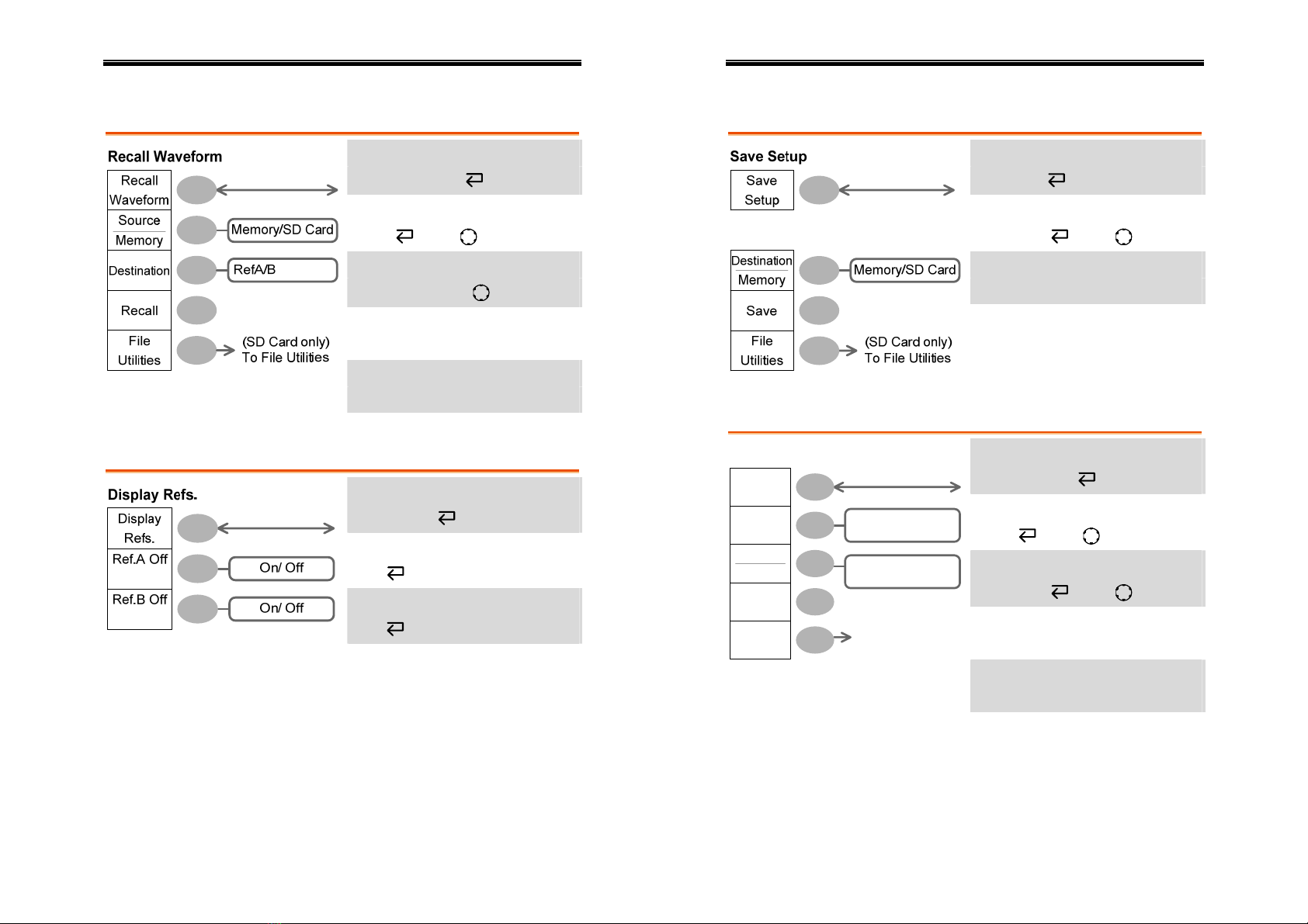
Save/Recall key 3/9
Select other menu
Recall Waveform
Select waveform source
Source →VAR
Select waveform destination
Destination→VAR
Recall waveform
Recall
Go to SD card file utilities
File Utilities
Save/Recall key 4/9
Select other menu
Display Refs.
Turn ref. waveform A on/off
Ref.A
Turn ref. waveform B on/off
Ref.B
User Manual – SEFRAM 53X2DC
28
Save/Recall key 5/9
Select other menu
Save Setup
Select destination
Destination →VAR
Save setup
Save
Go to SD card file utilities
File Utilities
Save/Recall key 6/9
Select other menu
Save Waveform
Select source
Source →VAR
Select destination
Destination →VAR
Save waveform
Save
Go to SD card file utilities
Save
Waveform
Source
Save
File
Utilities
Save Waveform
Destination
Memory Memory/SD Card/
Refs.
(SD Card only)
To File Utilities
CH1/2/Math
Ref A/B
File Utilities
User Manual – SEFRAM 53X2DC
29
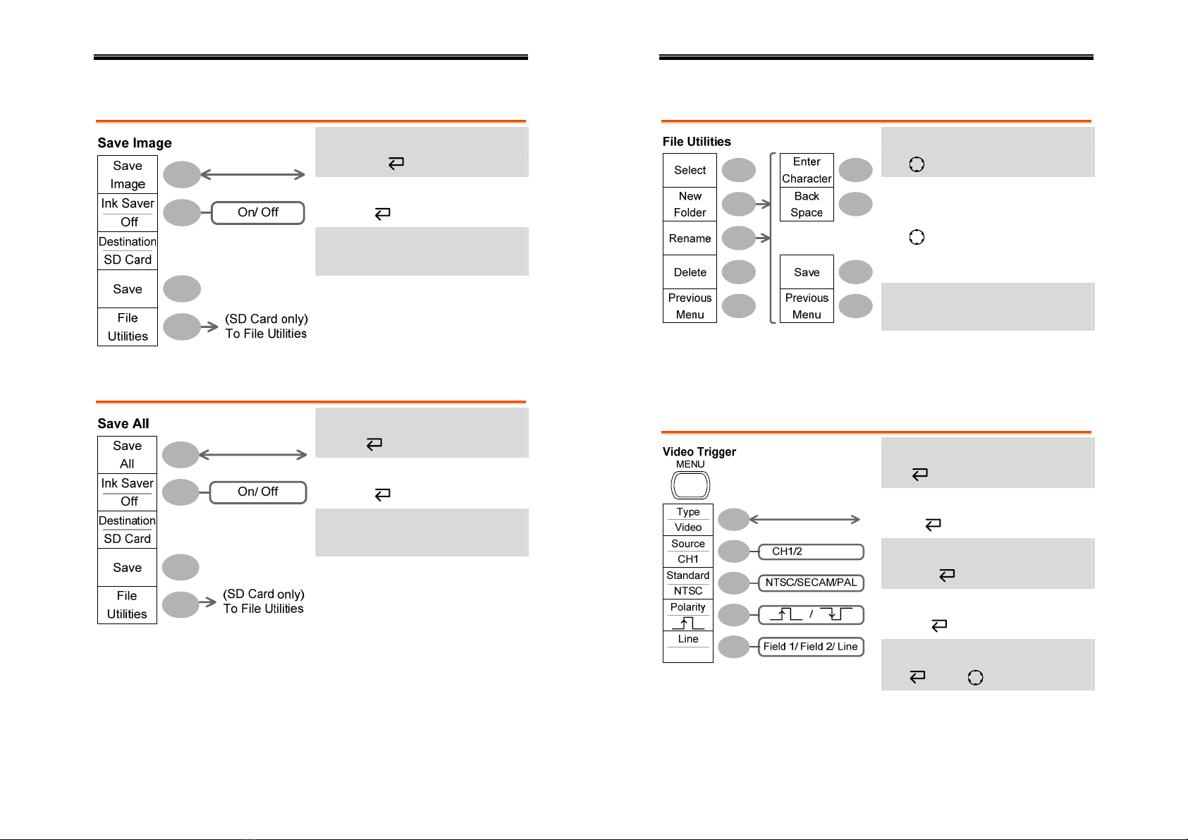
Save/Recall key 7/9
Select other menu
Save Image
Turn on/off ink saver
Ink Saver
Save image
Save
Go to SD card file utilities
File Utilities
Save/Recall key 8/9
Select other menu
Save All
Turn on/off ink saver
Ink Saver
Save all
Save
Go to SD card file utilities
File Utilities
User Manual – SEFRAM 53X2DC
30
Save/Recall key 9/9
Select file/folder
VAR →Select
Create or rename folder/file
New Folder/Rename
VAR →Enter character /
Backspace / Save / Previous
menu
Delete folder/file
Delete
Go to previous menu
Previous menu
Trigger key 1/4
Select video trigger type
Type
Select trigger source
Source
Select video standard
Standard
Select video polarity
Polarity
Select video field/line
Line →VAR
User Manual – SEFRAM 53X2DC
31
Trigger key 2/4
Select edge trigger type
Edge
Select trigger source
Source
Go to slope/coupling menu
(page32)
Slope/Coupling
Select trigger mode
Type
Edge
Source
CH1
Mode
Auto
Slope /
Coupling
CH1/2/Ext/Line
Auto/ Normal
To Slope/Coupling
MENU
Edge Trigger
Mode
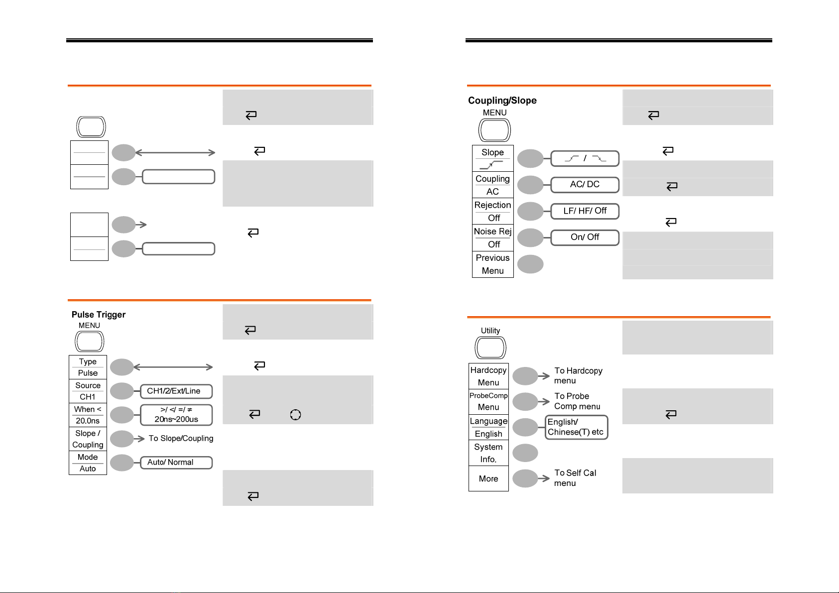
Trigger key 3/4
Select pulse trigger type
Type
Select trigger source
Source
Select pulse tri
gg
er condition and
pulse width
When →VAR
Go to slope/coupling menu
(page32)
Slope/Coupling
Select trigger mode
Mode
User Manual – SEFRAM 53X2DC
32
Trigger key 4/4
Select trigger slope type
Slope
Select trigger coupling mode
Coupling
Select frequency rejection
Rejection
Turn noise rejection on/off
Noise Rej
Go back to previous menu
Previous Menu
Utility key 1/4
Go to hardcopy menu
Hardcopy
Go to probe compensation menu
ProbeComp
Select language
Language
Show system information
System Info.
Go to self calibration menu
More
User Manual – SEFRAM 53X2DC
33
Utility key 2/4
Enter self calibration
Self CAL
Go to previous menu
Previous Menu
Utility key 3/4
Select Hardcopy function
Function
Turn on/off inksaver
Ink Saver
Go to previous menu
Function
Save All
SaveImage/
SaveAll
Previous
Menu
On/ Off
Ink Saver
Off
Hardcopy
Previous Menu
Utility key 4/4
Select probe compensation signal
Wave Type
Set frequency for square wave
Frequency→VAR
Set duty cycle for square wave
Duty Cycle→VAR
Go to previous menu
Previous Menu
User Manual – SEFRAM 53X2DC
34
Default Settings
Here are the factory installed panel settings which
appear when pressing the Save/Recall key→
Default Setup.
Acquisition Mode: Normal
Channel Scale: 2V/Div Invert: Off
Coupling: DC Probe attenuation: x1
BW limit: Off
(GDS-1102, GDS-1062)
Channel 1 & 2: On
Cursor Source: CH1 Cursor: Off
Display Type: Vectors Accumulate: Off
Grid:
Horizontal Scale: 2.5us/Div Mode: Main Timebase
Math Type: + (Add) Position: 0.00 Div
Measure Item: Vpp, Vavg, Frequency, Duty Cycle, Rise
Time
Trigger Type: Edge Source: Channel1
Mode: Auto Slope:
Coupling: DC Rejection: Off
Noise Rejection: Off
Utility Hardcopy: SaveImage,
InkSaver Off
ProbeComp: Square
wave, 1k, 50% duty cycle

User Manual – SEFRAM 53X2DC
35
Built-in Help
The Help key shows the contents of the built-in
help support. When you press a function key, its
descriptions appear in the display.
Help
Applicable keys
Acquire Display Utility Help
Run/Stop
Autoset
Cursor HardcopyMeasure Save/Recall
(Vertical)
CH 1
M
AT
H
CH 2
(Horizontal)
MENU
(Trigger)
MENU
FORCE
SINGLE
Procedure 1. Press the Help key. The
display changes to the Help
mode.
Help
2. Press a functional key to
access its help contents.
(example: Acquire key)
Acquire
3. Use the Variable knob to
scroll the Help contents up
and down.
VARIABL
E
4. Press the Help key again to
exit the Help mode.
Help
User Manual – SEFRAM 53X2DC
36
MEASUREMENT
The Measurement chapter describes how to
properly observe a signal using the oscilloscope’s
basic functionalities, and how to observed a signal
in detailed manners using one of the advanced
functionalities: automatic measurements, cursor
measurements, and math opetaions.
Basic Measurements
This section describes the basic operations required in capturing and
viewing an input signal. For more detailed operations, see the
following chapters.
•Measurements →from page36
•Configurations →from page52
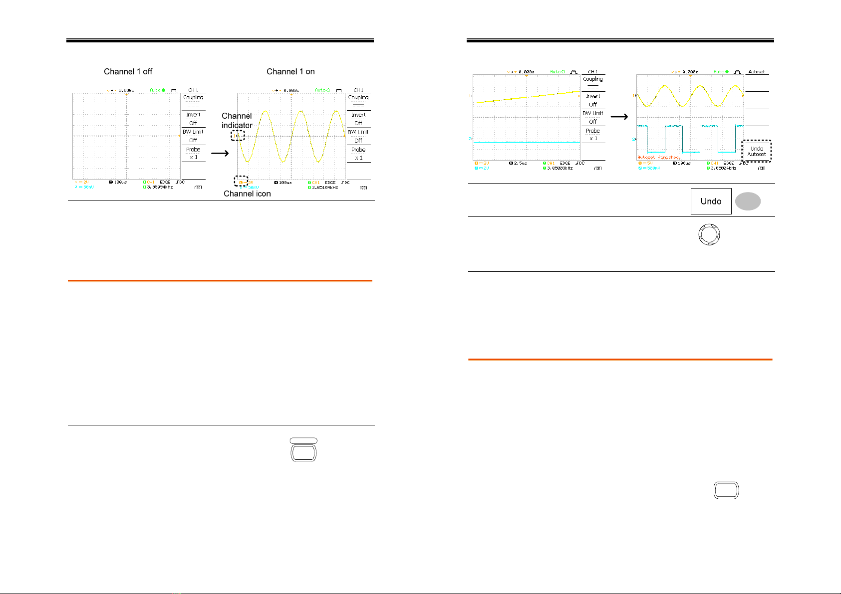
Activating a channel
Activating a
channel To activate an input channel,
press the Channel key, CH1 or
CH2. The channel indicator
appears at the left side of the
display and the channel icon
changes accordingly.
CH 1
or
CH 2
(Continued on next page)
User Manual – SEFRAM 53X2DC
37
De-activating a
channel To de-activate the channel, press the Channel key
twice (once if the channel menu is already
selected).
Using the Autoset
Background Autoset function automatically configures the
panel settings to the best viewing conditions, in the
following way.
•Selecting the horizontal scale
•Positioning the waveform horizontally
•Selecting the vertical scale
•Positioning the waveform vertically
•Selecting the trigger source channel
•Activating the channels
Procedure 1. Connect the input signal to
the oscilloscope and press
the Autoset key.
Autoset
2. The waveform appears in the center of the
display.
User Manual – SEFRAM 53X2DC
38
Undo option
Before Autoset After Autoset
Undoing the
Autoset To undo the Autoset, press
Undo (available for 5 seconds).
Adjusting the
trigger level If the waveform is still
unstable, try adjusting the
trigger level up or down by
using the Trigger Level knob.
L
EVE L
Limitation Autoset does not work in the following situation.
•Input signal frequency less than 20Hz
•Input signal amplitude less than 30mV
Running and stopping the trigger
Background In the trigger Run mode, the oscilloscope
constantly searches for a trigger condition and
updates the signal into the display when the
condition is met.
In the trigger Stop mode, the oscilloscope stops
triggering and thus the last acquired waveforms
stay in the display. The trigger icon at the top of
the display changes into Stop mode.
Pressing the Trigger Run/Stop key
switches between the Run and Stop
mode.
Run/Stop
(Continued on next page)

User Manual – SEFRAM 53X2DC
39
Waveform
operation Waveforms can be moved or scaled in both the
Run and Stop mode. For details, see page57
(Horizontal position/scale) and page62 (Vertical
position/scale).
Changing the horizontal position and scale
For more detailed configurations, see page57.
The horizontal position knob
moves the waveform left or right.
Setting the
horizontal
position The position indicator moves along with the
waveform and the distance from the center point is
displayed as the offset in the upper side of the
display.
User Manual – SEFRAM 53X2DC
40
To select the timebase (scale), turn
the TIME/DIV knob; left (slow) or
right (fast).
TIME/DIV
Selecting the
horizontal scale
Range 1ns/Div ~ 10s/Div, 1-2-5 increment
Changing the vertical position and scale
For more detailed configuration, see page62.
To move the waveform up or
down, turn the vertical position
knob for each channel.
Set vertical
position
As the waveform moves, the vertical position of
the cursor appears at the bottom left corner of the
display.
Run/Stop mode
The waveform can be moved
vertically in both Run and Stop
mode.
To change the vertical scale,
turn the VOLTS/DIV knob; left
(down) or right (up).
V
O
LTS/DI V
Range 2mV/Div ~ 5V/Div, 1-2-5 increments
Select vertical
scale
The vertical scale indicator for each channel on the
bottom left of the display changes accordingly.
This manual suits for next models
3
Table of contents
Other SEFRAM Test Equipment manuals


Popular Test Equipment manuals by other brands


Metrix
Metrix HX0074 user manual

Kyoritsu Electrical Instruments Works, Ltd.
Kyoritsu Electrical Instruments Works, Ltd. 4200 instruction manual

Shineway Tech
Shineway Tech GET-100 user manual

Tektronix
Tektronix 200 Series instruction manual

Dräger
Dräger Alcotest 3000 Instructions for use

AutoWatch
AutoWatch 720 TAB Operator instructions


