Lavo Solutions LavoDose Series User manual
Rev A 07132018 Page | 1
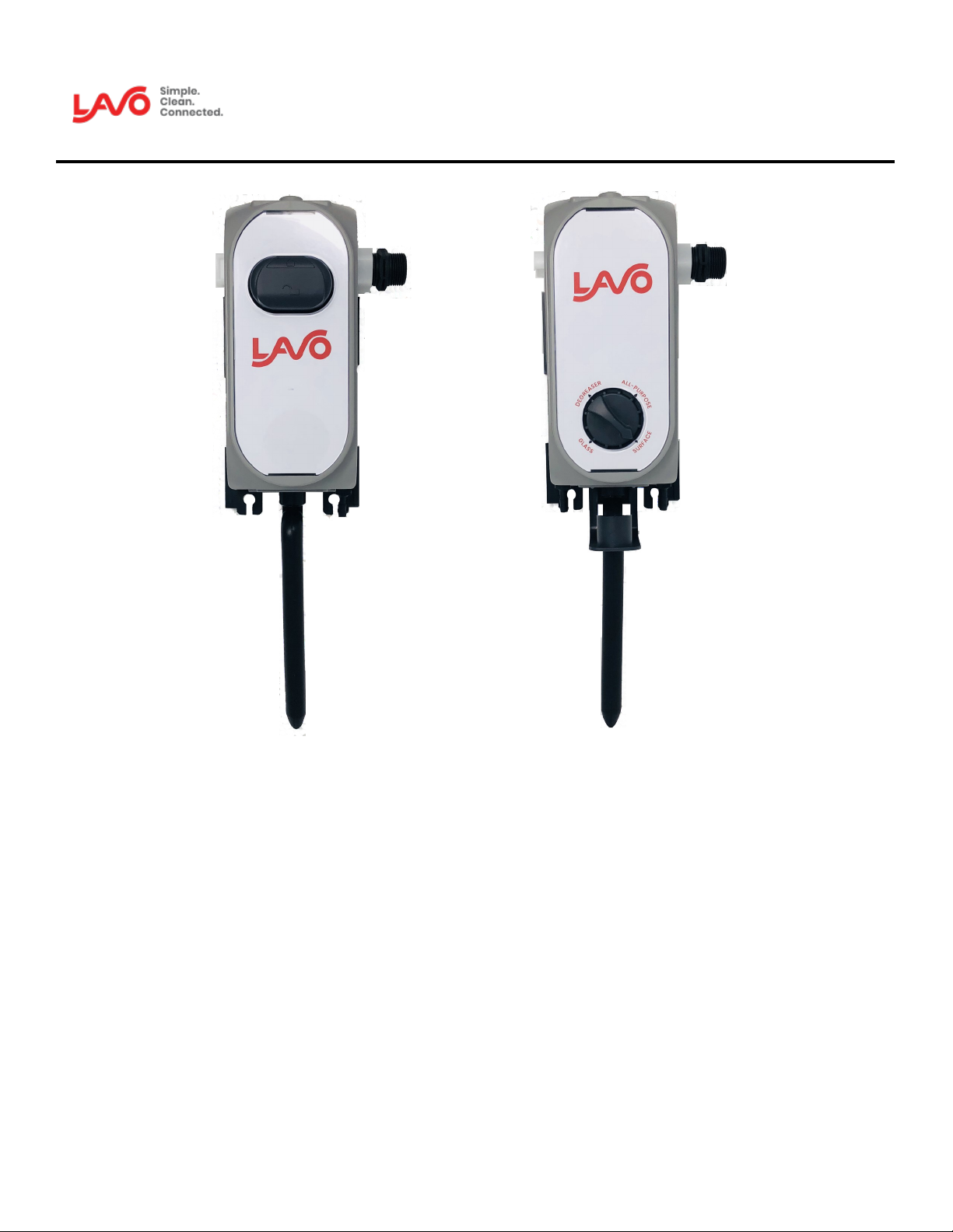
LavoDose Series
INSTRUCTION MANUAL
TABLE OF CONTENTS:
Safety / Tech Specs / Metering Tip Chart 2
Mounng the units 3
Troubleshoong 4
Terms & Condions 5

Rev A 07132018 Page | 2
Safety
READ CAREFULLY BEFORE INSTALLING:
Read this manual carefully for installation instructions.
DO NOT INSTALL the dispenser where it is directly exposed to vapors, chemical fumes, or next to heat
sources.
PROTECT YOURSELF - Always wear personal protective equipment. Use gloves, eye ware, and appropriate
attire when working with chemicals.
FOLLOW THE SAFETY AND HANDLING INSTRUCTION of the chemical manufacturer.
NEVER point the discharge hose at yourself.
Always check local plumbing codes to ensure compliance.
THE DISPENSER SHOULD BE INSTALLED approximately 5’ above the chemical container.
Technical Specifications
Water Inlet Left or Right
Type of Connection ¾” Female GHT
Actuators Button, Dial, Slide
Product Dimensions 9" H x 4" W x 5" D
Operating Pressure 20PSI to 100PSI
Temperature Max 160 degrees F
Tips tested at 40PSI with
water products
Flex Gap Tips tested at 40PSI
with water products
Air Gap
1 GPM 3.5 GPM 1 GPM 4 GPM
Standard
Metering
Tip
Tip Color Oz/Gal Ratio Oz/Gal Ratio
Standard
Metering
Tip
Tip Color Oz/Gal Ratio Oz/Gal Ratio
No Tip 50 2:1 22 6:1 No Tip 38 3:1 16 8:1
Grey 49 3:1 21 6:1 Grey 39 3:1 16 8:1
Black 44 3:1 20 6:1 Black 38 3:1 13 10:1
Beige 32 4:1 14 9:1 Beige 31 4:1 12 10:1
Red 20 6:1 913:1 Red 22 6:1 913:1
White 13 9:1 620:1 White 15 8:1 620:1
Blue 12 11:1 523:1 Blue 13 10:1 622:1
Tan 914:1 432:1 Tan 914:1 527:1
Green 620:1 253:1 Green 718:1 339:1
Orange 524:1 1.8 69:1 Orange 524:1 253:1
Brown 3.4 36:1 1.5 80:1 Brown 428:1 255:1
Yellow 3.3 37:1 1.3 96:1 Yellow 432:1 1.8 68:1
Aqua 2.6 46:1 1121:1 Aqua 344:1 1.5 83:1
Purple 1.3 91:1 0.6 217:1 Purple 277:1 1.1 115:1
Pink 0.7 182:1 0.3 400:1 Pink 1154:1 0.7 182:1
Clear No hole Clear No hole
Ultralean
Tip
Lime 0.5 233:1 0.3 476:1
Ultralean
Tip
Lime 0.5 238:1 0.2 588:1
Burgundy 0.4 333:1 0.2 625:1 Burgundy 0.4 303:1 0.2 769:1
Pumpkin 0.3 435:1 0.15 833:1 Pumpkin 0.3 357:1 0.1 1000:1
Copper 0.2 625:1 0.1 1250:1 Copper 0.29 417:1 0.09 1429:1
Dilution Chart Note: Dilutions will vary. Tested with water.

Rev A 07132018 Page | 3
Mounting the units
STEP 1: Use the backplate as a template to mark the mounting
hole pattern. Drill a hole for the supplied ¼” anchors and mount the
bracket with the screws provided in the accessory kit.
STEP 2: Attach the system to the backplate and slide it down. The
tab will make a clicking noise when the dispenser secured.
STEP 3: Slide in the discharge hose (6.5ft or “S” tube) over the
barbed fitting and make sure it is secured.
STEP 4: Connect the water inlet supply.
STEP 5: Select the metering tip for your desired dilution and
connect the supply tubing.
STEP 6: Connect the ceramic weight on the opposite end of the
tube with the foot valve.
123
5
6
After mounting the backplate, follow these instructions:
STEP 1: Slide the second bracket into the slot from top to bottom on the left side of bracket 1 until they
are properly aligned and secure.
STEP 2: Unlock the left side of the first system by pulling the rear clip to its outward most position as
shown and remove the end cap.
STEP 3: Unlock the right side of the second system by pulling the clip to its outward most position and
remove the water connection.
STEP 4: Insert the coupling nipple into the first unit as illustrated
STEP 5: Connect the second unit to the first
STEP 6: Apply the combined system on to the bracket and complete the installation as per step number
3 above.
Multiple Unit Installation:
4

Rev A 07132018 Page | 4
Troubleshooting
Problem Cause Solution
System does not dispense solution
1. Water inlet strainer is clogged 1. Clean it or replace if necessary
2. Too much water pressure 2. Use a water pressure regulator in case of
more than 100PSI
3. Insufficient water pressure 3. 20PSI is the minimum required pressure.
4. The venturi is clogged
4. Soak venturi in hot water and inspect visually,
gently removing debris. Replace assembly if
needed.
5. Activation valve is clogged by mineral
5. Soak the valve assembly in a solution of hot
water and limescale remover. Replace assemly
if needed.
Water flow won' t stop 1. Activation valve is clogged by minerals or
other water borne debris
1. Soak the valve parts and valve seat in lime-
scale remover to clean. Replace them if neces-
sary
Activation valve is leaking
1. Valve cap not tight enough to seat 1. Firmly hand tighten the valve cap until leak
stops.
2. Not properly positioned 2. Reposition the valve or change it if necessary
Connections and end cap are leaking
1. Missing o-ring in the connection fitting
and / or end cap 1. Apply the o-ring or replace the entire part
2. O-ring in the connections or end cap are
damaged
2. Replace the o-rings or replace the entire end
cap
Flex gap is leaking 1. Flexible membrane is damaged 1. Replace the Flex Gap
A-gap is spraying out and or leaking
1.Limescale film or dirt on the A-gap’s upper
nozzle
1. Soak in hot water and limescale remover to
remove buildup. Replace if necessary
2. Venturi coated with limescale or dirt 2. Soak in hot water and limescale remover to
clean. Replace it if necessary
3. There is a buildup or clog in the discharge
hose 3. Clean the hose to eliminate restriction
4. Discharge hose is above the dispenser 4. Make sure the discharge hose dispenses be-
low the dispenser insuring no back pressure
Improper concentration of chemical or
no suction
1. Insufficient water pressure 1. 14PSI is the minimum working pressure.
2. Metering tip clogged 2. Replace tip
3. Foot valve clogged 3. Soak in hot water, hand clean or change it
4. Venturi clogged 4. Soak in hot water or limescale remover to
clean. Replace it if necessary
5. Air leak in chemical pick up tubing line 5. Check the entire line. Replace the tubing
check the connections and cable tie
6. Product is too thick 6. Change the pick up hose. Switch to a bigger
diameter. (need ¼ x 5/16 coupler)
7. Product container is too far from the sys-
tem
7. The standard installation is positioning the
tank under the system, 5ft max
8. Excess concentration 8. Tip is not the correct one or not inserted fully.
System continues to draw chemical
after the valve is closed
1. Chemical tank is positioned higher than
the dispenser causing siphoning
1. Move chemical container below the dispenser
discharge point

Rev A 07132018 Page | 5
Terms & ConditionsTerms & Conditions
Company warrants its Goods to be free from material defects in material and workmanship for a period of one year ex-
cept: i. when Goods have been modified following delivery and/or subject to improper handling, storage, installation, op-
eration, or maintenance unless those modifications have been authorized in writing by Seller. ii. when an item is pur-
chased by Company as a component part of the Goods, except to the extent to which such item or items are covered by
the warranty, if any, of the original manufacturer. iii. when an item which is a component part of the product has been
furnished by Buyer. iv. no warranty of a component part shall extend beyond the warranty period of the device in which
such component part is incorporated. b. There is no implied warranty of merchantability or of fitness for particular pur-
pose and there are no warranties of any nature except as set forth in paragraph 3 herein. Any claim by Buyer made pur-
suant to Company’s warranty must be made in writing. Company shall have the right to inspect the Goods claimed to be
defective and shall have the right to determine the cause of such alleged defect. All Goods replaced or repaired by Com-
pany under its warranty shall be replaced or repaired F.O.B. Company’s facility. Buyer must notify Company, in writing,
within fifteen (15) days from receipt of Goods of any obvious defect in the product, or shortages, or Company shall have
no obligation to correct such defect. Company shall have the option of re-inspection at Buyer’s plant or its own before
allowing or disallowing Buyer’s claim. Defects that do not impair service shall not be a cause for rejection or recovery
under any warranty. Buyer assumes full responsibility for the use and application of the product. Buyer accepts Compa-
ny’s design and material selection and specifications in placing this order unless other specifications are agreed to in
writing by both parties prior to the manufacture of Goods by Company. Statements and data relating to Products on
Seller’s literature and website are not intended to define the performance of the product in actual usage or in com-
bination with other equipment or processes. These statements should not be used by Customer solely as an indication
of performance or suitability for specific applications or uses.
THE ABOVE WARRANTIES ARE THE SOLE AND EXCLUSIVE WARRANTIES MADE BY SELLER WITH RESPECT
TO ALL PRODUCTS AND SERVICES.
Components and spare parts such as O-rings, squeeze tubes, roller blocks and other plastic components are consid-
ered to be wear parts and are not warranted. Seller shall have no warranty or liability for product that was damaged dur-
ing shipment, product that is not being used in its recommended use, product that is not operated in accordance with the
operating manual and procedures, product that was not properly installed, product used in a manner that is inconsistent
with its designed purpose, product that is subject to a power surge or similar event, products that fail due to usage of a
non Lavo Solutions replacement or spare part or product that was not maintained in accordance with recommended
maintenance programs.
For full terms and conditions, visit:
http://lavosolutions.com/LAVO-T&C-02-2018.pdf
Lavo Solutions, LLC
Worldwide Headquarters
23192 Verdugo, Suite #D
Laguna Hills, CA 92653
O: 949-377-1250
W: www.lavosolutions.com


