Lawler AVAS Instruction Manual

Installation &
Maintenance Manual
M AVAS A
(1)
AVAS
Audio/Visual Alarm System
5330 East 25th Street
Indianapolis, Indiana 46218
Phone (317) 261-1212
Fax (317) 261-1208
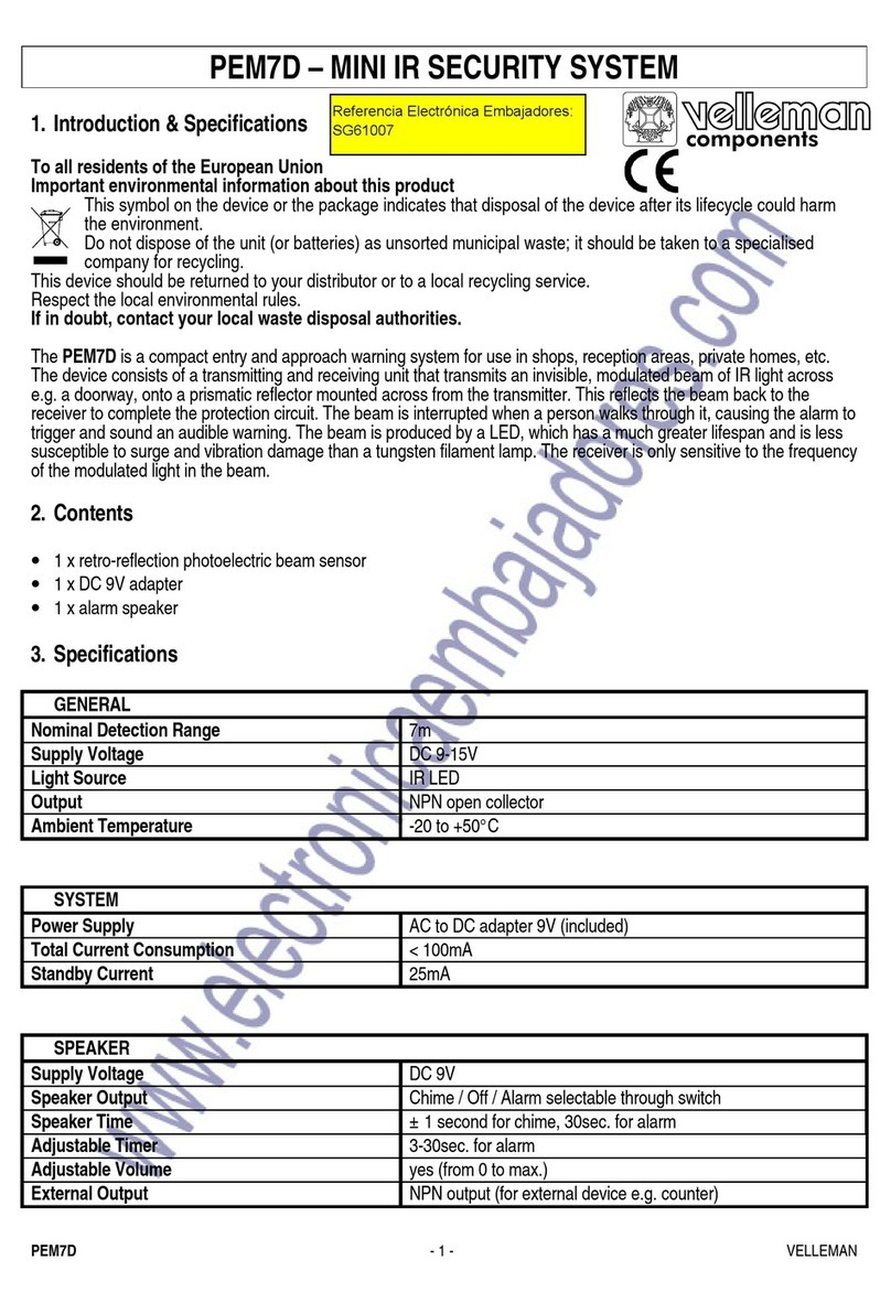
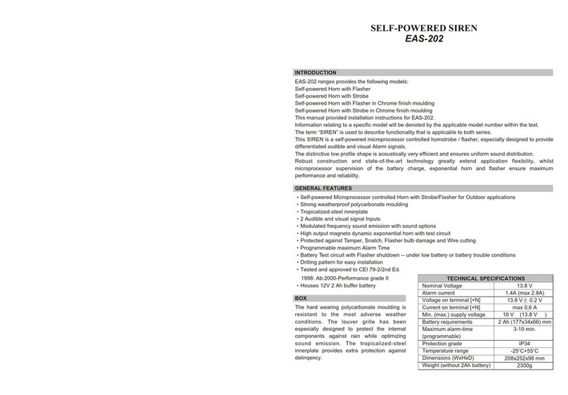
Description
The Audio/Visual Alarm System is designed to give
a visual and audible warning in cases where water
temperature exceeds a pre-programmed setpoint. In
addition, the alarm system can control an optional
solenoid valve, shutting down the ow of water if
necessary. The probe temperature is displayed on
a bright 3-digit LED display, and access to the unit
programming is done thru the password protected
keypad on the front face. A keylock switch is pro-
vided to override the audible alarm.
Specifications
Probe Range: -58 to +302°F
Input: Thermistor (1000Ω @ 25°C)
Accuracy: ±1°
Resolution: ±1 Digit
Supply Voltage: 120 VAC
Ambient Temperature: 32 to +131°F
Storage Temperature: -4 to + 176°F
Display: 3-digit, Red, ½″High
Installation
The Alarm System comes with a standard 120 VAC
pigtail. The controller uses a SPDT relay powering the
horn, and light, as well as an optional normally closed
solenoid valve. Please see Lawler Manufacturing,
Inc. about approved solenoid valves to use with the
alarm system so as not to overload the controller.
Observe proper polarity when connecting to the ter-
minal block on the back panel of the enclosure. The
wiring diagram can be found on page 3.
Upon powering the unit up the solenoid valve will
open allowing the ow of water. If the set point is
exceeded, the valve will close, and the audible and
visual alarms will come on. The audible alarm can
be bypassed with the keylock switch. The unit will
return to normal when the temperature goes below
the sum of the set point and the high alarm minus the
hysteresis.
Parameters
Code Description Range Default
SP Set Point r1 to r2 120°F
r0 Hysteresis 1 to 20 2°F
r1 Lower Value Set Point -50 to +150°F -50°
r2 Upper Value Set Point -50 to +302°F 200°F
d0 Heating or Cooling Ht/Co Co
d2 Time for Defrosting 0 to 59 Min 0 Min
d8 Interval between Defrost 1 to 24 Hrs 1 Hr
c0 Min. Stop Time 0 to 59 Min Load 0 Min
c1 Continuous Cycle Time 0 to 24 Hrs 0 Hrs
c2 On Time of Fault Cycle 0 to 999 Min 0 Min
c3 Off Time of Fault Cycle 0 to 999 Min 0 Min
A0 Alarm differential/hysteresis 1° to 20° 5° F
A1 Max alarm temp 1° to 20° 10° F
A2 Min alarm temp 1° to 20° 90° F
A7 Alarm time valaidation 0 to 99 Min 0 Min
P0 Temperature Scale Option 0/F°
P1 Ambient Probe Adj. -10 to +10°F 0°F
P4 Decimal Point Option No
H0 Factory Settings Option 0
H4 Address 0 to 999 0
H5 Parameter Access Code 00 to 99 00
H6 Ambient Probe Type Option PTC
t0 Max Temp on Display -50 to +302°F 200°F

(2)
The actual point of alarm is the sum of the set
point and the "high alarm". The system will re-
turn to normal when the temperature reaches the
sum of the set point and the "high alarm" minus
the hysteresis.
Parameter Programming
Set Point (SP) is the only parameter the user
can access without code protection
• Press SET. SP Text will appear on the display
• Press SET again. The real value is shown on the
display.
• The value can be modied with the UP and DOWN
arrows.
• Press SET to enter any new values.
• Press SET and DOWN at the same time to quit
programming or wait one minute and the display
will automatically exit programming mode.
The keyboard code can be reset to ZERO by
turning off the controller and turning it on again
while keeping the SET key depressed.
Access to all code protected parameters.
• Press SET for 8 seconds. The access code value
00 is shown on the display. (Unit comes with code
set at 00 from factory).
• With the UP and DOWN arrows, code can be set
to user needs.
• Press SET to enter the code. If code is correct, the
rst parameter label is shown on the display (SP).
• Move to the desired parameter with the UP and
DOWN arrows.
• Press SET to view the value on the display.
• The value can be modied with the UP and DOWN
arrows.
• Press SET to enter the value and exit to text pa-
rameter.
• Repeat until all necessary parameters are modied.
• Press SET and DOWN at the same time to quit
programming or wait one minute and the display
will automatically exit programming mode.
Display Messages
In normal operation, the probe temperature will be
shown on the display. In case of alarm or error, the
following messages will be shown: The alarm LED
indicates and active alarm, it will ash if an alarm is
cleared but alarm condition still exists.
• ALH = High Temp Alarm
• ALL = Low Temp Alarm
• Er = Memory Error
• -- = Short-Circuit Probe Error
• oo = Open Probe Error
Alarm can be cleared by pressing the DOWN button.
The alarm LED will ash while alarm condition per-
sists but the alarm message will not be shown.
Warning: This product contains chemicals known to the
State of California to cause cancer and birth defects or
other reproductive harm.
(Installer: California law requires that this warning be
given to the consumer.)
For more information: www.oehha.org/prop65
GUARANTEE
We guarantee the Lawler Mixing Valve to be free from
def ects in workmanship and material, and for a pe-
riod of one year from date of purchase, will replace
any parts found by us to be defective. We will not be
held responsible, however, for any labor incidental
to, or for any damages caused by defective mate-
rial. Each mixing valve is thoroughly inspected and
tested under actual conditions at our factory.

(3)
AVAS Wiring Diagram
