New Cosmos Electric NV-100D User manual

1 Point type Toxic Gas Detection /
Alarm System
Model NV-100D
Instruction Manual
●
Keep this instruction manual where it is readily accessible.
●
Thoroughly read this instruction manual before using the equipment so it can be used safely and correctly.
New-Cosmos Electric Co., Ltd.
Instruction manual No.
GAE-008-01
December 2004

Table of Contents
1. Introduction.............................................................................................................................................................1
2. Safe Operation........................................................................................................................................................1
3. Unpacking...............................................................................................................................................................2
4. System Structure ....................................................................................................................................................3
5. Dimensions and Part Names..................................................................................................................................4
5-1 Indicator and Alarm Unit.................................................................................................................................4
5-2 Gas Detector ..................................................................................................................................................5
6. Installation and Wiring ............................................................................................................................................6
6-1 How to Install the Indicator and Alarm Unit ....................................................................................................6
6-2 How to Install the Gas Detector......................................................................................................................7
6-3 Wiring Method ................................................................................................................................................8
7. Operating Instructions...........................................................................................................................................11
7-1 Notes to Users..............................................................................................................................................11
7-2 Procedures...................................................................................................................................................11
7-3 Operation of the equipment..........................................................................................................................13
7-4 When an Alarm Occurs ................................................................................................................................14
7-5 How to replace Batteries (when the equipment has a backup power source).............................................14
7-6 Maintenance Function..................................................................................................................................15
8. Maintenance and Inspections...............................................................................................................................22
8-1 Regular Inspections (Inspections that you are responsible for)...................................................................22
8-2 Periodic Inspections .....................................................................................................................................23
9. Troubleshooting....................................................................................................................................................24
10. Specifications........................................................................................................................................................25
10-1 Indicator and Alarm Unit...............................................................................................................................25
10-2 Gas Detector ................................................................................................................................................25
11. Consumable Parts and Spare Parts.....................................................................................................................26
12. Warranty ...............................................................................................................................................................26
13. Service Life...........................................................................................................................................................26
14. Glossary................................................................................................................................................................27

1
1. Introduction
Thank you for purchasing a NV-100D single-point toxic gas detection /alarm system.
This system is used to prevent leakage of toxic gas. This equipment continuously monitors for leakage of
toxic gas, and indicates when a preset level has been exceeded by a lamp and sound.
Thoroughly read this instruction manual before using the equipment so it can be used correctly. Read the
instruction manual of the gas detector as well.
Symbols
The following symbols are used for safety purposes:
DANGER
:Indicates an imminently hazardous situation which, if not avoided, will result in death or
serious injury
WARNING
:Indicates a potentially hazardous situation which, if not avoided, will result in death or serious
injury
CAUTION
:Indicates a potentially hazardous situation which, if not avoided, may result in minor injury or
moderate injury. It may also be used to alert against unsafe practices.
MEMO
:Operational advice and or instruction.
2. Safe Operation
Carefully read the following so you can use the equipment correctly.
Read and understand all applicable laws and regulations and ensure that you are complete compliance with
the said laws and regulation before installing or operating the equipment.
Installing, wiring, and other works concerning the equipment should be carried out by qualified persons,
following all applicable federal, state, and local health and safety laws and regulations including OSHA.
Operation checks using actual gas are very dangerous because combustible gas may explode and toxic
gas is harmful. An inspection must be carried out beforehand by persons with sufficient expertise or our
service staff.
DANGER
Ground the equipment in order to prevent electric shocks.
In case of an alarm, carry out your predetermined measures for gas leakage.
This equipment is not explosion-proof. Install it in a non-hazardous location.
WARNING
Do not dissemble, alter the equipment, or change its structure and electric circuit. It may affect the
performance of the equipment.
If you control the interlock of external equipment etc. with equipment’s output signal, we are not
responsible for any injuries or damages caused by it.
The equipment is not waterproof. Install it in a place where it will not get wet.
Follow all related laws and regulations when using the equipment.
Do not use any equipment that generates electrical noises such as cellular phones or radio-
communications within 30 cm of the alarm panel.
CAUTION

2
3. Unpacking
The following standard components are packed together with the Gas Detector/alarm. Carefully check the
contents against the list when unpacking. If any components are missing or damaged, contact our dealer /
agency.
NV-100D main body 1
Gas detector head 1
Without a backup power source 1 piece
Fuse 1A With a backup power source 2 pieces
Part to embed the panel (embedded panel only) 1 set
NV-100D instruction manual (this book) 1
Test results of the equipment 1
Options (separately sold)
Rainproof cover KW-31 for a detector head KS-2D 1
3
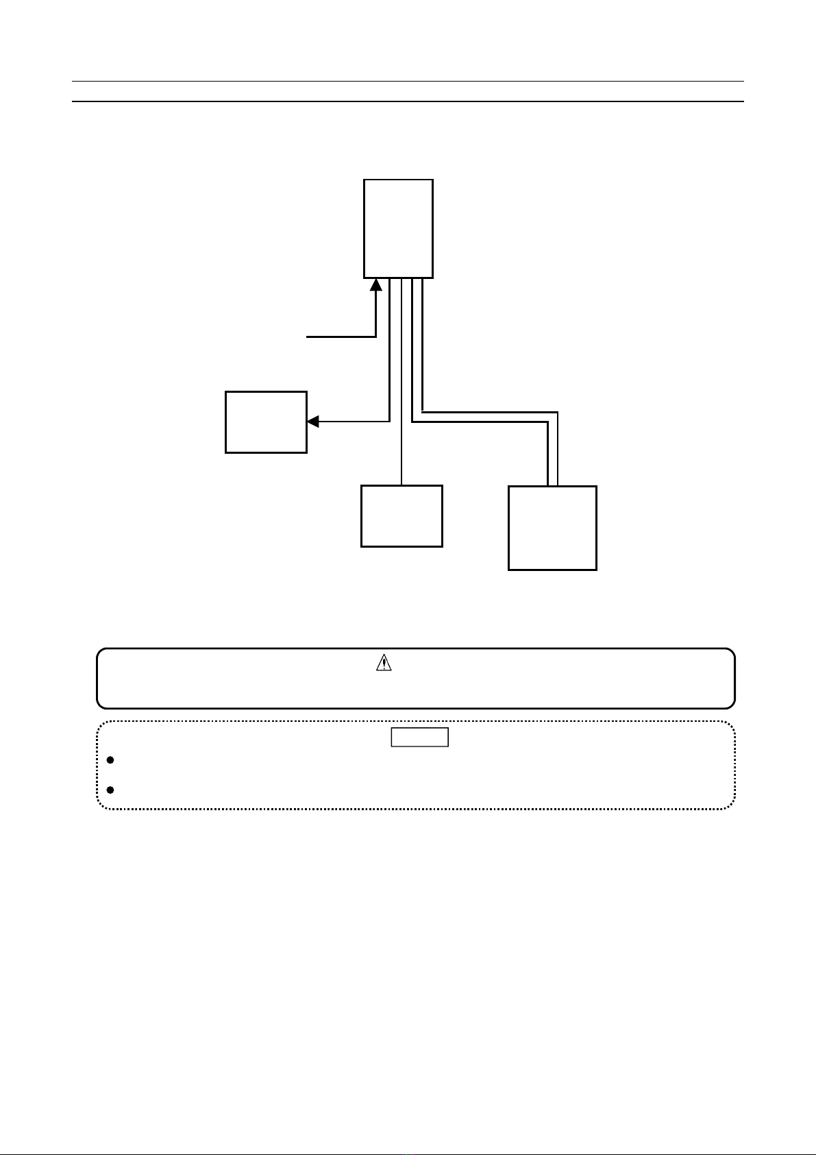
4. System Structure
This equipment consists of a part that detects gas (gas detector head) and a part that indicates gas
concentration and sets off an alarm (indicator and alarm unit). The parts are connected by cables.
Indicator
and alarm
unit
NV-100D
Suction type
gas detector
PS-2DP
Diffusion type
gas detector
KS-2D
Control
device
Power source
AC100/240V
(DC24V)
Alarm
contact
2C shielded cable
2C shielded cable
2C cable
Fig. 1 System Structure
The indicator and alarm unit is not an explosion-proof construction. Install it in a non-hazardous area.
CAUTION
One gas detector (either diffusion or suction type gas detector) can be connected. Use a rainproof
cover (option) if you install the equipment outdoor.
The number of cores of cables differs according to the gas detector connected.
MEMO

4
5. Dimensions and Part Names
5-1 Indicator and Alarm Unit
1
2
RESET
BZSTOP
POWER
ALARM BACKUP
HGFESRPAPB
5
0
TAZB2ZA2ZB1ZA1COMNARAS TB BZ
15
2
9
10
3
11
5
4
26
27
12
6
8
28
1
14
13
7
29
18 19 20 21 23 22
2‑φ6
24 25
113 71.5
17
16
CD
A.SET
0
6
4
2
10
8
Fig. 2. Dimensions of the Indicator and Alarm Unit (without a backup power source)
1
2
RESET
BZSTOP
POWER
ALARM BACKUP
HGFESRPAPB
5
0
TAZB2ZA2ZB1ZA1COMN
AR
AS TB BZ
FUSE
30
31
32
3‑φ6
70
110
CD
A.SET
0
6
4
2
10
8
Fig. 3. Dimensions of the Indicator and Alarm Unit (with a backup power source)

5
No. Name Function
1Gas concentration
indicator
This LCD bar graph meter with backlight indicates gas concentration and the
preset alarm value. The peak value continues to blink even after the reading
value goes down after an alarm.
2 Power lamp (POWER) It is green during normal operation and orange when the sensor failure. It
blinks green when the equipment is turned on and also after a failure has been
taken care of to show that the equipment is warming up.
3 Alarm lamp (ALARM) A red lamp blinks to indicate a gas leakage and lights up when the buzzer stops.
4Buzzer stop key
(BZ STOP) When this key is pressed, the alarm sound stops and the blinking Alarm lamp
lights up.
5 Reset key (RESET) When this key is pressed after the buzzer stops and reading lowers, the Alarm
lamp and peak hold go off. They do not go off when the key is pressed before
the buzzer stops.
6Alarm setting key (
△▽
)Use these keys to change the preset alarm value. Press
△
to increase the
set value and press
▽
to decrease it.
7 Backup lamp (BACKUP) It is off in normal state and it blinks red during a power failure. (Equipment with
an optional backup power source only.)
8 Message window Displays messages during operation of functions.
9 Mode switch Use to set mode such as maintenance mode 1, 2, etc.
10 Function switch Use to set functions.
11 Enter key Use to set functions.
12 SOUND volume control To control alarm buzzer volume. Adjust it when you want to lower the sound.
13 Program connector Use to write in the program. Usually, it is not used.
14 Program switch Use to write in the program. Usually, select the left side.
15 Power switch A switch to open/close the equipment’s power source.
16 AC power source fuse 5.2 I 20L 1Aglass fuse.
17 Jumper pin It is used for various settings. No setting by customer is necessary.
18 Sensor signal check
terminal (SIGNAL) A terminal to check gas sensor signals
19 Sensor current check
terminal (CURR CHECK) Not used.
20 Battery test key
(B. TEST) To test the battery’s life. This key cannot be used if the equipment does not
have a backup power source.
21 Sensor current
adjustment control
(CURR) Not used.
22 Test button (TEST) Use this button for performance tests.
23 Test control (TEST) A control to adjust what the indicator indicates when the Test button is pressed.
It is adjusted so the full scale is indicated.
24 Zero adjustment volume
(ZERO) A control to adjust the gas sensor’s zero point. Adjust this in maintenance
mode 2.
25 Span adjustment volume
(SPAN) A control to calibrate the indicated value of gas concentration. Adjust this in
maintenance mode 2.
26 Analog output adjustment
volume (L) A control to adjust analog output 4 mA (1V)
27 Analog output adjustment
volume (H) A control to adjust analog output 20 mA (5V)
28 Terminal block A terminal block to connect external wirings
29 Speaker To sound an alarm
30 Backup power source
unit Supplies power from built-in battery in the event of a power failure.
31 Battery switch A switch to open/close the battery of the optional backup power source.
32 Battery fuse 5.2 I 20L 1A glass fuse
5-2 Gas Detector
Concerning dimensions of the gas detector, refer to its instruction manual.

6
6. Installation and Wiring
6-1 How to Install the Indicator and Alarm Unit
The equipment can be hang on the wall or embedded.
The indicator and alarm unit is not an explosion-proof construction. Install it in a non-hazardous area.
WARNING
The indicator and alarm unit must be installed in a place where someone is always present and is
easy to read so that taking countermeasures and notifying others in case of an alarm is possible.
Do not place the indicator and alarm unit in a place with vibration, electric noise, or corrosive gas.
Avoid places with a high temperature or humidity as well.
CAUTION
As to the gas detector to be connected, refer to its instruction manual.
MEMO
(1) How to install on the wall
1. Make holes on the wall as shown in Fig. 4.
2. If the equipment has a backup power source, attach two mounting plates on the top and bottom of
the equipment.
3. Align the anchors with the holes then insert a bolt in the upper hole.
4. Insert it in the hole on top of the equipment, insert the other bolt in the bottom hole, then tighten
both bolts.
70
113
3‑φ7
3‑φ7
60
113
2‑φ30
(ケーブル入線口)
2‑φ7
With a backup power sourceWithout a backup power source
(Cable inlet)
Fig. 4 Dimensions for Hanging the Equipment on the Wall
Size of mounting holes is different if the equipment has a backup power source.
If the equipment has no backup power source, a cable can be connected from the back and bottom o
f
the equipment. If the equipment has a backup power source, a cable can be connected only from
the bottom.
Leave a 30 cm space under the equipment’s body for maintenance work. If the equipment has a
backup power source, also leave a 30 cm space on the right side of the equipment for changing
batteries.
MEMO
7
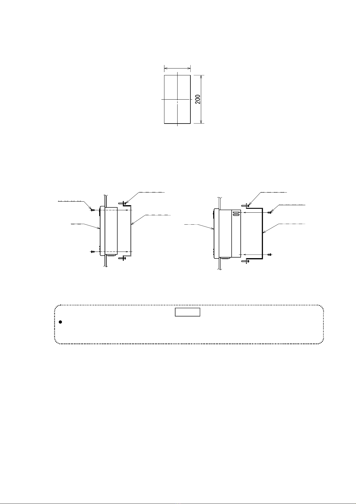
(2) How to embed on a panel
1. Cut out a rectangular opening in the panel as shown in Fig. 5.
110
Fig. 5 Dimensions to Cut a Panel
2. Insert the equipment into the opening from front.
Attach the backplate on back of the equipment using the attaching screws as shown in Fig. 6.
Then, fasten it to the panel with fixing screws. The equipment can be attached to a 1.6 to 6 mm
thick panel.
固定ネジ
取付ネジ
埋込金具
本体
パネル
Attaching screw
Equipmen
t
Panel Fixing screw
Backplate
Without a backup power source
取付ネジ
固定ネジ
埋込金具
本体
パネル
Panel
Equipment
Fixing screw
Attaching screw
Backplate
With a backup power source
Fig. 6 Embedding on a Panel
Leave a 30 cm space under the equipment’s body for maintenance work. If the equipment has a
backup power source, also leave a 30 cm space on the right side of the equipment for changing
batteries.
MEMO
6-2 How to Install the Gas Detector
Refer to the gas detector’s instruction manual.
8
6-3 Wiring Method
Refer the gas detector’s instruction manual as well.
Turn OFF the indicator and alarm unit’s power before opening the cover of the gas detector.
Opening the cover when the power is on may cause a fire.
Ground the equipment’s main body and gas detector.
WARNING
Make sure that terminal codes of the indicator and alarm unit side and gas detector side are correct.
Use shielded cables and wire them separated from the power line as much as possible.
When it is necessary to carry out external wiring work for intrinsically safe explosion proof, connect
Zener barrier (BT-150).
Carry out external wiring work for intrinsically safe explosion proof following “Safety Guidelines for
Plants’ Electric Equipment.”
Use 0.75 mm to 2 mm
2
two-core shielded cables to wire intrinsically safe circuits. Wiring for
intrinsically safe circuits should be less than 500 m.
Carry out good grounding work.
Do not combine intrinsically safe circuits with non-intrinsically safe circuits.
CAUTION
(1) Wiring of power source
Prepare a circuit breaker to connect the power source to the indicator and alarm unit.
(2) Connecting to the gas detector
Make sure that terminal codes on the indicator and alarm unit side and gas detector side are correct.
Use shielded cables and wire them as far away from the power line as possible.
(3) Connecting the external alarm contact
Use the external alarm contact only for external alarm equipment and alarm indicators.
Make sure that load current and voltage do not exceed the contact’s capacity.
If you control interlock, etc. using this equipment’s external alarm contact, we are not responsible for
any injuries or damages caused by it.
CAUTION
First alarm contact 1c dry contact (AC100V 2A load resistance) COM
ZA1
ZB1
Second alarm contact 1c dry contact (AC100V 2A load resistance) COM
ZA2
ZB2
Trouble alarm contact 1c dry contact (AC100V 2A load resistance) COM
TA
TB
Buzzer contact 1a dry contact (AC100V 2A load resistance) COM
BZ
Terminal for external alarm stop (AS) and external reset (AR) AS
AR
N
Alarm can be stopped or reset externally by connecting an external switch.
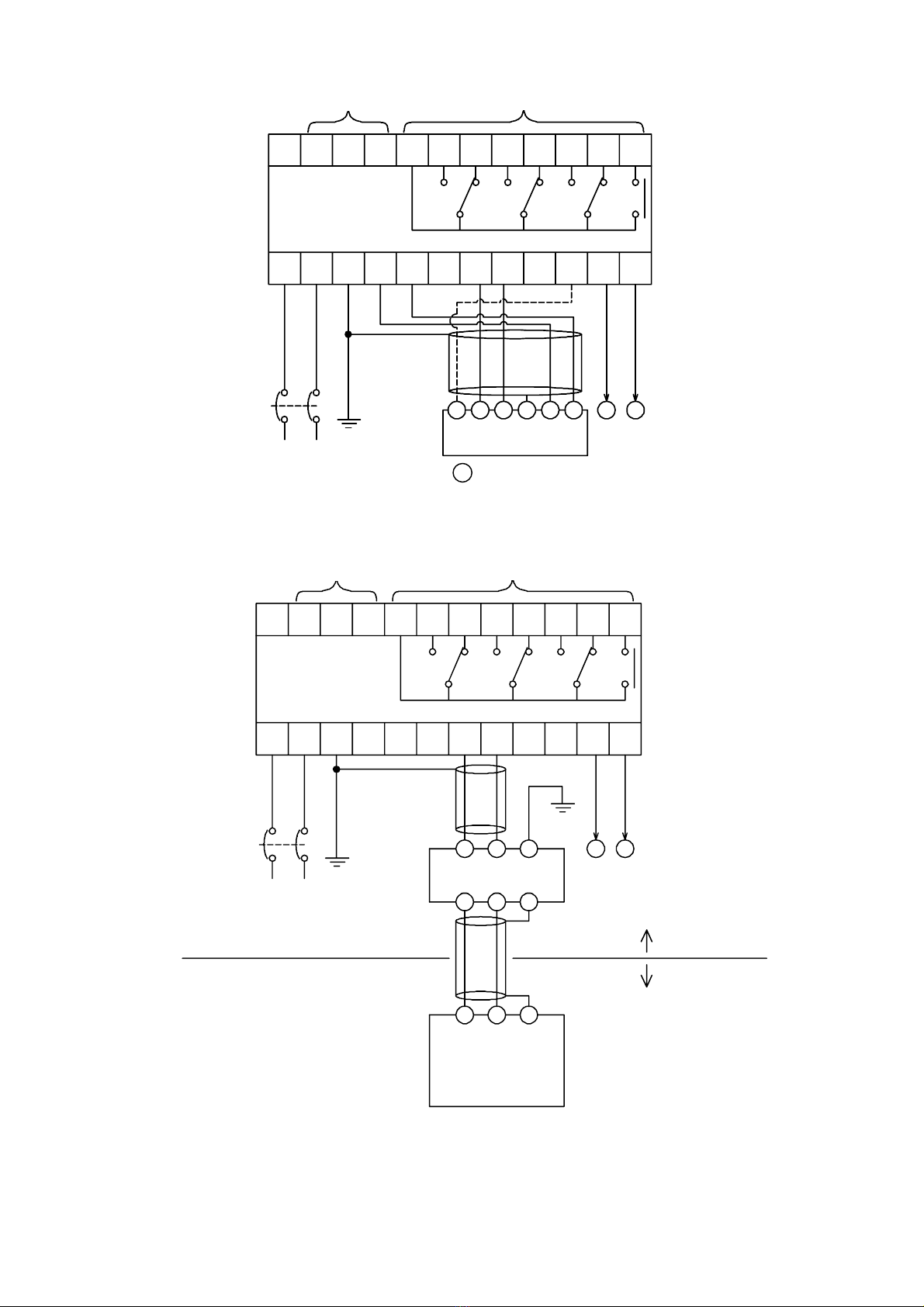
(4) Connecting the analog output terminal
Gas concentration around the gas detector can be continuously monitored and recorded by
connecting a recorder to the analog output terminal. There are G(+) and H(-) terminals on the
terminal block. Standard output is 4-20 mA. Input resistance of the recorder should be 500 or
less.

9
COMN
ARAS ZA1 ZB1 ZA2 ZB2 TA TB BZ
FGHEPAPB
R(P) S(N)
制御機器外部スイッチ
空
上段端子台
下段端子台
+−
4〜20mA
遮断器
(+) (−)
AC100/200V
(DC24V)
接地
(1〜5V)
アナログ出力
CD
拡散式ガス検知部
CDE
KS‑2D
2Cシールド
ケーブル
空空
External switch Control device
Upper
terminal
block
Lower
terminal
block
Idle
Idle Idle
2C
shielded
cable
Breake
r
Grounding Diffusion gas detector
KS-2D Analog output
Fig. 7 Circuit (Diffusion type gas detector)
COM
NARAS ZA1 ZB1 ZA2 ZB2 TA TB BZ
FGHEPAPB
R(P) S(N)
制御機器
外部スイッチ
空
上段端子台
下段端子台
+−
アナログ出力
4〜20mA
遮断器
(+) (−)
AC100/200V
(DC24V)
接地
(1〜5V)
CD空空
吸引式ガス検知部
PB
PA
CDE
PS‑2DP/PS‑2DE
2Cシールド
ケーブル
ケーブル
2C
※ エゼクター吸引式の場合、ポンプ配線は不要です
External switch Control device
Upper
terminal
block
Lower
terminal
block
Idle
Idle Idle
2C
shielded
cable
Breaker
Grounding Suction gas detector
PS-2DP / PS-2DE Analog output
2C
cable
* An eductor suction type gas detector does not
require wiring of a pump.
Fig. 8 Circuit (Suction type gas detector)
10
COMNARAS ZA1 ZB1 ZA2 ZB2 TA TB BZ
FGHEPAPB
R(P) S(N)
制御機器
外部スイッチ
空
上段端子台
下段端子台 CD空空
+−
アナログ出力
4〜20mA
遮断器
(+) (−)
AC100/200V
(DC24V)
接地
(1〜5V)
PB
PA
CDEF
PS‑4DP
吸引式ガス検知部
5Cシールド
又は
4Cシールド
ケーブル
にして使用してください。
※ Fを結線した場合は、流量低下警報機能が利用できますので
指示警報部ファンクションスイッチ8番を有効(OFF側)
External switch Control device
Upper
terminal
block
Lower
terminal
block
Idle
Idle Idle
5C shielded
cable or 4C
shielded
cable
Breake
r
Grounding Suction gas detector
PS-4DP Analog output
* When is connected, a flow decline alarm function can
be used. Use function switch no.8 on the indicator and
alarm unit. (Select “OFF”.)
F
Fig. 9 Circuit (Suction type gas detector PS-4DP)
COMN
ARAS ZA1 ZB1 ZA2 ZB2 TA TB BZ
FGHEPA PB
R(P) S(N)
制御機器
外部スイッチ
空
上段端子台
下段端子台 CD
空空
+−
4〜20mA
遮断器
(+) (−)
AC100/200V
(DC24V)
接地
(1〜5V)
アナログ出力
E
ツェナーバリア
BT‑150
CDE
11 12
A種接地
CDE
2Cシールド
ケーブル
2Cシールド
ケーブル
非危険場所
危険場所
拡散式ガス検知部
KS‑2D
吸引式ガス検知部
KS‑2DE
又は
External switch Control device
Upper
terminal
block
Lower
terminal
block
Idle
Idle Idle
2C shielded
cable
Breake
r
Grounding Zener barrier
BT-150 Analog output
A good
ground
Hazardous
area
Non-hazardo
us area
2C shielded
cable
Diffusion gas detector
KS-2D
or
suction gas detector
PS-2DE
Fig. 10 Circuit (In case of intrinsically safe explosion proof)
11
7. Operating Instructions
7-1 Notes to Users
Make sure that all parts are correctly connected before turning on the power. Check that the
terminals of the gas detector and indicator and alarm unit are correctly connected.
Do not connect a load to the external alarm contact that exceeds the rated capacity.
CAUTION
7-2 Procedures
(1) Turning ON the power
1. Turn ON the Power switch. If the equipment has a backup power source, turn ON the Battery
switch as well.
2. Gas concentration indicator displays gas concentration and first and second preset alarm values.
The Power lamp blinks green to show that the equipment is warming up.
3. The Power lamp stops blinking and lights up green and normal operation starts. Warming up
takes about thirty seconds.
4. Warm up the equipment for about ten minutes until indication becomes stable.
(2) Zero adjustment
Make sure that there is no gas around the gas detector before carrying out zero adjustment. If zero
adjustment is carried out when there is gas around the gas detector, the indicator cannot indicate
correct values.
Carry out analog adjustment for trial run or after replacement of the gas sensor.
CAUTION
1) Correction by the auto zero function
The reading is automatically corrected to zero by pressing a button. Use this adjustment daily for
minor zero point corrections. Refer to 7-6 (1).
2) Analog zero adjustment
Adjust zero by turning the zero adjustment volume. Use this method for most zero adjustments.
Refer to 7-6 (2).
3) Zero suppression mode
The indicator sometimes flickers when indication jumps one dot or so because of a small amount
of gas around the gas detector. In this event, turn ON Function Switch 4 to select zero
suppression mode and eliminate flickering of the indicated value. Refer to 7-3 (6).
12
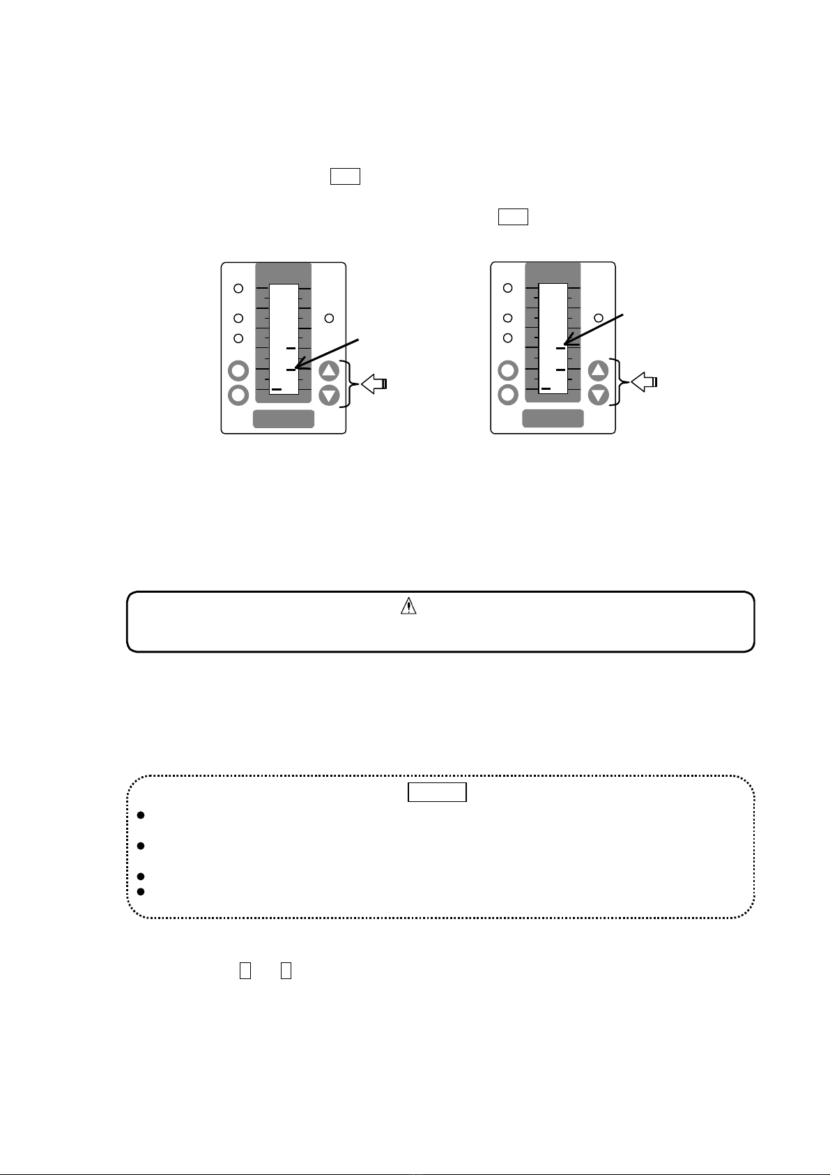
(3) Setting alarms
Alarm value is set as you specified at the time of delivery. If you want to change it, follow the
procedures below.
1. Confirm that it is under the normal mode (Mode Switch 0) then press the Enter key.
2. Message window displays AP 1. Use the Alarm Setting keys (
△▽
) to change the first preset
value.
3. Press the Enter key and the message window displays AP 2. Use the Alarm Setting keys (
△▽
)
to change the second preset value.
POWER
ALARM
2
1
RESET
BZSTOP
BACKUP
A
P 2
Change the
second
preset
alarm value
POWER
ALARM
2
1
RESET
BZSTOP
BACKUP
A
P 1
Change the
first preset
alarm value
4. Press the Enter key again to complete the change of preset alarm value. Message window
disappears and normal operation starts.
(4) Buzzer volume
1) Adjusting the buzzer volume
Turning down the SOUND volume control can lower buzzer volume. The sound is set at max at
the time of delivery.
Keep the sound at max unless there is a particular reason for lowering it
CAUTION
(5) Equipment with a backup power source
The equipment with a backup power source has a function to check the battery’s life. Follow the
procedures below to check the battery’s life.
1. Confirm that normal mode (Mode Switch 0) is selected then hold the Battery Test Switch down for
five seconds. The Backup lamp blinks red and message window indicates the battery voltage.
The equipment has a function to check the battery’s life. Use this function during monthly
inspections, etc.
Battery test is only a simple test. To find out the battery’s actual life, turn OFF the Power switch and
carry out a discharge test.
Replace battery every three years.
The Battery Test key cannot be used in maintenance mode 1 and 2. Use the key in normal mode.
MEMO
(6) Checking analog output
Terminal block G and H can output 4-20 mA (1-5V).
1. Connect a tester to terminal block G and H. Adjust the indicated value at zero using the Test
control while pressing down the Test button. Check output on the tester. You do not need to
adjust if it reads 4 mA (1V). If it is off, adjust by turning Analog Output Adjustment control (L).
2. Adjust the indicated value at full scale using the Test control while pressing down the Test button.
Check output on the tester. You do not need to adjust if it reads 20 mA (5V). If it is off, adjust by
turning Analog Output Adjustment volume (H).

13
3. Repeat procedures 1 and 2 several times until 4-20 mA(1-5V) is read.
7-3 Operation of the equipment
(1) When gas is detected
When gas concentration around the gas detector becomes high and the reading of the gas
concentration indicating bar graph exceeds the first preset alarm value, the first Alarm lamp blinks and
an alarm sound (four short beeps) is heard. When the reading exceeds the second preset alarm
value, the second Alarm lamp blinks. At the same time, the peak hold value blinks on the indicator.
(2) When the Buzzer Stop (BZ STOP) key is pressed
An alarm sound stops and the blinking Alarm lamp on the indicator unit lights up. Peak hold is still
indicated in this state.
When using an external alarm stop terminal, you can stop the buzzer using an external switch.
(3) When the Reset key is pressed
When the Reset key is pressed after the buzzer is stopped and the reading lowers to below the preset
alarm value, the Alarm lamp and peak hold go off.
When using an external reset terminal, you can reset using an external switch.
Reset does not work by pressing the Reset key before operating the BZ STOP key.
MEMO
(4) In case of a failure
1) When the gas detector is out of order
The Power lamp lights up orange, an alarm sound (four short beeps) is heard, and message
window displays the type of the failure.
(Failure E: Disconnected cable, F: Flow decline)
2) When the Buzzer Stop (BZ STOP) key is pressed.
When the BZ STOP key is pressed, the alarm sound stops.
3) After the failure has been fixed
The Power lamp changes from orange to blinking green and the equipment goes into warming up
state. After warming up, it returns to its normal state.
(5) Equipment with a backup power source
1) In case of a power failure
The Backup lamp blinks red and battery starts supplying power to the equipment so that the
equipment can continue monitoring gas leakage.
2) When battery voltage lowers below the final voltage
The battery automatically stops discharging power and the equipment stops entirely.
3) When power is recovered
The Backup lamp goes off and the equipment returns to its normal operation. When power is
recovered after the equipment stops because of over discharge, the equipment starts operating
from warming up state.
(5) Function switches
If you change setting for function switches, the equipment cannot perform as it is supposed to, for
example, alarm does not go off even when there is gas leakage. Do not change setting unless you
completely understand features of Function switches.
CAUTION
The equipment’s Function switches (No. 10 on Fig. Dimensions of the Indicator and Alarm Unit in 5-1)

14
Function switch
no. Function OFF ON
1 Alarm sound N/A Always ON
2 Alarm sound ON/OFF ON OFF
3 Ten second alarm delay ON/OFF OFF ON
4 Zero suppression function ON/OFF OFF ON
5 Self-retention / Auto-restore Self-retention Auto-restore
6Trouble alarm : normally open /
close Normally
open Normally
close
7Heater disconnection alarm ON/OFF
−
Always ON
8 Flow decline alarm ON/OFF ON OFF
7-4 When an Alarm Occurs
WARNING
In case of an alarm, carry out your predetermined measures for gas leakage.
When gas leaks indoors, open windows and doors for better ventilation.
Use our Gas Leak Detector XP-702S / XP-703D to efficiently find where the gas is leaking from.
MEMO
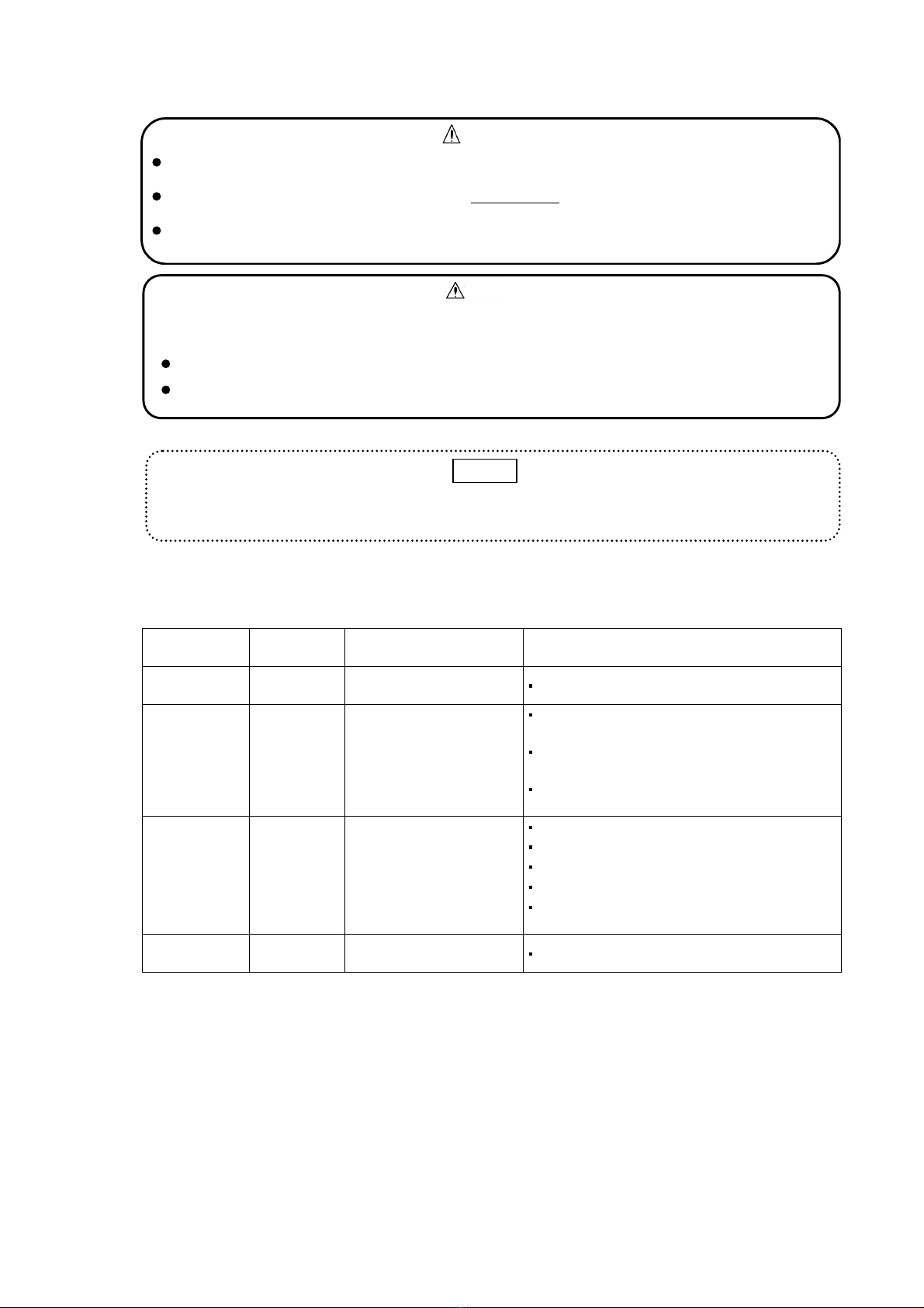
7-5 How to replace Batteries (when the equipment has a backup power source)
Replace two batteries at the same time.
Do not catch the harness when attaching the battery cover.
CAUTION
1. Detach the battery cover on the right side of the backup power source unit.
2. Detach the battery connector and take out the batteries.
3. Insert new batteries and attach the connector.
4. Put the battery cover back.
1
2
RESET
BZSTOP
POWER
ALARM BACK UP
A.SET
0
6
4
2
10
8
1
2
RESET
BZ STOP
POWER
ALARM BACK UP
A.SET
0
6
4
2
10
8
Fig. 11 How to replace the Batteries
15
7-6 Maintenance Function
WARNING
When adjustment in a mode is completed, always set the Mode switch at zero to return to normal
mode. If the switch is left at other mode, the equipment cannot alarm gas leakage correctly.
Message window displays “preset value” and “ ” alternately during maintenance mode to
prevent you from forgetting to return to normal mode after adjustment.
Do not change the setting for modes 3 to 9. If the setting is changed, the equipment cannot properly
alarm you of a gas leakage.
NV-100D has maintenance mode function. Select a mode using the Mode switch to use each function.
Functions of modes are described in the following table.
Mode switch
no. Mode name Function Remarks
0Normal
mode Normal state to monitor
gas leakage Use the equipment in this mode.
1Maintenance
mode 1 Auto zero and span
adjustment
Auto zero and span adjustment can be
carried out by pressing a button.
Use this adjustment for minor zero point and
sensitivity corrections
Alarm contact and buzzer contact do not
operate.
2Maintenance
mode 2 Analog zero and span
adjustment
Adjust zero and span using volumes.
Use this method for most adjustments.
Cancel auto zero and span function.
Cancel zero suppression function.
Alarm contact and buzzer contact do not
operate.
3 9
−
Only used for adjustment
at factory Do not use them.
Re-check the following items in normal mode after zero and span adjustments are performed in
maintenance mode 1 and maintenance mode 2.
The zero point is correctly indicated at zero.
The gas concentration is correctly indicated when calibration gas is applied.
CAUTION
Use auto zero and span adjustment daily for minor zero point and sensitivity corrections, and use
analog zero and span adjustment for normal corrections.
MEMO

16
(1) Maintenance mode 1 Auto zero and span adjustment
1) Auto zero adjustment (Maintenance mode 1)
①
Set the Mode switch at 1 to select
maintenance mode 1.
②
Make sure that there is no gas around the
gas detector then press down the BZ
STOP key until the Power lamp goes off.
③
The Power lamp lights up again and the
indicated value is automatically corrected
to zero.
④
Set the Mode switch at zero to return to
normal mode.
If the indicated value is outside the auto zero adjustment range when the BZ STOP key is pressed,
the message window will display a blinking “Err” indication and auto zero adjustment will be
impossible. If this occurs, carry out analog zero adjustment in maintenance mode 2.
MEMO
POWER
ALARM
2
1
RESET
BZSTOP
BACKUP
40
POWER
ALARM
2
1
RESET
BZSTOP
BACK UP
40
Off
POWER
ALARM
2
1
RESET
BZSTOP
BACKUP
40
On
Corrected
to zero.
POWER
ALARM
2
1
RESET
BZSTOP
BACKUP
Check that the
reading
returns to zero

17
2) Auto span adjustment
①
Set the Mode switch at 1 to select
maintenance mode 1.
②
Set the auto span preset value (any
number between 10 and 100) using the
Alarm Setting keys (
△▽
).
③
Confirm that the zero point is at zero and
apply calibration gas to the gas detector
for a minute.
④
If peak hold value does not match
calibration gas concentration, press down
the Reset key until the Power lamp goes
off.
⑤
The Power lamp lights up again and the
peak hold value is automatically
corrected to the auto span preset value.
⑥
Set the Mode switch at zero to return to
normal mode.
POWER
ALARM
2
1
RESET
BZSTOP
BACKUP
40
POWER
ALARM
2
1
RESET
BZSTOP
BACKUP
40
Auto span
preset
value
POWER
ALARM
2
1
RESET
BZSTOP
BACKUP
40
POWER
ALARM
2
1
RESET
BZSTOP
BACKUP
40
Peak hold
Off
POWER
ALARM
2
1
RESET
BZSTOP
BACKUP
40
On
POWER
ALARM
2
1
RESET
BZSTOP
BACKUP
Make sure there
is no gas around
the gas detector
and check to see
if the indicator
reads 0.

18
⑦
Finally apply the calibration gas and
check to see if the calibration
concentration is indicated correctly
If the indicated value is outside the auto zero adjustment range when the RESET key is pressed,
the message window will display a blinking “Err” indication and auto zero adjustment will be
impossible. If this occurs, carry out analog span adjustment in maintenance mode 2.
MEMO
Note that a gas leak alarm and external output will be generated when calibration gas is applied in
normal mode.
CAUTION
Check the
calibration
concentration.
POWER
ALARM
2
1
RESET
BZSTOP
BACKUP
Table of contents
Other New Cosmos Electric Security System manuals


