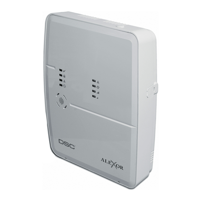
DSC Maxsys PC6010 User guide

System Manual
PC6O1O Software Version 2.1
• W A R N I N G •
This manual contains information on limitations regarding product use and function and information
on the limitations as to liability of the manufacturer. The entire manual should be carefully read.
®

Contents
Section 1: Introduction .................................................. 1
1.1 Introduction to PC6010 ..................................... 1
1.2 Using PC6010 Manuals ...................................... 1
Section 2: System Overview .......................................... 2
2.1 Overview............................................................ 2
2.2 Module Specifications....................................... 3
Section 3: Installation and Wiring ................................ 5
3.1 Planning the System.......................................... 5
3.2 Out of the Box ................................................... 5
3.3 Terminal Descriptions ....................................... 5
3.4 Current Ratings – Alarm Control Panel and
Modules ............................................................. 6
3.5 Ebus Operation and Wiring .............................. 7
3.6 PC6204 Power Supply ....................................... 7
3.7 Backbone Operation and Wiring ...................... 8
3.8 Zone Wiring ....................................................... 8
3.9 Specialized Zone Wiring .................................... 9
3.10 Programmable Output Wiring ......................... 9
3.11 Wiring Powered Devices (AUX, SAUX+) ........ 10
3.12 Telephone Line Wiring .................................... 10
3.13 Bell Output Wiring (BELL+ and BELL-) ............ 10
3.14 Earth Ground Wiring ....................................... 10
3.15 Mounting the Cabinet, Control Panel and
Modules ........................................................... 10
3.16 Applying Power (AC and Battery) .................. 11
3.17 Lithium Batteries ............................................. 11
Section 4: Module Enrollment .................................... 12
4.1 Enrolling Keypads and Modules .................... 12
4.2 Enrolling the First Keypad .............................. 12
4.3 Enrolling All Other Keypads ........................... 12
4.4 Enrolling PC6108A, PC6204, PC6216, PC6400,
and PC6820 Modules ...................................... 12
4.5 Enrolling PC6442 and PC6443 Modules ......... 12
4.6 Deleting Modules ............................................ 13
4.7 Confirming Modules ....................................... 13
Section 5: Programming the PC6010 .......................... 14
5.1 Introduction to Programming ........................ 14
5.2 Programming Using Hotkey Numbers ........... 14
5.3 Programming Decimal Data ........................... 14
5.4 Programming Hexadecimal Data ................... 15
5.5 Programming Toggle Options ........................ 15
Section 6: Keypad Operation and User Types ............ 16
6.1 Introduction..................................................... 16
6.2 User Types ........................................................ 16
6.3 “Warning - Security Reduced” Messages ...... 17
6.4 Time and Date Display .................................... 17
6.5 Keypad Lockout .............................................. 17
6.6 Keypad Tampers .............................................. 17
6.7 Keypad Backlighting ....................................... 17
Section 7: System Operation and Programming....... 18
7.1 System Programming ...................................... 18
7.2 Area Programming ......................................... 18
7.3 Zone Operation ............................................... 19
7.4 Backbone Programming ................................. 19
Section 8: Printer Setup .............................................. 20
8.1 Setting up the PC6400 .................................... 20
8.2 Configuring the Printer .................................. 20
8.3 Connecting the Printer to the PC6400 ........... 20
8.4 Real-time Printouts ......................................... 20
8.5 Printing the Entire Event Buffer .................... 20
Section 9: Downloading .............................................. 21
9.1 Programming the System Using Downloading
Software .......................................................... 21
9.2 Downloading over Telephone Lines .............. 21
9.3 PC-LINK ............................................................ 21
Section 10: Diagnostics, Restoring Defaults,
Viewing Faults ...................................................... 22
10.1 General Diagnostics ........................................ 22
10.2 Restoring Factory Default Programming....... 22
10.3 Viewing Fault Conditions ............................... 22
Limited Warranty ............................... inside back cover
Warning Please Read Carefully ........ inside back cover

1
Section 1: Introduction
1.1 Introduction to PC6010
The PC6010 is a high end intrusion security system. It supports
up to 256 zones, 32 separate areas, and 1000 users.
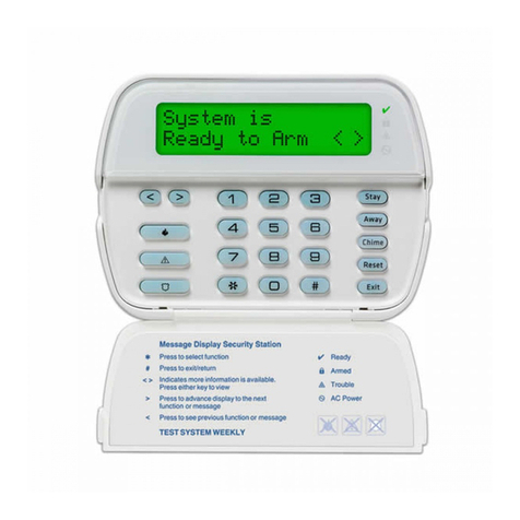
The user interface is simple and easy to use. The PC6501 LCD
keypad guides users through their available options with a series
of questions, which the user can answer with YES or NO. If a
user loses their place in the menu, they can press CANCEL to
return to the start screen.
Users can be assigned to one of four user types: Basic,
Advanced, Supervisor and Master users. Each of the user types
can access different levels of features, as described in section 6
of this manual.
The status of the PC6010 system can be monitored over
telephone lines, or over a dedicated “Backbone” network (see
section 7 “System Operation and Programming”).
You can add access control to the system with PC6820 modules
and readers (see the PC6820 Installation Manual).
The PC6010 main board comes with 2 programmable outputs,
and you can add up to 208 more using PC6204 and PC6216
modules. You can program the outputs to control things such as
doorstrikes, annunciators, and lights, using 56 different output
options (see section 7 “System Operation and Programming”).
You can program the PC6010 using any system keypad, or using
DLS-3 downloading software and a computer (see section 9
“Downloading”).
1.2 Using PC6010 Manuals
Installer Manuals
This manual is for people who will be installing PC6010 systems.
Read the entire manual carefully before beginning your installation.
This manual describes:
• An overview of the system, and the specifications of each
module (see section 2)
• How to install and wire the system and its modules (see
section 3)
• How to program the system (see section 4)
• How to enroll the keypads and modules (see section 5)
• An introduction to the user interface and keypad operation
(see section 6)
• An overview of the main system programming sections (see
section 7)
• How to set up a serial printer to print out system events (see
section 8)
• How to set up the panel for downloading (see section 9)
• How to use the Diagnostics section, reset the system to
factory default settings, and view faults (see section 10).
You should also review the Programming Manual, and
Programming Worksheets:
• The Programming Manual gives detailed descriptions of
each programming section.
• Be sure to record all your system programming in the
Programming Worksheets.
• If you will be adding modules to your PC6010 system, please
read the Installation Instructions that come with each
module.
User Manuals
Two end-user manuals come with the PC6010 system:
• The User’s Guide provides easy to follow instructions for
Basic and Advanced users. Supervisor and Master users can
also refer to this manual for instructions on turning areas on
or off, delaying automatic arming, viewing faults, etc.
• The Maintenance Manual provides instructions on using
more advanced features (e.g. changing access codes) for
Supervisor and Master users.

2
2.1 Overview
Maximum System Capabilities
• Control Unit - 1 PC6010 Main Board
• Up to 256 zones
PC6010 Main Board: 16 zones
PC6108A Expansion Modules: 8 zones each
• 2 Main Board Programmable Outputs (PGM1 & PGM2)
• 1 12 VDC Switched Programmable Auxiliary Power Supply
(Main Board)
• 1 Supervised Programmable Bell/Siren Output (Main Board)
• Up to 64 High Current Programmable Outputs with 16
PC6204 Modules
• Up to 144 Low Current Programmable Outputs with 9
PC6216 Modules
• 1 Serial (Printer) Interface - PC6400
• Up to 64 LCD Keypads - PC6501
• 1 Telephone Interface (Main Board)
• 1 Backbone Interface (using PC6442, PC6443 Modules)
User Interface
• Simple menu structure based on questions, displayed on
PC6501 LCD keypad.
• Four user types available: Basic, Advanced, Supervisor, and
Master
• The menu the user sees is limited to the functions allowed to
their user type
• Utility functions are available to users, such as remote control
doorstrikes and resetting smoke detectors.
256 Programmable Zones
• 16 zones on the main board
• Expand the system to 256 zones using PC6108A expansion
modules
• 19 zone types, including:
• Standard Delay • Auto Verify Fire
• Force Arm Delay • Momentary Arm
• Auxiliary Delay • Maintained Arm
• Instant • 24 Hr Holdup
• Interior • Auxiliary
• 24 Hr Bell • 24 Hr Auxiliary
• 24 Hr Bell/Buzz • 24 Hr Medical
• 24 Hr Buzzer • Seismic
• Standard Fire • LINKS Supervisory
• LINKS Answer
• Zones can be assigned independently to any area, and to any
alarm or seismic group.
Section 2: System Overview
32 Areas
• Separate or shared zones from other areas
• Individual keypads per area
• Individual access codes for each area
• Individual outputs programmable per area
LCD Keypads (PC6501/6501T)
• Total of 64 on the system
• Can be assigned to any area
• User-friendly interface allows fast and simple access to the
system
Access Control (PC6820)
• 16 modules in total - 2 doors per module
• 32 doors total
• Can be used to arm/disarm areas
210 Programmable Outputs
• 2 programmable outputs on the main control panel
• Main board outputs switch to 12VDC, up to 50mA maximum
current draw
• 64 programmable relay outputs - using up to 16 PC6204
Modules
• 144 programmable switched transistor outputs - using up to
9 PC6216 Modules
• Each output can be programmed for 1 of 56 PGM output
options
Switched Auxiliary Output
• Can be programmed for 1 of 56 PGM output options
• 11.6 - 12.6 VDC, 300 mA maximum
Supervised Alarm Output
• Bell Output, 200 mA fused at 5 Amps, 13.8 VDC
• Steady or Pulsed Output
• Can be programmed for 1 of 56 PGM output options
Event Buffer
• Up to 3000 events can be stored in the event buffer
• Each event is logged with a date and time stamp
• System and area events are logged in the event buffer. Area
events are identified by the area label. System events are
identified by the message “System Area”.
• Event Buffer Viewing - Supervisor and Master users can view
2500 events through the keypad, including the date and time
stamp
• Event Buffer Printing - the entire event buffer (3000 events)
can be printed through the Installer’s mode
Internal Memory
• Retains programmed data and system status, even when both
AC and battery have been removed.
• If the panel loses power (indicated by an audible fault beep),
the clock will need to be reset.

3
Communicator
• Communicates using the SIA 1986, or the Contact ID format
• Communicates to up to three telephone numbers
• Each telephone number can be backed up by a LINKS1000
cellular communicator
• With the PC6442 and PC6443 modules, uses the Backbone
to communicate over a dedicated connection with alarm
presentation software. Communications are encrypted.
• One system and 32 area (account) codes
• Hexadecimal numbers available
• DTMF and pulse dialing
• True dial tone detect
Printer
• Can print data on a serial local printer using an PC6400 serial
interface module
Powerful 2.2 amp regulated power supply
• 776 mA auxiliary supply, 11.6 - 12.6 VDC, when charging a
36Ah battery.
• Separately fused for battery, auxiliary supply and bell output
• Electronic shut down protection of the Ebus (Module
Communication Bus)
• Supervision for loss of AC power, low battery, electronic shut
down of modules
• Internal clock locked to AC power frequency or optional
crystal time base
Battery
• 12 volt, 7 to 36Ah minimum rechargeable gel-cell or sealed
lead-acid battery
• Normal battery charging current 360mA
• High battery charging current (1.4A) available (software
selectable)
Transformer
• 16.5 VAC, 80VA
NOTE: 80VA local state electrically approved transformer.
Output Voltage
Typically, with normal AC on and a fully charged battery, the
output voltage will be 13.8 VDC. With AC off and the battery
discharging, the voltage will go below 10 volts and then battery
cutoff will occur preventing further discharge. Devices that
require power from the control panel should be capable of
operation over the voltage range of 10 to 14 VDC.
2 Enclosures
• PC4005C cabinet: PC6010 and two modules
• PC4003C cabinet: 2- PC6108A modules, 1 - PC6204
module, 1- PC6216 module, or 1 PC6400 module
2.2 Module Specifications
Refer to each module’s Installation Instruction sheet for wiring
and programming information.
PC6108A Expansion Module
• 8-zone expansion module
• Add up to 30 modules for a total of 256 zones on the system
• Supports double end-of-line zone loops (5600 ohm resistors)
• Connects to control panel via 4-wire Ebus
• Nominal current draw of 30 mA (from Ebus)
• AUX+ Output: 12 VDC, 250mA max. (power drawn from Ebus)
• Provides Tamper reporting codes
• Low Ebus supervision
PC6204 High-Current Output Module
• 4 high-current outputs
• Output current 1A, 12VDC
• Up to 16 modules on system (up to 64 high-current outputs)
• Each output programmable for 1 of 56 options
• Connects to control panel via 4-wire Ebus
• Low Ebus supervision
• Four programmable relay contacts rated 2A, 30VDC
• Minimum 80 VA 16-18 volt transformer required
• Minimum 4 Ah battery required, up to 36Ah max.
• Current draw: 30 mA (from Ebus)
• Provides Tamper and Trouble reporting codes
• AUX current: 500mA max.
• Tamper contact input
PC6216 Low Current Output Module
• 16-output low-current module
• Nominal current draw of 15 mA, plus power required by
outputs
• Output current 50mA, 12VDC
• Up to 9 modules on system
• Can be programmed as alarm or zone annunciators.
• All 16 outputs can be programmed on each module, 1 of 56
options each
• Provides Tamper reporting codes
• Connects to control panel via 4-wire Ebus
• Low Ebus supervision
• Power drawn from Ebus
PC6400 Serial (Printer) Module
• True RS-232 technology
• Handshake software switches
• DTR Protocol
• Baud rate: 4800
• Connects to control panel via 4-wire Ebus
• Nominal current draw of 35 mA
• Low Ebus supervision
• Tamper and Trouble reporting codes
• Maximum cable length: 200 feet (61 meters)

4
PC6501 Remote Keypad
• Connects to control panel via 4-wire Ebus
• Alphanumeric liquid crystal display
• Built-in piezoelectric buzzer
• Full annunciation of zones and system status
• Dimensions 5.5” x 4.5” x 1” deep (150 x 114 x 25 mm)
• Maximum current draw of 55mA (from Ebus), 90mA with
backlighting boost.
• Up to 64 keypads on system
• Provides Tamper reporting codes
• Low Ebus supervision to main board
PC6820 Access Control Module
Two Zone Inputs
• Two programmable supervised zones ( 5600Ω)
• Zones may be programmed as Standard, Force Arm Delay, or
Auxiliary Delay zone types
• Up to 16 PC6820 can be added (up to 32 access points)
Non Volatile RAM (internal memory)
• Does not lose any system programming when the module is
powered down.
Low Current Outputs
• Six low current outputs (open collector outputs switched to
ground 25mA max.) :
• Two LED terminals - To the LED input of the reader
• Two BUZ terminals - To the buzzer input of the reader
• Two OUT terminals - Reserved for future use
Regulated Power Supply (1.5 Amp max.)
• Electronic shutdown protection of the battery, auxiliary
output, 5 and 12 V reader power supplies, and lock device
power output
• Auxiliary output supply: 12VDC, 125mA Max
• LK1 and LK2 Door Strike power: 12VDC, 250mA Max
• Reader Power 5VDC, 125mA Max
• Reader Power 12VDC, 125mA Max
Reader Technology
• Polaris, Shadow Prox, HID Proximity and 26-bit Standard
Weigand format
Access Card Compatibility
• Polaris POL-C1CN - Polaris Magnetic Cards
• Shadow Prox, Module Numbers:
SH-C1 - Shadow Prox Card
SH-K1 - Shadow Prox Keytag
• HID Proximity:
HID-C1325KSF - Proximity Card
HID-C134KSP - Proximity Keytag
• Weigand - Standard 26 bit formats
Battery
• 12VDC 7.0Ah recommended rechargeable gel-cell
Transformer
• 16.5 VAC, 40VA
Operating Temperature
•2
°
C to 40°C (35°F to 110°F) operational temperature range
•90
°
non-condensing humidity
Output Voltage
• Output voltage = 13.8VDC (with normal AC and a fully
charged battery). Devices that require power from the
PC6820 should be capable of operation over the voltage
range of 10 to 14VDC.
• 5V Power Supply - Devices connected to the 5V supply should
be capable of operation between 4 and 6V.
PC6442, PC6443 Interface Modules
• 1.5Amp power supply
• Outputs for future use
• AUX current: 500mA
• 115 baud RS-232 communications
• Connects to control panel via 3-wire Backbone
• 1 module per system

5
3.1 Planning the System
For a fast and efficient installation of the PC6010, you should
create an installation plan.
As a minimum, use the following checklist to ensure that all of
the details have been considered:
❏Draw a diagram of the installation showing the location of
the main panel, all keypads, all zone inputs, all bell outputs,
all relay outputs and all annunciators.
❏Indicate all areas on the diagram. Decide which zones, bell
and relay outputs, keypads and remote annunciators belong
to each area.
❏Determine where each system module is going to be located
and how far each module will be from the main panel.
❏Determine the current draw on the main panel and each
system component used to ensure the system requirements
can be met (see section 3.4 “Current Ratings – Alarm Control
Panel and Modules”). Calculate each wire run using the Ebus
wiring guidelines. Determine which wire gauge should be
used and where to place PC6204 modules to re-power the
Ebus.
3.2 Out of the Box
Please verify that the following components are included in the
PC6010 package.
❏1 PC4005C cabinet
❏1 PC6010 main control module
❏1 PC6501 LCD keypad
❏1 Hardware package which includes:
❏32 EOL resistors (5600Ω)
❏1 EOL resistors (1000Ω)
❏1 Black cabinet plug
❏1 Green ground strap
❏PCB mounting standoffs
❏1 set of documents which includes:
❏1 PC6010 System Manual
❏1 PC6010 Programming Manual
❏1 PC6010 Programming Worksheets
❏1 PC6010 User Guide
❏1 PC6010 Maintenance Manual
Section 3: Installation and Wiring
3.3 Terminal Descriptions
The following terminals appear on the PC6010 Control Panel:
Terminals Description
Red and Black
Leads
(See section 3.16)
Battery Connection. WARNING: Do not
connect the battery or transformer until
all other wiring is complete.
AC
(See section 3.16)
Power Terminals. WARNING: Connect the
battery before connecting the AC. Do
not connect the battery or transformer
until all other wiring is complete.
AUX+ and AUX-
(See section 3.11)
Auxiliary Power, 376mA MAX
SAUX+
(See section 3.11)
Switched Auxiliary Power, 200mA MAX
BELL+ and BELL-
(See section 3.13)
Bell/Siren Power. These terminals are used for
powering bells, sirens or other devices
requiring steady output voltage on alarm;
200mA MAX
PGM1 and PGM2
(See section 3.10)
Programmable Output Terminals.
50mA MAX (standard output)
Backbone
YEL, GRN, any
COM
(See section 3.7)
Backbone Terminals. The Backbone is used
by the panel to communicate with the
PC6442 and PC6443 modules. YEL and GRN
are used for data. Connect a third wire to
any COM terminal.
Combus
RED, BLK, YEL,
GRN
(See section 3.5)
Combus Terminals. The Combus is used by
the panel and the modules to communicate
with each other (except for the PC644X
modules). RED and BLK are used for power,
and YEL and GRN for data. NOTE: The four
Combus terminals of the main panel must be
connected to the four Combus terminals or
wires of all modules.
Z1 to Z16
(See section 3.8)
Zone Input Terminals. Zone inputs Z1 to Z16
are provided for wiring zones on the alarm
control panel
TIP, RING, T1, R1
(See section 3.12)
Telephone Line Terminals
EGND
(See section 3.14)
Earth Ground Connection. A ground
connection assembly is included with the
control panel.

6
3.4 Current Ratings – Alarm Control
Panel and Modules
In order for the system to operate properly, the power output of
the alarm control panel and power supply modules cannot be
exceeded. Use the data below to ensure that the available
current is not exceeded.
PC6010 Control Panel Current Calculation
At least 100mA must be reserved for the Ebus. To calculate the
amount of current required, complete the following chart:
** See “Ebus Current Calculation Chart” at right.
Module Ratings
The current draws of compatible modules are listed below:
Device .......................................................Current Draw (mA)
Keypad (PC65XX) .................... 43 (105 with backlighting boost)
PC6108A Zone Expander ....................................................... 36
PC6204 Relay Output Module ............................................... 30
PC6216 Low Current Output Module .................................... 30
PC6400 Serial Printer Interface Module ................................. 44
PC644X High Security Interface Module ...............................146
PC6820 Access Control Module .............................................. 2
PC6204 Current Calculation - 2.2Amp Power Supply
** See “Ebus Current Calculation Chart” at right.
NOTE: See the PC6204 Installation Sheet for more information.
PC6820 Current Calculation - 1.5Amp Power Supply
NOTE: See the PC6820 Installation Manual for more information.
PC644X Current Calculation - 1.5Amp Power Supply
NOTE: See the PC644X Installation Sheet for more information.
Calculating Total Current Requirement
Once you have determined which modules will draw power from
the main panel, use the following chart to calculate the Ebus
current.
Ebus Current Calculation Chart
Item Current
(mA)
× Quantity Total (mA)
PC6501 43 or 105 ×
PC6108A*36 ×
*Current required for devices connected to
PC6108A =
PC6204 30 ×
PC6216*30 ×
*Current required for devices connected to
PC6216 =
PC6400 44 ×
PC6820 2 ×
Total Ebus Current =
* These units draw current from the Ebus to power
devices external to the module. This current must be
added to the total Ebus current. See manufacturer's
specifications for the current draw of each device. Each
LED assembly draws up to 20mA of current.
High
Charging
Current
(36Ah
battery)
Low
Charging
Current
(Smaller
battery)
Enter total
current for
each output
here
AUX
Must not
exceed
683mA
Max.
Must not
exceed
1.72A Max.
SAUX+
Ebus**
PGM1 (limited
to 50mA)
PGM2 (limited
to 50mA)
Bell
current draw for
15 minutes
Total:
High
Charging
Current
(36Ah
battery)
Low
Charging
Current
(Smaller
battery)
Enter total
current for
each output
here
AUX Must not
exceed
770mA
Max.
Must not
exceed
1.57A Max.
Ebus**
Relays
Total:
Enter total
current for
each output
here
AUX
Reader 1
Reader 2
LK1 Output
LK2 Output
Total:
(must not exceed 710mA)
Enter total
current for
each output
here
AUX
Outputs
Total:
(must not exceed 634mA)

7
3.5 Ebus Operation and Wiring
The Ebus is used by the control panel and the modules to
communicate with each other. The four Ebus terminals of the
main panel must be connected to the four Ebus terminals or
wires of all modules.
Modules can be home run, connected in a daisy chain or T-
tapped anywhere on the Ebus.
The following rules MUST be followed when wiring the Ebus:
1. The Ebus must be run in minimum 22-gauge wire.
2. No module can be more than 1000' (305m) in cable length
from the main control panel.
3. Shielded wire should only be used in areas that present
excessive RF noise or electromagnetic interference. If shielded
wire is used, the maximum distance a module can be located
from the main panel is significantly reduced. Check the
capacitance limit of the wire to calculate the maximum
distance (see “Capacitance Limits” below).
4. The total capacitance of the Ebus wiring must not exceed
80nF (see “Capacitance Limits” below).
Line Loss
When current is drawn through a piece of wire, voltage will be
lost due to the wire’s resistance. This voltage loss must be
considered for all installations.
To ensure proper operation, at least 12.5VDC must be applied to
all modules on the system (when AC is applied and the battery is
fully charged). If less than 12.5VDC is applied, system operation
will be adversely affected.
To correct the problem, try any or all of the following:
1. Connect a PC6204 power supply near the module to provide
power to the Ebus.
2. Reduce the length of the Ebus run to the module.
3. Increase the gauge of wire.
Capacitance Limits
An increase in capacitance on the Ebus will affect data
transmission and will cause the system to slow down.
Capacitance will increase for every foot of wire added to the
Ebus. The capacitance rating of the wire used will determine the
maximum length of the Ebus.
For example, 22-gauge, non-shielded, 4-conductor wire has a
typical capacitance rating of 20 picofarads per foot (which is 20nF/
1000’). For every 1000' of wire added – regardless of where it is
run – the capacitance of the Ebus will increase by 20nF.
The following chart indicates the total Ebus wire allowed
depending on the capacitance rating of the wire used:
Wire Capacitance per
1000'(300m)
TOTAL Ebus Wire
Length
15nF 5300'/1616m
20nF 4000'/1220m
25nF 3200'/976m
30nF 2666'/810m
35nF 2280'/693m
40nF 2000'/608m
Wires run in parallel also increase Ebus capacitance. For example,
when using 20nF wire, the following would be some of the
combinations allowed:
• Four wire runs at 1000'/305m each
• Six wire runs at 666'/203m each
• Eight wire runs at 500'/152m each
• 10 wire runs at 400'/122m each etc…
NOTE: Contact the wire manufacturer for the capacitance
ratings of the wire being used.
3.6 PC6204 Power Supply
PC6204 power supply modules are required to power additional
modules and devices when the total current from the main panel
is insufficient. A PC6204 should also be used if excessive line loss
is encountered.
PC6204 Current Requirement
AUX - 1.5A available for devices connected to the AUX terminal,
including devices connected to relay outputs and modules
connected for Ebus repower (see section 3.5 “Ebus Operation
and Wiring”).
Ebus Repower
Only Relay 1 on the PC6204 can be used for Ebus repower. The
Ebus must be wired to the PC6204 according to the following
diagram for Ebus repower:
IMPORTANT NOTE: Do not use any power supply other than
the PC6204 to repower the Ebus. In the event of a power surge
or transient, a module may lock up and cease to communicate
with the control panel. If the panel loses communication with
themodule, it willinitiate a module resetand will power down
the Ebus for five seconds in an attempt to reset the problem
module.After five seconds, thepanelwill reapply power tothe
Ebus and the problem module should begin to operate as
intended.
If a power supply other than the PC6204 is used, the Ebus
repower function will not operate as intended.

8
NOTE: New versions of the PC6204 power supply module have
a jumper marked ‘J1’. Ensure that this jumper is configured for
“Ebus Relay.” Otherwise, the power reset function will not
operate. For more information regarding the PC6204, please
refer to the PC6204 Installation Instructions.
3.7 Backbone Operation and Wiring
The Backbone is used by the control panel to communicate with
the PC6442 and PC6443 modules. Connect the BCBK YEL and
GRN terminals, and any COM terminal to the backbone terminals
on the PC6442 and PC6443 modules.
The PC644X modules have independent power supplies and do
not draw power through the Backbone.
Follow the same wiring rules and capacitance limits for wiring
the Backbone, as for wiring the Ebus. Modules can be home run,
connected in a daisy chain or T-tapped anywhere on the
Backbone.
The following rules MUST be followed when wiring the
Backbone:
1. The Backbone must be run in minimum 22-gauge wire.
2. No module can be more than 1000' (305m) in cable length
from the main control panel.
3. Shielded wire should only be used in areas that present
excessive RF noise or electromagnetic interference. If shielded
wire is used, the maximum distance a module can be located
from the main panel is significantly reduced. Check the
capacitance limit of the wire to calculate the maximum
distance (see “Capacitance Limits” below).
4. The total capacitance of the Backbone wiring must not
exceed 80nF (see “Capacitance Limits” below).
Capacitance Limits
An increase in capacitance on the Backbone will affect data
transmission and will cause the system to slow down.
Capacitance will increase for every foot of wire added to the
Backbone. The capacitance rating of the wire used will
determine the maximum length of the Backbone.
For example, 22-gauge, non-shielded, 4-conductor wire has a
typical capacitance rating of 20 picofarads per foot (which is
20nF/1000’). For every 1000' of wire added – regardless of
where it is run – the capacitance of the Backbone will increase
by 20nF.
The following chart indicates the total Backbone wire allowed
depending on the capacitance rating of the wire used:
Wire Capacitance per
1000'(300m)
TOTAL Ebus Wire
Length
15nF 5300'/1616m
20nF 4000'/1220m
25nF 3200'/976m
30nF 2666'/810m
35nF 2280'/693m
40nF 2000'/608m
Wires run in parallel also increase Backbone capacitance. For
example, when using 20nF wire, the following would be some of
the combinations allowed:
• Four wire runs at 1000'/305m each
• Six wire runs at 666'/203m each
• Eight wire runs at 500'/152m each
• 10 wire runs at 400'/122m each etc…
NOTE: Contact the wire manufacturer for the capacitance
ratings of the wire being used.
3.8 Zone Wiring
Zones on the system are wired according to the diagrams below.
Once you have selected which type of zone supervision you
require, you must program the “Zone Supervision” section. See
Section 5.1 “Zone Supervision” for instructions.
NOTE:Fire, LINKS Supervisory, andLINKS Answer zones always
use single EOL supervision, regardless of the programmed
zone supervision (see section 3.9 “Specialized Zone Wiring”).
If the zone is armed and then is violated, the zone will be in
alarm. The system will transmit the alarm, and the bells will
sound until the end of the Bell Time Out, or until silenced by a
user. If the zone is violated again before the first alarm is
cleared, the bells will not re-sound.
No End of Line (No EOL)
All No EOL zones are normally closed loops. The zone will be
violated when it is open.
Single End of Line (EOL)
All Single EOL zones have a 5600Ωresistor across them. If the
zone is shorted or open, it will be violated. Resistors should
always be placed at the device end of the wire run.
If programmed as a fire zone, the open zone will generate a
trouble condition and the short will generate an alarm.
Double End of Line (DEOL)
All Double EOL zones have two 5600Ωresistors across them.
DEOL loops will allow the panel to detect zone faults, zone
tampers, violated zones and restored zones. Resistors should
always be placed at the device end of the wire run. The zone
loop response is 320mS.
NOTE: Only normally closed detection devices can be used
with this type of zone supervision. Only one normally closed
contact can be connected to each zone; multiple detection
9
devices or contacts on one loop are not allowed, as the tamper
condition will not be monitored.
If a tamper or a fault occurs, a buzzer will sound from all
keypads assigned to the area. The buzzer will sound for the
length of the Bell Time Out, or until silenced by a user. The
system will send a zone tamper reporting code to the central
station, if programmed.
NOTE: Zone tampers will not prevent the system from being
armed.
3.9 Specialized Zone Wiring
Some zones require wiring configurations unique to the selected
zone type. These zones are listed below. For information
regarding the various zone types, please see the PC6010
Programming Manual.
Fire Zone
This zone type uses normally open contacts. Standard Fire zones,
and Auto Verify Fire zones must be wired for single end-of-line
supervision. The zone will initiate a fire alarm when the loop is
shorted (contacts close). A Fire Zone trouble will be generated
when the loop is opened (wire break). Typically, fire alarm
initiating contacts originate from 4-wire smoke detectors. These
types of detectors must be wired as shown in the diagram
below.
The power for the 4-wire detectors must be supervised with an
end-of-line relay (RM-1). The contacts of that relay are wired in
series with the zone end-of-line resistor. With the relay
energized, the relay contacts are closed and the zone is normal.
If the power is lost, the relay de-energizes, the contacts open
and a zone trouble is initiated.
Multiple fire initiating normally open contacts may be used in
parallel on the loop. Do not include burglary or other types of
devices on a fire zone.
Keyswitch Zone
Zones programmed as keyswitch arming zones must be wired
according to the following diagram:
LINKS Supervisory Zone
This zone is for use with a LINKS1000/GSM1000 only. If the
LINKS experiences a trouble condition, a LINKS output can be
used to violate this zone type and the event will be reported to
the central station. See the corresponding LINKS1000 or
GSM1000 Installation Manual for wiring information.
LINKS Answer Zone
This zone is for use with a LINKS1000/GSM1000 only. In case of
a telephone line failure, the panel can be uploaded/downloaded
via the cellular network. If the LINKS detects an incoming call, it
will activate an output that can be used to violate this zone type.
This will force the panel to answer the cellular call and will begin
communications with the downloading computer.
This zone must be programmed as LINKS Answer and is wired
according to the following diagram:
3.10 Programmable Output Wiring
The PGM output is a programmable terminal and will connect to
+12V when activated. The terminal can sink a maximum current
of 50mA. If the desired current is higher than 50mA, a relay will
be required. To connect the relay, refer to the diagram below:
Each output can be programmed as one of numerous available
output options. See the “Programmable Output Options”
section in the Programming Manual for a complete list of PGM
output options.

10
3.11 Wiring Powered Devices (AUX,
SAUX+)
AUX (Auxiliary Power)
These terminals can be used to power motion detectors, glass
break detectors and other devices requiring power. The AUX
(positive) and GND (negative) terminals can provide up to 376mA
of current.
SAUX+ (Switched Auxiliary Power)
This terminal provides positive power (12VDC). Typically, this
output is used for providing power to latching type devices that
require a power interruption in order to reset. If the output is
programmed for Sensor Reset (see SW AUX Output in the
Programming Manual), the output will de-energize when a user
answers YES to the “Do You Want to Reset Detectors?” prompt.
The SAUX+ terminal can provide up to 200mA of current.
3.12 Telephone Line Wiring
The telephone terminals provide connections to the incoming
telephone lines for central station reporting. The wires from the
RJ31-X jack must be connected in the following manner:
NOTE: For proper operation,theremustbe no other telephone
equipment connected between the control panel and the
incoming telephone line (e.g. answering machines, fax
machines, telephones, etc.).
3.13 Bell Output Wiring (BELL+and BELL-)
These terminals are used for powering bells, sirens or other
devices requiring steady output voltage on alarm. The panel can
provide up to 2A short-term or 200mA (for 15 minutes) current.
The output is supervised. A trouble condition will be generated
when the bell connection is lost. If no bell or siren is being used,
connect a 1000Ωresistor across the BELL+ and BELL- terminals
to eliminate a trouble condition.
To ensure proper operation, the wire length of the bell loop
must be considered.
Consult the following chart to determine the maximum wire
length for the bell loop with respect to current. The values reflect
the use of a 30 watt siren.
Distance to last bell/siren (ft/m)
Bell Loop
Load
Current
22 AWG
Wire
20 AWG
Wire
18 AWG
Wire
16 AWG
Wire
14 AWG
Wire
2000mA 18/6 29/9 46/14 73/22 116/35
1800mA 20/6 32/10 51/16 81/25 129/39
1000mA 36/11 58/17 92/28 147/44 233/70
700mA 52/16 82/25 132/40 210/64 332/101
500mA 73/22 115/35 184/56 293/89 465/141
100mA 364/110 577/175 922/279 1467/445 2326/705
To increase the length, double up on wire. For example, when
using 22-gauge quad, use two conductors for the Bell+
connection and two for the Bell-. This effectively doubles the
maximum distance.
3.14 Earth Ground Wiring
The cabinet should be earth grounded using the grounding
connector, as described in local rules and regulations. In the
U.K., the connection shall meet the applicable requirements of
BS6701, part 1, section 6.10.
The EGND terminal must be connected to earth ground.
3.15 Mounting the Cabinet, Control
Panel and Modules
There is room in the PC4005C cabinet for the main control panel
and two modules. A small expander cabinet (PC4003C) is available
for a single module that does not require external power.
1. Select a dry location close to an unswitched AC source, a
round connection and a telephone connection for mounting
the Main Control Cabinet.
2. Remove the PC6010 printed circuit board, mounting
hardware, and keypad from the cardboard retainer inside the
large cabinet.
3. Before attaching the cabinet to the wall, press the five white
nylon printed circuit board mounting studs into the cabinet
from the back.
4. Pull all cables into the cabinet and prepare them for connection
before mounting the circuit board to the back of the cabinet.
Press the circuit board down onto the mounting studs.

11
5. Once you have made all the proper connections, you can
apply power to the system. First connect the battery, then the
AC transformer. See section 3.16 below, for more
information.
3.16 Applying Power (AC and Battery)
WARNING:Do not connect thebattery or transformeruntil all
other wiring is complete.
NOTE:80VA local state electrically approved transformer.
Once all field wiring has been completed and checked for opens,
shorts and grounds, power can be applied to the panel as
follows:
1. Connect the battery leads.
2. Connect the AC transformer.
The panel will not power up correctly if AC power is applied
before the battery is connected.
After you apply power to the system, for the first 2 minutes, the
system will consider all zones as non-violated. This is to allow
time for the detectors to “settle”, preventing false alarms.
Battery Selection Charts
The charts below are to determine the battery required to
support the main panel for either 24 hours or 60 hours in the
standby mode. The battery size is measured in amp hours (Ah).
To determine the appropriate battery size, perform the
following:
1. Calculate the total current required when the panel is not in
alarm. This is the standby current. See section 3.4 for further
information on current calculation.
2. Determine the current that will be drawn when the panel is
in alarm.
3. On the chart below, find the standby current on the
horizontal axis and the alarm current on the vertical axis.
4. Find the region of the chart where the standby current and
the alarm current values intersect. The region corresponds to
the required battery Ah capacity.
You can select the battery charging current in the System Toggle
Options section. To have the charging current set at 1.4A, turn
on the Hi Batt Charg option. If the option is off, the battery
charging current will be 360mA. See the Programming Manual
for more information.
For example:
Standby current = 500 mA
Alarm current = 2 A
On the 24Hr chart, the battery capacity required is 14Ah.
Battery Connection – Red and Black Battery
Leads
Connect the red battery lead to the positive terminal of the
battery and the black lead to the negative terminal.
WARNING: Observe the correct polarity. If the battery is
connected backwards, the panel will not operate.
AC Power Terminals
WARNING: Connect the battery before connecting the AC
power.
A 16.5V, 80VA transformer connected to an unswitched AC
power source should be wired to these terminals.
To achieve the rated outputs as previously described, the AC
input must be connected to the secondary of a transformer rated
at 16 VAC, 80VA minimum.
Do not connect the transformer primary to an outlet that is
controlled by a switch.
The PC6010 monitors the presence of AC power on all modules
on the system. The Power light on the keypad will always be on
while AC power is on. Upon the loss of AC power, the system
generates a trouble condition. If an AC trouble occurs on any
component of the system, the Power light will turn off. The AC
Fail Delay does not affect the Power light - it will turn off as soon
as there is an AC trouble on any module on the system. The
Power light will turn back on only when AC is physically restored
to all system components. AC and Battery troubles will not
prevent arming of the system.
3.17 Lithium Batteries
The PC6010 circuit board includes a lithium battery. (Please see
the wiring diagram on page 24.) This battery is not replaceable.
There is a danger of explosion if the battery is incorrectly
replaced.
If the lithium battery stops working, return the circuit board to
DSC Ltd. Batteries may cause a fire when in contact with metal.
If you need to dispose of the circuit board and/or the lithium
battery, wrap the battery in non-conductive tape. Check with
your local government for battery disposal regulations.
WARNING: Do not store the batteries in such a way that they
come into contact with each other or with any piece of metal.
Explosion or fire may occur. Should fire occur, use only dry
chemical fire extinguishers. Do not use water to put out the
fire. Do not heat the batteries. Do not dispose of the batteries
or circuit boards in a fire. Do not disassemble the batteries. Do
not apply pressure to or deform the batteries. Ensure that the
aboveprecautionsarestrictlyobservedbyrelateddepartments,
including, but not limited to, production, sales and outside
contractors.

12
4.1 Enrolling Keypads and Modules
Once you have completed the wiring of all keypads and
modules, they must be enrolled on the system.
Apply power to the system by first connecting the battery,
followed by the AC transformer (see section 3.16). All LCD
keypads will display the message “PC6501 DSC Ltd.”
NOTE:Make sureallpowerto thesystemisOFF whenconnecting
any modules.
NOTE: Record the location and the number of each module in
the Programming Worksheets for future reference.
4.2 Enrolling the First Keypad
To enroll the first keypad, go to the keypad that is to be
assigned to area 1. Press any key on that keypad.
The keypad beeps and displays the message “65XX Mod. #1.”
This keypad is automatically enrolled and assigned to area 1.
Once you have enrolled the first keypad, you can enroll the rest
of the system keypads and modules through the “Module
Hardware” section of installer’s programming.
4.3 Enrolling All Other Keypads
At the keypad you have just enrolled:
1. Enter installer’s programming by pressing [*] [8] [Installer’s
Code].
NOTE: The default installer’s code is [5555].
2. Use the arrow keys (<>) to scroll to “Module Hardware”.
Press the [*] key.
3. The keypad displays the message “Enroll Module”. Press [*].
4. Scroll through the module types, until the PC6501 keypad is
displayed. Press the [*] key.
5. The keypad will display the message “Press Any Key On
Desired Unit.” Go to the keypad to be enrolled and press any
key.
6. Return to the original keypad. A message similar to the
following will confirm enrollment of the keypad:
“PC65XX Mod 02 Enrolled”
7. Next, you must select which area the keypad will control. Use
the arrow keys (< >) to scroll to the desired area. Press the [*]
key to select the area. If you press the [#] key, the keypad will
be assigned to Area 1 by default.
NOTE: To change the area to which a keypad is assigned, you
must delete, and then re-enroll the keypad.
8. Make sure you record the module number and assigned
areas of all keypads on the Programming Worksheets.
4.4 Enrolling PC6108A, PC6204,
PC6216, PC6400, and PC6820
Modules
At any enrolled keypad:
1. Enter installer’s programming by pressing [*] [8] [Installer’s
Code].
2. Scroll to “Module Hardware” and press the [*] key.
3. The keypad displays the message “Enroll Module”. Press the
[*] key.
4. Scroll through the module types, until the module you wish
to enroll is displayed. Press the [*] key.
5. The keypad displays the message “Create Tamper On Desired
Unit”. To enroll the module, you will need to create a tamper
condition on it. To create the required tamper, secure the
tamper zone on the module, and then open the tamper zone.
It is the transition from secure to violated which enrolls the
module.
6. After the module has been tampered, the keypad displays the
module number and confirms enrollment (e.g. “PC6204 Mod
01 Enrolled”). Record the module number in the
Programming Worksheets.
7. Once the module is enrolled, re-secure the tamper.
Enrolling Zone Expanders
NOTE: Enroll all zone expanders before assigning zones to
PC6820 modules.
Zones 001 to 016 are located on the main control panel.
Additional zones are added in sequence. For example, if you
enroll two PC6108A zone expanders, the first one will be
assigned zones 017 to 024, and the second will be assigned
zones 025 to 032.
The system can have a maximum of 256 zones. To confirm which
zones are assigned to which expander, press any key when the
keypad displays the enrollment confirmation message.
NOTE: Be sure to record the zones assigned to each zone
expander module in the System Overview section of the
Programming Worksheets.
Section 4: Module Enrollment

13
4.5 Enrolling PC6442 and PC6443
Modules
Before you can enroll any PC644X module, you must program
the Originator ID to be [01]. After the Originator ID is changed to
[01], you will be able to access all of the Backbone programming
sections. See “Backbone Section” in the Programming Manual,
for more information. At any enrolled keypad, do the following:
1. Enter installer’s programming by pressing [*] [8] [Installer’s
Code].
2. Scroll to “Backbone Section” and press the [*] key.
3. Scroll to “Originator ID” and press the [*] key. Program [01]
in this section.
4. Press [*], then scroll to “Module Hardware” and press the [*]
key.
5. Scroll to “Backbone Modules”. Press the [*] key.
6. The keypad displays the message “Enroll Module”. Press the
[*] key.
7. Scroll through the module types, until the module you wish
to enroll is displayed. Press the [*] key.
8. The keypad will display the message “Create Tamper On
Desired Unit”. To enroll the module, you will need to create a
tamper condition on it. To create the required tamper, secure
the tamper zone on the module, and then open the tamper
zone. It is the transition from secure to violated which enrolls
the module.
9. After the module has been tampered, the keypad displays
the module number and confirms enrollment (e.g. “PC6442
Mod 01 Enrolled”).
10.Once the module is enrolled, re-secure the tamper.
4.6 Deleting Modules
Sometimes, a module must be deleted from the system. This
could be when zone expanders are enrolled out of sequence, a
keypad is assigned to the wrong area, or if a module is defective.
If you need to disconnect a module from the control panel, be
sure to first delete it from the system.
To delete a module, enter the following at any enrolled keypad:
1. Enter installer’s programming by pressing [*] [8] [Installer’s
Code].
2. Scroll to and select the Module Hardware > Delete Module
programming sections.
NOTE: To delete a backbone module, you will need to select
Module Hardware > Backbone Modules > Delete Module.
3. Scroll through the module types until you see the module
you wish to delete. Press [*] to select.
4. Scroll to the correct module number. For example, to delete
PC6501 Module 04, scroll to “PC6501 (04).”
5. To delete the module, press the [*] key.
NOTE: When you delete and/or replace zone expanders, you
shouldre-enroll all remainingzone expanders. This willensure
proper zone assignment and operation.
4.7 Confirming Modules
If the module numbers were not recorded in the Worksheets,
you can check this information through the “Confirm Module”
menu.
The procedure for confirming modules is similar to the
procedure for enrolling them.
1. Enter installer’s programming by pressing [*] [8] [Installer’s
Code].
2. Scroll to and select the Module Hardware > Confirm Module
programming sections.
NOTE: To confirm a backbone module, you will need to select
Module Hardware > Backbone Modules > Confirm Module.
3. Scroll through the module types, until the module you wish
to enroll is displayed. Press the [*] key.
4. You will be prompted to “Press Any Key On Desired Unit” in
the case of keypads, or to “Create Tamper on Desired Unit”
in the case of modules.
5. Once you have pressed a key (on the keypad), or created a
tamper (on the module), the keypad displays the module
number (e.g. PC6501 Mod 02). Be sure that is it recorded
correctly on the Programming Worksheets.

14
5.1 Introduction to Programming
You can use two methods to program the PC6010:
• using the menu system on any system keypad
• using a computer and DLS-3 downloading software.
This section describes how to program the system using a
keypad and the menu system. For more information on
programming using downloading software, see section 10
“Downloading”, and the DLS-3 manual.
Programming From a Keypad
To program the PC6010 using the menu system, you must have
installed and enrolled at least one keypad. See section 4 for
more information.
1. To program the system, you will first need to enter the
Installer’s Programming mode: enter [*][8][Installer’s Code] at
any keypad that is enrolled on the system.
By default, the Installer’s Code is [5555]. When you are in
Installer’s Programming, all LEDs on the keypad will be off.
To prevent unauthorized personnel from entering Installer’s
Programming, you should change the Installer’s Code from
the default setting. For more information, see “System
Section - Installer Options” in the Programming Manual.
2. To navigate through the menus, use the arrow keys (<>).
When you see the menu item you want, press the [*] key to
select it. Getting to the right programming section may
require scrolling and selecting items from several menus. To
return to previous menus, press [#].
Refer to the Programming Manual for an overview of the
menu structure, and descriptions of each programming
section.
NOTE: The YES, NO and CANCEL buttons do not work in
Installer’s Programming. If you press them in Installer’s
Programming, the keypad will sound an error tone.
3. Once you have entered Installer’s Programming, the first
menu consists of the items listed below. Use the arrow keys
(< >) to scroll to the area you wish to program, and press [*].
System Area - Use this section to program options that
affect the operation of the entire system. These options
include communications, downloading, printer options,
installer and master code programming, etc.
Area Section - Use this section to program options for each
area. These options include zone assignments, area times,
area options, etc.
Backbone Section - Use this section to program options for
the Backbone.
Module Hardware - Use this menu to enroll the system
modules and keypads.
Event Buffer - Use this menu to print the event buffer for
the system.
Diagnostics - Use this menu to find out more information on
trouble conditions reported by the modules.
Example: to program the Area 2 ID code, scroll to each of
the following messages, and press [*]:
Scroll to... AREA SECTIONAREA SECTION
AREA SECTIONAREA SECTION
AREA SECTION Press [*]
Display shows... ADD/EDIT AREAADD/EDIT AREA
ADD/EDIT AREAADD/EDIT AREA
ADD/EDIT AREA Press [*]
Display shows... “AREA 1”“AREA 1”
“AREA 1”“AREA 1”
“AREA 1”
Scroll to... “AREA 2”“AREA 2”
“AREA 2”“AREA 2”
“AREA 2” Press [*]
Display shows... AREA ID CODEAREA ID CODE
AREA ID CODEAREA ID CODE
AREA ID CODE Press [*].
Enter the 6-digit Area 2 ID code. The display returns to the
message “Area ID Code”.
Press [#] to return to the previous menus, and to exit the
installer programming mode.
NOTE: The [#] key is not a cancel key. If you have entered data
in a section, and then press [#], the data will be saved.
5.2 Programming Using Hotkey
Numbers
Another method of navigating through the menus uses one- or
two-digit hotkey entries. Every menu and program item has a
“hotkey” entry. You can find the hotkey entry for any section in
the Programming Worksheets.
The hotkey entry for each programming section is displayed on
the LCD screen. Enter that number, and the panel will select the
item for you. Do not press [*] after entering the ‘hotkey’
number.
For example, once you have entered Installer’s Programming, you
can reach the Area 2 ID code programming section by entering:
[1]-[0]-[02]-[0]
Once you become familiar with the menus, the hotkey method
will allow you to move quickly through the menus.
To exit a section or move back a menu, you can press [#]. To exit
Installer’s Programming, you may have to press [#] several times,
depending on where you were in the menu system.
NOTE: The [#] key is not a cancel key. If you have entered data
in a section, and then press [#], the data will be saved.
Once you become familiar with each programming option’s
hotkey number, programming will become quick and simple. If
you lose your place, you can always use the [<][>] keys to scroll
through the menu items, and refresh your memory.
5.3 Programming Decimal Data
Some programming sections require decimal (0-9) entries, such
as zone definitions and system times. Make sure that you record
all required decimal data in the Programming Worksheets before
beginning to program each section.
Many sections require a specific number of digits. Once all digits
have been entered, the control panel will automatically exit that
section and will return to the previous menu.
Section 5: Programming the PC6010

15
If you press the [#] key, only the data that you entered will be
changed. All remaining programming data will be left
unchanged. For example, when programming telephone
numbers you do not need to program all 32 digits. When you
have finished entering the telephone number, press [#] - the
telephone number will be saved and the system will exit from the
programming section. .
5.4 Programming Hexadecimal Data
Hexadecimal or “Hex” digits are often required for programming
items, such as telephone numbers and reporting codes. To insert
a Hex digit into a programming section:
1. Press [*] to enter the Hex menu.
2. Use the arrow keys to scroll through the each Hex digits (A
through F).
3. When the desired letter is displayed, press [*] again.
You can also enter Hex digits by pressing [*], followed by the
number which corresponds to the Hex letter (A = 1, B = 2, C = 3,
D = 5, E = 5, F = 6). Once the digit is entered, the control panel
will automatically return to the decimal programming mode.
For example, to enter “ABCD”, you would press: [*], [1], [*], [2],
[*], [3], [*], [4]
5.5 Programming Toggle Options
Many programming items are toggle options that are either
enabled or disabled. Use the arrow keys (< >) to scroll through
the toggle options. Press [*] to switch back and forth between
[Y]es (enabled) and [N]o (disabled). Once all the toggle options
have been programmed, press [#] to save your changes, and
return to the previous menu.

16
6.1 Introduction
The PC6501 liquid crystal display
(LCD) keypad guides users through
each operation with easy-to-
understand prompts. The keypad
beeps once each time a key is pressed.
With unique sound sequences, the
keypad can also signal faults and
other indications of system status.
For each feature, the system will
display a question (e.g.. Do you want
to turn areas on?). Users can press YES
to answer yes, or NO to answer no. If users are unsure, or have lost
their place in the system programming, they can press CANCEL to
return to the start screen.
If no key is pressed on the keypad for 60 seconds, it will return
to the start screen, for example:
12:00 2000/01/01
Enter Your Code
NOTE: The YES, NO and CANCEL buttons do not work in
Installer’s Programming. If you press them in Installer’s
Programming, the keypad will sound an error tone.
In the user menus and manuals, arming is referred to as “turning
the system on”, and disarming is referred to as “turning the
system off”.
In the “Turn Areas On/Off” and the “View System Status” user
menus, when you scroll to an area the On and Off lights will
display the current status of the area. For example, at the prompt
“Turn ON Area? Area 1”, if area 1 is currently off, the Off light
will be lit. The On and Off lights will not be lit at other times.
The Power light will always be on, unless there is an AC power
fault.
Refer to the PC6010 User’s Guide and Maintenance Manual for
detailed information about end-user functions. Users of the
system should read the appropriate manual carefully to become
familiar with the features that have been implemented on the
system. Make sure that all users of the system are instructed in
its use.
6.2 User Types
The PC6010 system can have up to 1000 users programmed.
Users can be assigned to one of four user types: Basic,
Advanced, Supervisor and Master users. Each of the 4 user types
can access different levels of features, as described below. For
instructions on programming user codes and cards, please refer
to the PC6010 Maintenance Manual.
Section 6: Keypad Operation and User Types
User Types: Basic Advanced Supervisor Master
Arm (Assigned Areas) YY Y Y
Disarm (Assigned Areas) YY Y Y
Silence Siren/Bell (Assigned
Areas) YY Y Y
View Alarms (Assigned
Areas) YY Y Y
Acknowledge/Clear Alarms
(Assigned Areas) YY Y Y
View Open Zones (Assigned
Areas) YY Y Y
Bypass/Disable Zones on
Arming (Assigned Areas) YY Y Y
View and Clear Basic Faults YN N N
View and Clear Advanced
Faults NY Y Y
Delay Automatic Arming YY Y Y
Activate Doorstrike NY Y Y
Reset Detectors NY Y Y
Cancel Automatic Arming NNYY
View Event Buffer/Log NNYY
Bypass and Disable Zones (All
Areas, at Any Time) N N NY
View System Status (All
Areas) N N NY
Change Access Codes (Only
Codes in a Lower User Type) NNYY
Change Keypad Setup NNYY
Change Time & Date N N NY
Perform System Test N N NY
Allow System Service N N NY

17
6.3 “Warning - Security Reduced”
Messages
These messages are displayed on the keypad if a user tries to
arm the system when there is a problem with one or more zones
(i.e. a zone is open, in alarm, or has a fault, tamper, seismic fault
or trouble condition).
The following message will be displayed on the keypad:
“Warning - Security Reduced”
If this message is displayed, users can continue arming their
area(s) by pressing the YES button. The keypad then displays
“Warning Confirmed”, and the area(s) are armed.
6.4 Time and Date Display
When the keypad is idle, it will show the time and date. The
clock will show in 24-hour time (00:00 - 23:59), and the date
will show as year/month/day (YY/MM/DD). For example, 1:30 pm
December 13, 1999 will be displayed as 13:30 1999/12/13
The system will automatically adjust for the switch to daylight
savings time in March, and back to standard time in October.
The dates that these changes occur on are programmed in the
Daylight Savings and Standard Time programming sections. See
System Times in the PC6010 Programming Manual for more
information.
If the system is connected to Alarm Presentation Software over
the backbone, the system will get the new time from the
software, and will not follow the Daylight Savings Time /
Standard Time programming sections.
Master users also can reset the time and date through the user
interface. See the Maintenance Manual for more information.
6.5 Keypad Lockout
After a programmed number of incorrect attempts to enter a
user or installer’s code, the keypad will lock out the user. The
lockout prevents the user from performing any function at any
keypad.
The keypad will display “Keypad Lockout is Active” for the
lockout duration. See the “System Options” section in the
Programming Manual for information on programming the
number of incorrect code entries allowed (Total Bad Codes), and
how long the keypad will remain locked out (Lockout Duration).
6.6 Keypad Tampers
If there are tamper plates attached to the PC6501 keypad, you
should enable the Keypad Tampers toggle option. See the
“System Options” section in the Programming Manual.
6.7 Keypad Backlighting
When a user presses a key on the keypad, the keypad
backlighting will increase to the “boost” level. After 30 seconds
of inactivity, the keypad will return to the preset backlight level.
Master and Supervisor users can select the level of (non-boosted)
backlighting in the Keypad Setup section of the user menu.

18
When users answer YES to “Do you want to reset detectors?”,
outputs programmed for Sensor Reset will de-activate for the
Utility/Sensor PGM pulse time, so that the connected sensors will
be reset.
Event Schedules
You can program schedules for the communication of openings
and closings, automatic arming and disarming, access control,
and the activation of programmable outputs in the Event
Scheduling section. See the Programming Manual for a detailed
description.
Access Control
If you connect one or more PC6820 modules to the PC6010
system, you can program the system to control access to up to
32 separate doors. See “6820 Options” in the Programming
Manual, and the PC6820 Installation Manual for detailed
information.
7.2 Area Programming
An area is a group of zones which can be armed and disarmed
together. Up to 32 separate areas can be programmed on the
PC6010.
Most of the programming for individual areas is in the Area
Section. To program an area, you must first enable it in the Add/
Edit Areas section. Area 1 is enabled by default.
To enable and program an area:
1. Enter Installer’s Programming ([*][8][Installer’s Code]).
2. Scroll to Area Section, then press [*].
3. Scroll to Add/Edit Area, then press [*].
4. Scroll to the area you want to enable and program, then press
[*].
Assigning Zones to Areas
Each zone must be assigned to at least one area. To assign zones
to an area, select an area to program in Area programming, and
go to the Zone Assignment section.
Assigning Users to Areas
Each user must be assigned to each area they will have access to.
Supervisor and Master users can assign users to areas in Access
Code programming in the user menu. See the Maintenance
Manual for more information.
Programming the Area Arm/Disarm Mask
The Arm/Disarm Mask for areas is in the System Options section.
Areas toggled to NO in the mask cannot be armed or disarmed
from a keypad. Areas toggled to NO in the mask, can only be
armed by access control, automatic arming, keyswitch arming,
via the APS/ODS, or via the DLS-3 software. This may be useful if
an area contains only an entryway, with the keypad outside the
area. If a user were to arm all their areas, including the entryway,
they may cause a false alarm when they exit (or enter) through
the area. By default, all areas are set to YES, and can all be
armed from area keypads.
Programming Area ID Codes
Program an Area ID Code so that the central station will be able
to identify the area. Select area-specific features (such as bell
squawk , entry and exit delay, and autoarm settings) in the Area
Section 7: System Operation and Programming
Once you install all the modules and devices and enroll them on
the system, you will need to program the system so that it works
correctly. Review this section for an overview of how the system
works, and for descriptions of the main programming areas.
7.1 System Programming
Programming options which affect the operation of the entire
system are in the System Area:
Installer and System Options
You can change the Installer and Walk Test codes in the Installer
Options section. The System Reset feature is also in this section.
System toggle options, keypad lockout options, system times,
and the arm/disarm mask for areas are in the System Options
section. See the Programming Manual for a complete description
of these sections.
Downloading
You can program the PC6010 remotely using a computer and
DLS-3 downloading software. Refer to the DLS-3 manual for
more information. See section 9 “Downloading” for information
on setting up the PC6010 for downloading. See the DLS section
of the Programming Manual for descriptions of the PC6010
programming sections related to downloading.
Communications
You can choose to use either the SIA FSK or Contact ID
communications format for land line communications. You can
either program each reporting code that you will use in the
“Communicator” programming section, or use the automatic
reporting code feature available for both formats.
Please refer to the “Communicator” section of the Programming
Manual, for descriptions of the available reporting codes, and
descriptions of communication programming options. Refer to
Appendix B of the Programming Manual for a list of
recommended Contact ID codes, and the SIA automatically
generated reporting codes.
LINKS1000 Programming
The LINKS1000 Cellular Communicator can be used to back up
all three telephone numbers. You can also use the LINKS1000 as
a primary or backup communicator for downloading.
Please see the “LINKS Module” section of the Programming
Manual for more information on LINKS1000 programming.
Programmable Outputs
Programmable outputs are terminals on the PC6010 board, or
on PC6204, PC6216 modules which can control connected
devices according to various programming options.
For example, you could connect PGM1 on the main board to a
bell. If you program PGM1 as output option (12) Chime
Follower, the system will turn on the bell whenever the door
chime is activated on the selected areas.
You can program options for programmable outputs in the PGM
Outputs section. See the Programming Manual for a detailed
description of each output option.
User-controlled Outputs
When users answer YES to “Activate door strike?”, outputs
programmed for Utility Output will activate for the Utility/Sensor
PGM pulse time.
Other manuals for Maxsys PC6010
4
Table of contents
Other DSC Security System manuals

DSC
DSC LCD4500 User manual

DSC
DSC PowerSeries Neo HS2128 E User manual

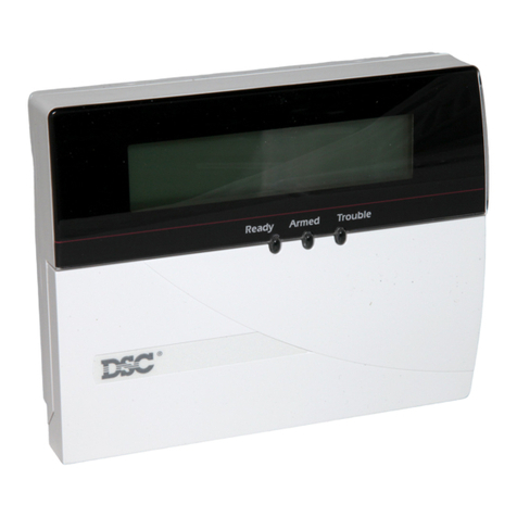
DSC
DSC PC550 User manual

DSC
DSC MAXSYS PC4020 User manual

DSC
DSC PowerSeries Neo HS2064 E User manual

DSC
DSC Voice Assisted Security Control Escort 4580 User manual

DSC
DSC PC 5010 User manual

DSC
DSC PC 4010 Owner's manual

DSC
DSC Envoy NT9005 User manual

DSC
DSC PC2550 User manual