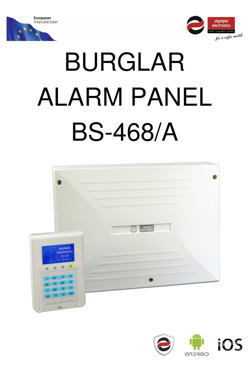
olympia electronics BS-468/A User manual

BURGLAR
ALARM PANEL
BS-468/A

2
Contents
1.
Description ............................................................................................................................... 4
2.
User instructions ...................................................................................................................... 5
2.1.
Basic operations .................................................................................................................. 5
omplete System ..................................................................................................................................... 5
Split System ............................................................................................................................................. 5
2.2.
Armed system indication ...................................................................................................... 6
2.3.
Advanced operations ........................................................................................................... 6
2.4.
Main User menu .................................................................................................................. 8
3.
Installation instructions ......................................................................................................... 13
3.1.
Quick installation guide ...................................................................................................... 13
3.2.
onnections ...................................................................................................................... 16
onnecting the battery and the mains power supply ................................................................................ 16
Keyboard connections ............................................................................................................................ 16
Siren connections ................................................................................................................................... 18
Zone connections ................................................................................................................................... 19
onnection of smoke and heat detectors ................................................................................................. 20
3.3.
Programming through the keyboard ................................................................................... 20
Panel programming as TE HNI IAN ...................................................................................................... 21
Programming passwords functions .......................................................................................................... 22
General settings ..................................................................................................................................... 23
Automatic arming-disarming.................................................................................................................... 24
Zone Programming ................................................................................................................................. 25
Wired zones status ................................................................................................................................. 27
Outputs programming ............................................................................................................................. 27
System general parameters programming ............................................................................................... 28
BS-465 PSTN telephone dialer programming .......................................................................................... 29
BS-464 GSM telephone dialer programming ............................................................................................ 31
Wireless Network ................................................................................................................................... 33
Factory Menu ......................................................................................................................................... 34
3.4.
Wireless Zones Functions .................................................................................................. 35
Wireless Zones Extension Board Installation ........................................................................................... 35
Wireless devices installation ................................................................................................................... 35
Wireless devices deletion........................................................................................................................ 37
General information concerning wireless devices installation procedure ................................................... 38
Wireless Zones Events ........................................................................................................................... 38
Wireless devices types ........................................................................................................................... 39
3.5.
Resetting to factory default passwords ............................................................................... 41
3.6.
Programming from the computer ........................................................................................ 41
Online Operation .................................................................................................................................... 42
"Panel" Window ...................................................................................................................................... 45
"Zones" Window ..................................................................................................................................... 45
" odes" Window ..................................................................................................................................... 47
"Events" Window .................................................................................................................................... 48
"Timers" Window .................................................................................................................................... 50
"Outputs" Window................................................................................................................................... 50
"Wireless" window .................................................................................................................................. 51
"Wireless Info" Window ........................................................................................................................... 52
"GSM " Window ...................................................................................................................................... 52
"PSTN" Window ..................................................................................................................................... 53
Master and Technician user password modification ................................................................................. 54
hange application language .................................................................................................................. 54
3
Load settings from a file ..........................................................................................................................55
Save settings to a file ..............................................................................................................................55
Send settings to the panel .......................................................................................................................55
Offline onnection ..................................................................................................................................56
New .......................................................................................................................................................56
Panel's Firmware Update ........................................................................................................................57
4.
I - OLYMPIA APPLICATIO ....................................................................................................58
5.
Technical Characteristics .......................................................................................................59
5.1.
Peripheral device consumption chart ..................................................................................60
6.
Information regarding the installation ...................................................................................61

4
1. Description
The BS-468/A is an 8 zone burglar alarm panel. Using the special expansion card BS-469 it can be
expanded to 16 zones. Using the special expansion card BS-479, the panel acquires 32 wireless
zones. For its operation, at least one BS-466 keyboard is required. Up-to 8 keyboards can be con-
nected to the panel. Each keyboard has an additional zone for connecting magnetic contacts (zones
17–24). The main board of the panel has port for connecting an YET-205B-630 remote control receiv-
er and an automatic telephone dialler. On the telephone dialler port you can connect a BS-465 wired
PSTN telephone dialer or a BS-464 wireless GSM telephone dialer.
The diagram below shows the interior of the panel and the keyboard.
USB port for panel control
Indication LEDs
onstantly lit means that there is an error,
blinking means that there is an alarm
Α System fully armed
Β System partially armed
The panel power cord is connected
Control keypad
0-9: numbers
“ * ” : Enter button
“ #
ES
”: ES button
A,B, ,AB : Instant Arming without code
+ AB : Panic signal
Liquid crystal display

5
2. User instructions
2.1. Basic operations
The panel has 1 main code (master code) which by default is set to [1 2 3 4] and up-to 50 user codes
which by default are not programmed. The system can operate in two different modes. Depending on
the mode of operation, the arm and disarm operations differ.
Complete System
In this case the system arms and disarms altogether.
Arming can be achieved by using the master code or one of the user codes. The arming of the sys-
tem can also be done by simply pressing the AB key during the installation if the option «ARM
WITHOUT ODE» has been selected.
Disarming can be achieved by entering the master code or one of the user codes.
Split System
In this case the system operates as three independent subsystems. You can arm and disarm the
whole system or each subsystem independent from the others.
Arming of the whole system can be done by using the master code or one of the user codes that
have been programmed for general arming. The arming of the system can also be done by simply
pressing the AB key if during the programming the option «ARM WITHOUT ODE» has been se-
lected.
The disarming of the system can be done by using the master code or one of the user code that
have been programmed for general disarming.
The individual arming of the subsystems Α, Β, C can be done by pressing one of the user codes
that have been programmed to arm each subsystem. The arming can also be done by pressing one of
the Α, Β or keys if during the programming « ARM WITHOUT ODE » has been selected. The arm-
ing of one subsystem does not affect the status (armed-disarmed) of the other subsystems.
The individual disarming of the subsystems Α, Β, C can be done by pressing one of the user
codes that have been programmed to disarm each subsystem. The arming of one subsystem does not
affect the status (armed-disarmed) of the other subsystems.
If during the arming procedure a zone is active then the keyboard show the message:
Which means that on zone 5(kitchen) a window has been left open.
If we press (#) the arm command is canceled.
If we press (*) or close the kitchen window we see:
This message is shown for 1 second and immediately the arming
process starts.
SYSTEM CAN NOT ARM
ZONE 05
KITCHEN
*: BYPASS ZONE
#: CANCEL
ZONES BYPASSED
READY TO ARM

6
2.2. Armed system indication
When the system is armed, then next to the clock, instead of the
Olympia electronics logo there is a lock symbol. Next to the lock
symbol we can see which sections are armed. In this example we
can see that the system is partially armed because only the
section is armed. If the system was fully armed then the symbols
Α, Β, would have been displayed. When the system is dis-
armed then the lock is removed and the Olympia electronics logo
is displayed.
2.3. Advanced operations
By pressing the " * " key the display shows:
Using the up and down keys (keys 2 and 8), we can move the cur-
sor upward or downward. By using the " * " key we can achieve
the required selection. By using the " #
ES
" we can go one level
backwards or cancel a selection.
Selecting «BYPASS ZONES» we see:
We can select which zones are disabled (will not be armed) during
the next arming of the system. For example, if we enter 04 and then
immediately 07, this means that the next time the system is armed,
zones 4 and 7 will be disabled. If a zone blinks, this means that it is
preventing the system from arming. If it is blackened then this
means that it is disabled. If it is blinking and blackened then this
means that it is disabled but would prevent the panel from arming if
it was not disabled.
Selecting «BYPASS W/LESS ZONES» we see:
The same applies for wireless zones. The only difference is that the
zone numbers are 25 - 56 (wireless zones).
For the selection «MASTER OR TE H MENU» you will find information in the section "Main User
Menu" in a following page.
MENU
BYPASS ZONES
BYPASS W/LESS ZONES
MASTER OR TECH MENU
WIRED ZONE CONDITION
WLESS ZONE CONDITION
LAST ALARMS
ALL EVENTS
MANUAL OUTPUTS CHECK
INFORMATION
____BYPASS ZONES ____
04 0
_____________________
CHOOSE FROM 01-24
BYPASS: --
C
____ BYPASS ZONES____
29 31
_____________________
BYPASS: -- (25-56)

7
Selecting «WIRED ZONE ONDITION»:
In the following window we can test the good operation of the zones
and the devices connected to them. For examples, if a magnetic
contact of a window is connected to zone 4 and the window opens
then the message of the display from «ALL ZONES OK» will be
erased and the indication 04 will start blinking. As soon as the win-
dow closes, the screen will display the previous message «ALL
ZONES OK». With this method we can test the good operation of
all the detectors and magnetic contacts.
The same applies to «WLESS ZONE ONDITION», except the fact that the menu is dedicated to
wireless zones.
By pressing «LAST ALARMS» we can view the alarms that were triggered during the last arming of
the system. The display will be like the one below:
This means that an alarm was triggered for zone 8 which is a
TAMPER zone (24 hour operation). The alarm was issued on 12:20
on 07 March 2012 and that is the first of 3 events.
Using the up and down arrows (keys 2 and 8) we can view all the
registered alarm events.
The «LAST ALARMS» line is visible if an alarm has been triggerd
at least once.
By selecting «ALL EVENTS» we can see all events that have happened and are stored in the panel's
internal memory:
This means that an error event was triggered for Zone1 at 12:20 on
March 07, 2012. It also informs us this is the 70
th
event of a total of
70 events. With the up and down arrow keys (2 and 8) we can see
all the registered events.
The event memory has a capacity of 250 events and once filled the
new event will erase the oldest. The events that are registered are
errors, alarms, user and technician menu access as well as the
arming and disarming of the system. The main user and the techni-
cian can both erase the events memory using there respective
menus.
«MANUAL OUTPUTS HE K»:
With "2" and "8" keys we can select the required option and by
pressing " * " we can see or we can change the state of the output
Ρ1, Ρ2, Ρ3, RELAY.
Warning. In order for an output to be able to change state from this
selection it must be programmed as «ON-OFF MANUAL». When an
output changes state, the device connected to it is activated. A
manual change of the output sets the output to a permanent condi-
tion which can only change by manually changing the output again.
It is suggested to use this selection with caution and only if we want
to manually control a connected device.
TAMPER
ZONE 08
ΖΟΝΕ 8
0 /03/12 12:20
001/003
ERROR
ZONE 01
ΖΟΝΕ 1
0 /03/12 12:20
0 0/0 0
_MANUAL OUTPUTS CHECK _
CHANGE OUTPUT
OUTPUTS STATUS
WIRED ZONE CONDITION
ALL ZONES OK

8
By choosing «INFORMATION» in the menu we can see:
With "2" and "8" keys we be can transferred to the required
option and select it by pressing the " * " key. We can get infor-
mation about the keyboard firmware version, the panel firmware
version, information regarding the technician supporting the system
and the signal level (If a GSM card is connected).
The selection «TE HNI IAN INFO» by default has information of
Olympia electronics.
If “SIGNAL LEVEL” is selected and a GSM module is not connect-
ed, then the following message is shown.
2.4. Main User menu
Through the user menu we can change critical parameters of the system. In order to enter the main
user menu we must know the master code.
By pressing the " * " key, on «MASTER OR TE H MENU», we see the following screen:
By default, the master code is
1234
but it is an option that
can be changed by the user.
By typing the master code the next display shows:
With the «EVENTS» selection we can see all events or delete the
events in memory. If we choose to erase the events memory, the
system requests an extra confirmation and then erases all the
events.
Selecting « ODES» option we can alter the master code or user
codes or delete the user
codes.
Through « HANGE PASSWORD» option we can create or alter
the user passwords. Up to 50 user passwords can be set and are
named code01, code02 up to code50. By default all user pass-
words are inactive and it is up to the user in cooperation with the
technician to create them during the installation phase. The tech-
nician will program the permissions for each code and the user
INSERT CODE
TO ENTER MENU
-
-
-
-
__MASTER MENU__
EVENTS
CODES
SETTINGS
TIMERS
RESET
______INFORMATION______
KEYBOARD SOFT VERS.
PANEL SOFT VERSION
TECHNICIAN INFO
SIGNAL LEVEL
_______CODES________
CHANGE PASSWORD
DELETE PASSWORD
CHANGE MAIN PASSWORD
NO GSM CONNECTED
PRESS ‘#’ TO RETURN

9
CHANGE PASSWORD
SELECT FROM 01-50
- -
will insert the password four digits. It is not necessary this procedure to be done with both technician
and user present.
If we want to alter a password, we select « HANGE PASSWORD»:
We enter the number of the password (i.e. 03) which we want to
change and we see:
After entering the new 4-digit password the system request us to repeat it again. We enter again the
same 4 digits. If the codes match, then the change is made and the display shows the relative mes-
sage.
After entering the 4 new digits the system request us to repeat them. We enter the 4 digits again. If the
codes match then the change is made and the display shows the relative message.
Αν θέλουμε να διαγράψουμε ένα κωδικό από το μενού ΚΩΔΙΚΟΙ επιλέγουμε «ΔΙΑΓΡΑΦΗ ΚΩΔΙΚΟΥ».
Στη νέα οθόνη δίνουμε τον αριθμό του κωδικού και το σύστημα τον διαγράφει.
If we want to delete a password, from the ODES menu select «DELETE PASSWORD». We enter
the number of the password that we want to delete. After that the system deletes the password.
If we want to change the main password, from the ODES menu select « HANGE MAIN PASS-
WORD». By pressing the key (*) we see:
After entering the 4 new digits of the password we are
prompted to repeat the process. We enter again the 4 digits
and if they match we the previous entry then the display
shows the relative message and the change is made. To en-
ter the user menu we must use the new main password.
Warning!! By default the main password is 1 2 3 4. The user
must change this password immediately after the installation
of the system is finished.
Selecting from the MASTER MENU the option «SETTINGS» we see:
With the selection «ARM WITH TE H. ODE» we can have the
system armed or disarmed by using the password of the techni-
cian. By default this selection is set to NO.
03:CHANGE PASSWORD
-
-
-
CHANGE MAIN PASSWORD
- - - -
______SETTINGS_______
ARM WITH TECH. CODE
DAY OF WEEK SETTING
DATE SETTING
TIME SETTING
IDLE BACKLIGHT LEVEL
IDLE BACKLIGHT MODE
BUZZER SETTING

10
« HANGE DAY OF WEEK» :
Using keys "2" and "8", we can transfer to the required option
and select it by pressing the " * " key.
By selecting «DATE SETTING» we see:
We enter system date by typing the day first, following by
month and lastly the 2 last digits of the year.
With the selection «TIME SETTING» we see:
We enter the hour (in 24 hour format) and then the minutes.
After a while the display shows a confirmation message.
It is important that the above settings are made correctly in
order to have accurate logging of the events where the time
and date are also logged along with the event.
With the selection «IDLE BA KLIGHT LEVEL» we select the brightness of the display when the sys-
tem is idle. By default the selection is set to 40%. The specific option is NOT available on BS-477
wireless keyboard.
With the selection «IDLE BA KLIGHT MODE» we can set the way the display is illuminating when
active. There are 3 options:
ALWAYS OFF. The display is illuminated after pressing any key. The brightness level drops to
the idle backlight level after 1 minute.
ONLY WHEN DISARMED. The display is always illuminated when the system is disarmed. When
the system is armed the display illumination turns ON after a key is pressed and the brightness
level drops after 1 minute.
ALWAYS ON (DEFAULT). The illumination of the display is always ON. This selection reduces
the autonomy of the system in case of power failure.
The specific option is NOT available on BS-477 wireless keyboard.
__CHANGE DAY OF WEEK _
MONDAY
TUESDAY
WEDNESDAY
THURSDAY
FRIDAY
SATURDAY
SUNDAY
CHANGE DATE
^
02/05/12
CHANGE TIME
^
09:17
02/05/12

11
Altering «BUZZER SETTING» we can select the way the buzzer sounds. «SOUNDS TO ALL
EVENTS» is the default option and the buzzer sounds to every key press always. If the user chooses
the «SOUNDS TO ALARM ONLY» option, the buzzer will make the characteristic sound only if an
alarm has occurred.
«TIMERS» menu:
With this selection we can program up to 10 automatic arming or
disarming procedures of all or part of the system. Selecting
«TIMERS» we see the display to the left.
The user has to enter a timer number. The following screen ap-
pears.
If the « HANGE TIMER» is selected it means that the timer is
active. If the «DELETE TIMER» is highlighted then this means
that the timer is inactive. The inactive timer always has a de-
fault time of 12:00
The selection « HANGE TIMER» is also used to create a pro-
cedure.
By selecting « HANGE TIMER» we see:
The user selects the time that the specific timer will be activated.
The user selects the day of the week that the timer will be acti-
vated. If «EVERY DAY» is selected, the timer will be activated
every day.
CHANGE TIMER
SELECT FROM 01-10
- -
CHANGE TIME
^
12 :00
___ SET DAY OF WEEK____
EVERY DAY
MONDAY
TUESDAY
WEDNESDAY
THURSDAY
FRIDAY
______ TIMERS________
CHANGE TIMER
DELETE TIMER

12
After pressing " * " we see the following screen :
We choose the function that the timer will perform and press the
key " * ". The system confirms the selection.
The event memory logs the arming or disarming of the system but
also shows that the event has been launched by a timer.
In case a user chooses «DELETE TIMER», the specific timer will be deleted.
Last choice of "MASTER MENU" is «RESET».
The specific operation erases all warnings and faults from the initi-
lal screen. The operation also deletes faults that happened in a
past time and do not exist anymore. If for example an SMS could
not be delivered in a past time and the user press «RESET», the
specific warning will be deleted. But if a battery is disconnected, by
pressing «RESET», the specific fault will not be deleted since that
fault still exists. The screen to the left is what a user gets after
pressing " * " at «RESET» menu line.
At the end of this manual, there are some pages called "Information regarding the installation". These
pages must be filled in cooperation with the technician and must be kept in a safe place. In case a
warning or a fault occurs, these pages will help the technician to complete his job fast and securely.
__CHANGE ACTION _
ARM ALL
DISARM ALL
ARM Α
ARM Β
ARM C
DISARM Α
DISARM Β
DISARM C
ACTION SUCCEDDED

13
3. Installation instructions
3.1. Quick installation guide
By default the panel has the following settings
Zone 1 : Zone with delay section Α
Zone 2 : Zone with delay section Β
Ζone 3 : Zone without delay section Β
Ζone 4 : Zone without delay section Β
Ζone 5 : Zone without delay section Α
Ζone 6 : Zone without delay section Α
Ζone 7 : Zone without delay section Α
Zone 8 : TAMPER zone
Zone 17 (keyboard 1) : Zone with delay section Α
Entry time : 20 seconds
Exit time : 45 seconds
Siren time : 1 minute
Additional exit time : 20 seconds
We can return to this state if we select «MASTER OR TE H MENU» «SYSTEM» «RESET DE-
FAULTS» logged in as "TE HNI IAN". With these settings we can do a simple and typical installation
in a residence with an additional perimeter alarm.
onnect to zone1 or to the zone of the keyboard the magnetic contact of the main entrance door. On
zone 2 the radars that monitor the entrance area. On zones 3 and 4 the rest of the radars and on
zones 5 to 7 the magnetic contacts that we require to give an immediate alarm. Finally on zone 8 con-
nect the TAMPER of the external siren. We can either arm section A (perimeter alarm) when we are in
the house or all the system (AB ).
For connection methods see the next section «CONNECTION».
There are 6 pre-made programs that you can select via the technician menu and from the selection
«SYSTEM» and « LOAD PANEL SETTING » (see page 28). These are:
1. Zone 1 : Zone with delay section Α with bell sound
Zone 2 : Zone with delay section Α
Zone 3 : Zone without delay section Α
Zone 4 : Zone without delay section Α
Zone 5 : Silent section Α
Zone 6 : Panic section Α
Zone 7 : Fire section Α
Zone 8 : TAMPER zone
Zone 17 (keyboard 1) : Zone with delay section A
This configuration is suitable for a store. onnect to zone 1 or to the zone of the keyboard the en-
trance magnetic contact. On zone 2 the radars that monitor the entrance area. On zone 3 and zone 4
the rest of the radars and the magnetic contacts that we require to give an immediate alarm. On zone

14
5 connect a manual button for a silent alarm in case of threat, on zone 6 the panic button and on zone
7 the fire detectors. Finally on zone 8 connect the TAMPER of the external siren.
All zones are on the same section and the system arms and disarms all together. On zone 1 the mag-
netic trap activates the bell on the keyboard to warn us that the door has opened.
2. Zone 1 : Zone with delay section Α
Zone 2 : Zone with delay section Β
Zone 3 : Zone without delay section Β
Zone 4 : Zone without delay section
Zone 5 : Zone without delay section
Zone 6 : Zone without delay section Α
Zone 7 : Zone without delay section Α
Zone 8 : TAMPER zone
Zone 17 (keyboard 1) : Zone with delay section Α
This configuration is suitable for a 2-story house. onnect to zone 1 or to the zone of the keyboard the
entrance magnetic contact. On zone 2 the radars that monitor the entrance area. On zone 3 the re-
maining radars of the ground level floor, on zones 4 and 5 the radars of the first floor and on zones 6
and 7 the magnetic contacts of the ground floor and the first floor respectively. Finally connect the
TAMPER of the external siren to zone 8. By arming section A we have a parametric alarm, with the
arming of section A and B we have a parametric alarm with the simultaneous operation of the ground
floor radar detectors and if we arm sections AB we have full operation of the system.
3. Zone 1 : Zone with delay section Α With bell sound
Zone 2 : Zone with delay section Α
Zone 3 : Zone without delay section Α
Zone 4 : Zone with delay section B
Zone 5 : Zone with delay section B
Zone 6 : Zone without delay section B
Zone 7 : Zone without delay section B
Zone 8 : TAMPER Zone
Zone 17 (keyboard 1) : Zone with delay section Α
This configuration is suitable for a house-store combination using the same alarm panel and the same
siren. onnect on zone1 or on the keyboard zone the magnetic contacts of the store entrance. On
zone 2 the radars that monitor the entrance area of the store. On zone 3 the remaining radars or mag-
netic contacts of the store. On zone 4 the magnetic contact of the house entrance, on zone 5 the ra-
dars that monitor the entrance of the house and on zones 6 and 7 the remaining radars and magnetic
contacts of the house. Finally on zone 8 connect the TAMPER of the external siren. By arming section
A we have an alarm system only for the store, by arming section B we have an alarm system only for
the house and by arming section AB we have an full alarm system for both the store and house.
4. Zone 1 : Zone with delay section Α
Zone 2 : Zone without delay section A
Zone 3 : Zone without delay section A
Zone 4 : Zone without delay section A
Zone 5 : Zone without delay section A
Zone 6 : Zone with delay section B
Zone 7 : Zone without delay section B
Zone 8 : TAMPER Zone

15
Zone 17 (keyboard 1) : Zone with delay section Α
The above configuration is identical to the previous one but with more zones dedicated to the store.
5. Zone 1 : Zone with delay section Α
Zone 2 : Zone with delay section Α
Zone 3 : Zone without delay section Α
Zone 4 : Zone without delay section Α
Zone 5 : Silent section Α
Zone 6 : Panic section Α
Zone 7 : Fire section Α
Zone 8 : TAMPER Zone
Zone 9 : Zone without delay section Α
Zone 10 : Zone without delay section Α
Zone 11 : Zone with delay section B
Zone 12 : Zone with delay section B
Zone 13 : Zone without delay section B
Zone 14 : Zone without delay section B
Zone 15 : Zone without delay section B
Zone 16 : Zone without delay section B
Zone 17 (keyboard 1) : Zone with delay section Α
This configuration is suitable for a large store with sections A, B present.
6. Zone 1 : Zone with delay section Α
Zone 2 : Zone with delay section Α
Zone 3 : Zone without delay section Α
Zone 4 : Zone without delay section Α
Zone 5 : Zone without delay section Α
Zone 6 : Zone with delay section B
Zone 7 : Zone with delay section B
Zone 8 : TAMPER Zone
Zone 9 : Zone without delay section B
Zone 10 : Zone without delay section B
Zone 11 : Zone without delay section B
Zone 12 : Zone with delay section
Zone 13 : Zone with delay section
Zone 14 : Zone without delay section
Zone 15 : Zone without delay section
Zone 16 : Zone without delay section
Zone 17 (keyboard 1) : Zone with delay section Α
This configuration is suitable for a big store with sections A, B and present.

16
3.2. Connections
Connecting the battery and the mains power supply
As far as the battery is concerned, trere are two cables, red and black for connection to the positive
and negative pole respectively.
Keyboard connections
In order to simplify the installation procedure, the keyboard has two parts, the base and the main
body. The base is the part that must be mounted to the wall. It contains only the connections terminals
and a small alignment vial that is used to correctly mount the base. After connecting the cables, the
main body is fastened to the base. A screw on the bottom side does not permit accidental removing of
the main body from the base.
To connect the panel to the keyboard of keyboards use the terminals 12V, -, A and Β. Respective ter-
minals are also found on the keyboard. The connection is a typical RS-485 connection and requires a
terminal resistor on the two outmost devices.
onnecting a keyboard to the panel. The jumper for the terminal resistor must be placed in order to
make contact with the 2 pins (activated terminal resistors).

17
onnecting 8 keyboards to the panel. The cables must be connected in such a way that will permit the
connection of the device one after the other. No terminal should contain 3 cables or more. The jump-
ers of the terminal resistors must be placed only on the two outermost devices. On all the other devic-
es is should be removed or left in a open position.
This same connection can be used if we want to connect 2 to 7 keyboards.
Outputs EXT A, B are not used at present time.

18
Siren connections
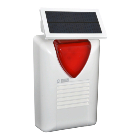
For connecting the autonomous siren type BS-413 up-to 7 cables are required.
On the terminals (+) και (-) connect the voltage (AS), (-) which charges the siren.
When we supply the (ST) with 12V the siren and the beacon are activated. onnect (ST) to the P1
contact of the panel which is programmed to provide 12V during an alarm and 0V during the idle state.
When the (SE) terminal is connected to (-) it prohibits the siren to operate. This cable is connected to
a (-) terminal of the panel during the installation procedure or any other time that the cover of the siren
must be removed (i.e. during a battery change). In normal operation the cable must be removed from
the (-) terminal of the panel.
When the (FL) terminal is supplied with 12V the beacon is activated. If it is connected to the terminal
P3 of the panel then the beacon will flash once for 2 seconds when the panel is armed and three times
(0.5 second duration) when the panel is disarmed.
The contacts (Τ1) and (Τ2) are the TAMPER contacts of the siren which are connected to a respective
zone on the panel which by default is zone 8 (TAMPER zone).
To connect an internal siren BS-441, two cables are required. onnect the (ES) and (-) of the panel to
the respective (+) and (-) of the siren.
Each panel can accept up-to 2 external autonomous and 1 internal siren.

19
Zone connections
onnecting the panel with radars (infrared movement detectors, PIR) or other devices which require
power. For the connection, 4 cables are required (6 if the TAMPER is connected). The 2 cables are
connected to the (12V) and (-) of the panel and provide power to the respective terminals of all the
detectors. The other 2 cables connect in series the contacts RELAY (N ) of all the detectors of the
zone and the resistors found on the terminals of the panel. The diagram above provides examples for
connecting 1 or 2 detectors on the zones.
For the connection of mag-
netic contacts or other de-
vices that do not require
power only 2 cables are re-
quired.
The diagram to the left
shows the connections with
one or two magnetic con-
tacts on the zones.

20
Connection of smoke and heat detectors
The connection of the fire detectors is possible only if the zone which are connected is programmed
as a «FIRE» zone. The normally closed contacts of the relay on the base (N , ) are connected in
series with the resistor of the zone of the panel.
The power to the base is done using (-) and the output Ρ2 which by default is programmed as «SUP-
PLY FIRE DETE TOR».
3.3. Programming through the keyboard
When a user tries to change a setting in the user menu or the technician menu he can view the current
value of the setting. The only menus that do not offer the preview of default values are menus « ALL
ON» on the PSTN and GSM, as well as the 2 menus «EVENTS NOTIFI ATION» of the AR (Alarm
Receiving enter) of the PSTN and the GSM.
When a value is entered (i.e. entry time), and after the last digit is entered, the value is stored auto-
matically without the need of pressing an additional key. If the user does not reach the last digit of the
value and " * " is pressed, then the value that is shown on the display is stored. There is always an
indication on the display that shows which digit is edited. This is shown with the symbol ‘^’ under the
current digit.
When the adjacent display is shown, the system is in the process of
an important process which cannot be stopped by using the keyboard.
When the process finishes, the display will show the main menu. If a
problem occurs during the process then a relative message will be
shown before the return to the main menu.
UPDATING DATA..
Other manuals for BS-468/A
1
Table of contents
Other olympia electronics Security System manuals

olympia electronics
olympia electronics BS-458 User manual

olympia electronics
olympia electronics BSR-5036/A User manual

olympia electronics
olympia electronics BS-489 User manual

olympia electronics
olympia electronics BS-413 User manual

olympia electronics
olympia electronics BS-468/A/WL User manual

olympia electronics
olympia electronics BS-471 User manual

olympia electronics
olympia electronics ΒSR-5032 User manual

olympia electronics
olympia electronics BS-3001 User manual

olympia electronics
olympia electronics BS-475/B User manual

olympia electronics
olympia electronics BS-468/A User manual