LAWO mc256 MKII User manual

Technical Manual
mc²56 MKII
Version: 5.10.2/1
Edition: 12 September 2017

Copyright
All rights reserved. Permission to reprint or electronically reproduce any document or graphic in whole or
in part for any reason is expressly prohibited, unless prior written consent is obtained from the Lawo AG.
All trademarks and registered trademarks belong to their respective owners. It cannot be guaranteed that
all product names, products, trademarks, requisitions, regulations, guidelines, specifications and norms
are free from trade mark rights of third parties.
All entries in this document have been thoroughly checked; however no guarantee for correctness can be
given. Lawo AG cannot be held responsible for any misleading or incorrect information provided throughout
this manual.
Lawo AG reserves the right to change specifications at any time without notice.
© Lawo AG, 2017

mc²56 MKII Technical ManualV5.10.2/14
Welcome
Welcome
Welcome to the mc²56 MKII Technical Manual.
About this Manual
This documentation covers the installation, configuration and service/maintenance of the mc²56 MKII. The
specification is valid for mc2Version 5.10.2.x.
For more on operation, please see the "mc²56 MKII Operators Manual". All Lawo manuals are available from the
Download-Center at www.lawo.com (after Login).
Look out for the following which indicate:
Notes - points of clarification.
Tips - useful tips and short cuts.
Warnings
Alert you when an action should always be observed.
Software Updates
Lawo employ an ongoing development programme and offer free-of-charge software updates for all mc2/Nova
products. Releases can be downloaded from the Lawo website (after Login).
Utility Software Applications
The mxGUI installer is free to download from the Lawo website (after Login). Once installed, you can launch all
utility software applications including:
·
mxGUI - for offline setup or remote operation of the console.
·
AdminHD - to edit the system configuration.
·
CFCard Creator - to create backup CF Cards for the control system and, in a console, the bay server(s).
·
mxUpdater - to update the software of the mc2/Nova control system, or backup and restore user data.
Lawo User Registration
For access to the Download-Center and to receive regular product updates, please register at:
www.lawo.com/user-registration.
Additional Information
The "mc2_documentation" contains mechanical drawings, data sheets and further information on all system
components. This resource is included with the current mc2_56 software release, available from the Download-
Center at www.lawo.com (after Login).
We also recommend that you carefully observe the release notes delivered with your system.
mc²56 MKII Technical Manual V5.10.2/1 5
Important SafetyInstructions
Important Safety Instructions
General Safety
Warning
Exposure to excessive sound pressure levels can lead to impaired hearing and cause damage to the ear.
Please read and observe ALL of the following notes:
·
Check all of the hardware devices for transport damage.
·
Any devices showing signs of mechanical damage or damage from the spillage of liquids MUST NOT
be connected to the mains supply or disconnected from the mains immediately by pulling out the
power lead.
·
All devices MUST be grounded. Grounding connectors are provided on all devices. In addition, all
low-voltage devices external to the system must also be grounded before operation.
·
For Scandinavian countries, ALWAYS use a grounded mains connection, to prevent the device from
being grounded through Ethernet or other signal connections.
·
Do NOT use the system at extreme temperatures - observe the temperature range and humidity
specified in the installation instructions.
·
Do NOT expose devices to liquids which may drip or splash.
·
Do NOT place objects filled with liquids, such as vases, upon a device.
·
Only service staff may replace batteries.
·
CAUTION: Danger of explosion if battery is incorrectly replaced - Replace only with the same or
equivalent type.
Servicing of components inside a device MUST only be carried out by qualified service personnel according
to the following guidelines:
·
Before removing parts of the casing, shields, etc. the device MUST be switched off and disconnected
from all mains.
·
Before opening a device, the power supply capacitor MUST be discharged with a suitable resistor.
·
Components that carry heavy electrical loads, such as power transistors and resistors, should NOT
be touched until cool to avoid burns.
Servicing unprotected powered devices may only be carried out by qualified service personnel at their own
risk. The following instructions MUST be observed:
·
NEVER touch bare wires or circuitry.
·
Use insulated tools ONLY.
·
DO NOT touch metal semi-conductor casings as they can bear high voltages.
Eye Safety
Warning
This equipment may use Class 1 Laser products which emit invisible laser radiation that may lead to eye
injury.
·
NEVER look directly into optical components or optical fibre cables.
·
Fit protection caps to close any unused optical components.
·
Connect all optical fibre cables BEFORE turning on the equipment.
mc²56 MKII Technical ManualV5.10.2/16
Important SafetyInstructions
Defective Parts/Modules
Warning
mc²56 MKII contains no user-serviceable parts. Therefore DO NOT open the devices other than to perform
the procedures described in this manual.
In the event of a hardware defect, please send the system component to your local service representative
together with a detailed description of the fault. We would like to remind you to please check carefully
whether the failure is caused by erroneous configuration, operation or connection before sending parts for
repair. Please contact our service department before sending parts for repair.
First Aid (in the case of electric shock)
Warning
DO NOT touch the person or his/her clothing before power is turned off, otherwise you risk sustaining an
electric shock yourself.
Separate the person as quickly as possible from the electric power source as follows:
·
Switch off the equipment.
·
Unplug or disconnect the mains cable.
·
Move the person away from the power source by using dry insulating material (such as wood or
plastic).
If the person is unconscious:
·
Check their pulse and reanimate if their respiration is poor.
·
Lay the body down and turn it to one side. Call for a doctor immediately.
Having sustained an electric shock, ALWAYS consult a doctor.
mc²56 MKII Technical Manual V5.10.2/1 7
Chapter 1: Technical Overview
Chapter 1: Technical Overview
This chapter introduces the technical components of the mc²56 MKII system:
·
Hardware Components
·
RAVENNA Interfaces
·
Redundancy
·
Sample Rate & System Clock
·
Networking I/O Resources
·
IP-SHARE Gain Compensation
·
Configuration
·
System Options

mc²56 MKII Technical ManualV5.10.2/18
Chapter 1: Technical Overview
Hardware Components
Hardware Components
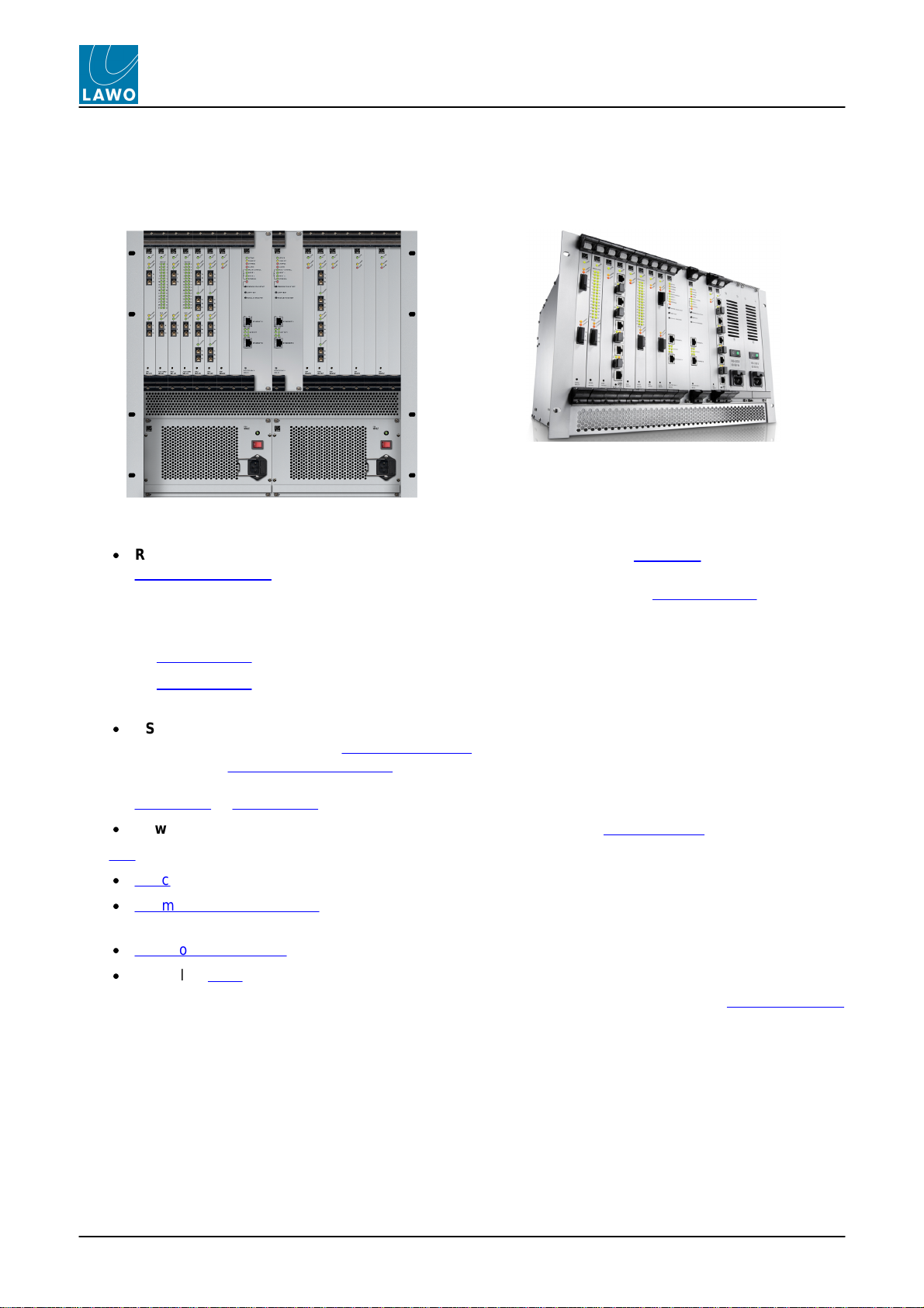
The mc²56 MKII consists of three principal components:
·
Console control surface - with integrated power supplies and local I/O connections.
·
Nova73 – with Router Modules, DSP boards and AES, MADI, RAVENNA or DANTE I/O. Available in two
sizes: Nova73 HD (10RU) or Nova73 Compact (7RU).
·
DALLIS or Compact I/O – offering further I/O breakout options. DALLIS frames can be fitted with a
choice of I/O cards and connect to the Nova73 via MADI or RAVENNA. The Compact I/O is a 5RU
stagebox with a fixed amount of I/O; it connects to the Nova73 via RAVENNA Link.
The exact hardware specification defines how many analogue and digital connections are available for external
equipment, and how much DSP processing is available for input channels, monitor return channels, groups, sums
and auxiliary sends.
From Version 5.4 onwards, two identical control surfaces can connect to the same Nova73 in order to mirror
each other - for example, in a theatre you can install one surface in the auditorium and the other in a
separate control room to facilitate mixing from two different locations. The surfaces MUST be from the same
console family (either mc256 OR mc266), but different frame sizes are possible. For more details, see
Installing a Mirror Desk.

mc²56 MKII Technical Manual V5.10.2/1 9
Chapter 1: Technical Overview
Hardware Components
Console Control Surface
The mc²56 MKII control surface is constructed in 16-fader sections, with frame sizes scaling from 16 faders up to
80 faders. you can add 16-fader extenders to expand the number of fader strips.
A range of console options offer wide (studio) or narrow (OB) side panels, table-top or stand mounting, overbridge
metering, etc.
Control surface power is provided by internal power supplies, with n+1 redundancy and two mains connections for
phase redundancy. PSU status can be monitored from the console GUI.
All application software and user data is handled by the control system, located on the Router Module MKII within
the Nova73. The surface connects to the Nova73 via TCP/IP Ethernet; if a redundant Router Module is fitted, then
main and backup connections can be installed.
The control surface also houses a local I/O board, for monitoring, metering, talkback and headphones. This is
available in two versions, connecting to the Nova73 via either MADI or RAVENNA.
As the control system is integrated within the Nova73, the control surface can be powered off without loss of
user data or audio!
mc²56 MKII Technical ManualV5.10.2/110
Chapter 1: Technical Overview
Hardware Components
Nova73
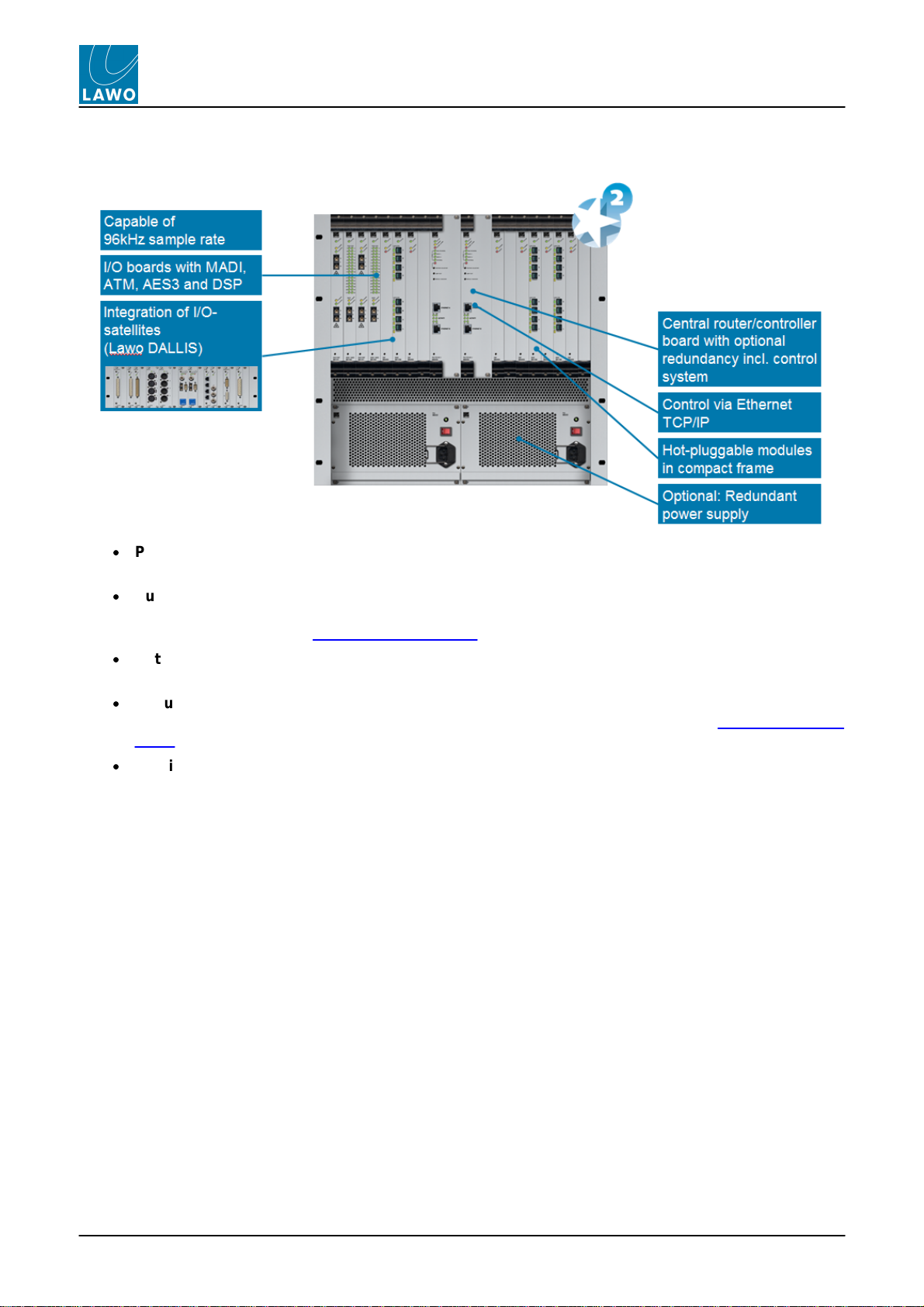
The Nova73 forms the "heart" of the system, and is available in two sizes - Nova73 HD (10RU) or Nova73
Compact (7RU):
Nova73 HD (10RU)
Nova73 Compact (7RU)
In each case, the front of the frame houses the:
·
Router Modules MKII - two central slots are available for a main and redundant Router Module. The
Router Module MKII (980/33) contains the summing matrix AND control system. The summing matrix
offers a 8k2capacity* router at 48kHz (or 4k2capacity at 96kHz). The control system runs on an
embedded Linux operating system, and stores both the application software and user data. Connections
are made via the two TCP/IP Ethernet ports:
oETHERNET A – connects to the control surface.
oETHERNET B – connects to the Lawo system network (to other Lawo devices; third-party controllers;
computers running configuration, maintenance or remote control software).
·
DSP and I/O Modules - 16* slots are available for plug-in DSP or I/O modules. Up to 8* DSP boards can
be fitted supporting a range of DSP configurations; I/O options include AES/EBU, MADI, RAVENNA and
DANTE, see Nova73 Module Options. All modules are hot-pluggable enabling them to be be replaced
without affecting other aspects of the system. Further breakout formats are realised by connecting to
DALLIS I/O or Compact I/O stageboxes.
·
Power Supply Units - two slots are available for main and redundant power supplies.
The rear of the frame houses the:
·
Sync ports - accepting Wordclock, AES/EBU (AES3-id) or Video Black Burst (PAL or NTSC).
·
Alarm and control contacts - including a global alarm; prepare cold start; force redundant Router Module
takeover.
·
AES connector panels - for front-mounted AES3 I/O modules.
·
5* Cooling Fans - hot-pluggable and easily accessible.
* The figures above are for the Nova73 HD. For more details on the Compact core, see the Nova73 Compact
Appendix.

mc²56 MKII Technical Manual V5.10.2/1 11
Chapter 1: Technical Overview
Hardware Components
DALLIS I/O
Front View
Rear View
The I/O capabilities of the system are expanded by adding DALLIS unit(s). Each can be either 3RU (shown
above) or 6RU in height, and may be remote from the rest of the system.
The front of the frame houses the:
·
DALLIS Master Boards - two central slots are provided for a main and redundant master board. A choice
of board types provide connection to/from the Nova via MADI or RAVENNA, see DALLIS Interface
Options.
The type of DALLIS master board, and hence the connection, determines the maximum number of audio
channels to/from the Nova: up to 60 (MADI) or 128 (RAVENNA).
·
DALLIS I/O cards - 18 slots are available for a range of I/O breakout options (Mic/Line, Line, AES, SDI,
GPIO, etc.), see DALLIS Interface Options.
All cards are hot plug-able, with the exception of Phantom Power.
The rear of the frame provides access to:
·
Main and redundant power supplies
·
Alarm and control contacts - including a local DALLIS alarm.

mc²56 MKII Technical ManualV5.10.2/112
Chapter 1: Technical Overview
Hardware Components
Compact I/O
Front View
As an alternative to DALLIS I/O, the Compact I/O is a 5RU stagebox with a fixed amount of I/O that connects to
the Nova via RAVENNA technology.
Each unit provides 32 mic/line in, 32 line out, 8 AES in, 8 AES out, 8 GPIO and 1 MADI port, and is fitted with
dual redundant power supplies. Each stagebox is delivered as a self-contained unit and comes with the required
RAVENNA network cable.
From Version 5.10.0 software onwards, the Compact I/O can connect via either RAVENNA Link or RAVENNA
Net - the type of connection is defined in the AdminHD configuration. Note that it is important to connect to the
correct port. Connections are made using standard CAT 5/6/7 Gigabit Ethernet, RJ45 connectors, crossed or
straight (1:1) cable, up to 80m. A network cable is delivered with the Compact I/O.
Using RAVENNALink
RAVENNA Link connections must be directly wired. Providing the correct RAVENNA port is connected (to match
the AdminHD configuration), the interface is self-configuring. Thus, once you have connected the ports (e.g. from
the Nova to Compact I/O), no further network configuration is necessary.
Warning
To guarantee low latency, reliability and easy setup, do NOT connect any other network equipment between
RAVENNA Link connections.
Using RAVENNANet
RAVENNA Net connections must be made via the streaming network (i.e. to the RAVENNA network switch). This
will ensure that the network's PTP clock signal (essential for RAVENNA streaming) is available to the streaming
port. In this instance, you must make sure that the correct RAVENNA role names are configured (within
AdminHD and each partnering device) and, in the case of any virtual devices, that the streaming IP address is
also defined. For full details, please refer to the "RAVENNA for mc2/Nova User Guide".
Warning
RAVENNA streaming requires proper configuration and management of the data network. The network must
use a suitable architecture; all components must support multicast (as opposed to unicast); a proper Quality
of Service (QoS) must be configured; and so on. Please DO NOT attempt to connect RAVENNA interfaces
using an unknown or unqualifying IP network. If you do so, correct streaming operation cannot be
guaranteed.
For more details, see RAVENNA Interfaces.
mc²56 MKII Technical Manual V5.10.2/1 13
Chapter 1: Technical Overview
Hardware Components
Local I/O
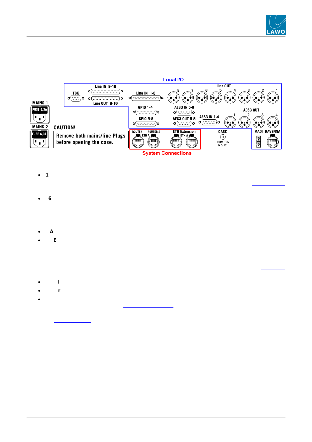
The mc256 MKII control surface includes an integrated local I/O board. This provides dedicated connections for
local devices such as monitoring, metering, talkback and headphones.
All local I/O connections are accessed from the control surface rear panel:
The local I/O provides:
·
16 Line In - wired to 2 x DSub (female).
Note that Line In 16 can be fed from the integrated talkback mic preamp, according to the jumper switch
positions set for the Local I/O.
·
16 Line Out:
oLine Out 1-8 - wired to 8 x XLR (male). By default, these outputs are routed from the CRM 1 monitor
output.
oLine Out 9-16 - wired to 1 x DSub (male).
·
8 AES3 In - wired to 2 x DSub (female).
·
8 AES3 Out:
oAES3 Out 1-4 - wired to 4 x XLR (male).
oAES3 Out 5-8 - wired to 1 x DSub (male).
Note that AES IN 5-8 and AES OUT 5-8 connect to the RTW meter, if either of the TM 7 or TM 9 Overbridge
options are fitted.
·
8 GPIO - wired to 2 x DSub.
·
2 Stereo Headphones - wired to the headphone 1 & 2 connectors on the console's front buffer.
·
1 MADI or 1 RAVENNA - the local I/O board is available in two versions, connecting to the Nova73 via
either MADI or RAVENNA (see Local I/O Connection). You will need to reserve one MADI, or one
RAVENNA, port within the Nova73 for this connection.
Please see Local I/O Wiring for more details on wiring, pin-outs and jumper switch options.

mc²56 MKII Technical ManualV5.10.2/114
Chapter 1: Technical Overview
RAVENNAInterfaces
RAVENNA Interfaces
RAVENNA is implemented throughout the Lawo product range. In mc2/Nova systems, it can be used to replace
MADI as the audio interconnect between the Nova routing matrix and DALLIS stageboxes. Or, to distribute
signals to other RAVENNA-compatible devices.
In this example two different types of RAVENNA are in use:
·
RAVENNA Net (IP Layer 3) - for connections to remote DALLIS and other RAVENNA-compatible devices.
·
RAVENNA Link 1.0 - a proprietary implementation of RAVENNA used for directly-wired connections (up
to 80m).
RAVENNA "Links" (Link 1.0) are recommended for local point-to-point connections such as those from the
console's Local IO and DALLIS units to the system Core (e.g. Nova73). This is because, once they are defined by
AdminHD, the Links are self-configuring and have no impact on the streaming network's bandwidth or
configuration. RAVENNA Links must be directly wired; connection via a network switch is not permitted.
RAVENNA "Net" (IP Layer 3) offers more flexibility as signals are distributed via the IP network. Each streaming
port can be configured as a DALLIS, Virtual Devices or Tie-line port supporting up to 128 bi-directional channels.
DALLIS ports may connect to a single 128-channel, or two 64-channel DALLIS frames, making RAVENNA more
flexible and port-efficient than its MADI equivalent. Virtual Device ports support up to 16 x 8-channel devices
including Lawo's A__line and LCU (Lawo Commentary Unit), and Neumann's DMI-8. RAVENNA Tie-Lines should
be configured to support streaming to/from other RAVENNA-compatible devices. Synchronization of the
RAVENNA streaming network requires a PTP master clock source. This can be achieved by using one of the
RAVENNA nodes as PTP master or by installing a third-party PTP Grandmaster device.
For more information on installing, connecting and configuring a RAVENNA network, please see the separate
"RAVENNA for mc2/Nova User Guide" and "RAVENNA Networking Guide".
mc²56 MKII Technical Manual V5.10.2/1 15
Chapter 1: Technical Overview
Redundancy
Redundancy
One of the strengths of the mc²56 MKII is its ability to withstand component failures, and every component is
designed with fault tolerance in mind:
·
Star2Technology
·
Link & Port Redundancy
·
Nova73 & DALLIS Power
·
Redundant DSP
·
Control System
·
Redundant Router Module and Control System
·
Control Surface Power
·
Control Surface Internal Wiring
mc²56 MKII Technical ManualV5.10.2/116
Chapter 1: Technical Overview
Redundancy
Star2 Technology
All components within the system utilise Lawo’s Star2technology:
·
Point-to-point connections – with point-to-point connections, a fault only affects that part of the system,
unlike a TDM bus architecture where a fault may disrupt everything connected to the bus!
·
Dual star topology – with redundant Router Modules fitted to the Nova73, and redundant Master Boards
in every DALLIS, then components connect in a dual ‘star’ mode. This protects signal paths from any
single point-of-failure. See Link & Port Redundancy.
·
Hot-swappable Modules/Cards – every plug-in module or card can be hot-swapped without affecting the
rest of the system enabling online maintenance of the system.
·
Redundant Power Supply Units – both Nova73 and DALLIS units can be fitted with dual redundant
power supplies, which can be isolated and exchanged from the front or rear. See Nova73 & DALLIS
power.
·
Passive backplanes – the frame backplanes are entirely passive. With no active components, this
increases reliability.

mc²56 MKII Technical Manual V5.10.2/1 17
Chapter 1: Technical Overview
Redundancy
Link & Port Redundancy
For crucial interconnections between say a DALLIS and mc2/Nova I/O Module, you can specify either link, or link
and port, redundancy:
·
Link Redundancy – two physical connections (MADI or RAVENNA) are made from the DALLIS master
board to the mc2/Nova module. If the active link fails, then the redundant link ensures an automatic
recovery.
·
Link & Port Redundancy - two master boards are fitted to each DALLIS, and connect to different
mc2/Nova ports (preferably on a different module). Port redundancy provides automatic recovery from a:
oFailure of the active physical link (MADI or RAVENNA).
oMalfunction of the active DALLIS master board.
oMalfunction of the mc2/Nova module.
To specify link redundancy:
·
MADI - order a double-port Nova73 module and DALLIS master board for each connection.
·
RAVENNA - install both the copper and fibre optic connections from the RAVENNA module / master
board.
To specify link & port redundancy:
·
MADI or RAVENNA - order two master boards per DALLIS plus enough single-port Nova I/O modules to
support the connections. AdminHD configures which ports provide redundancy.
mc²56 MKII Technical ManualV5.10.2/118
Chapter 1: Technical Overview
Redundancy
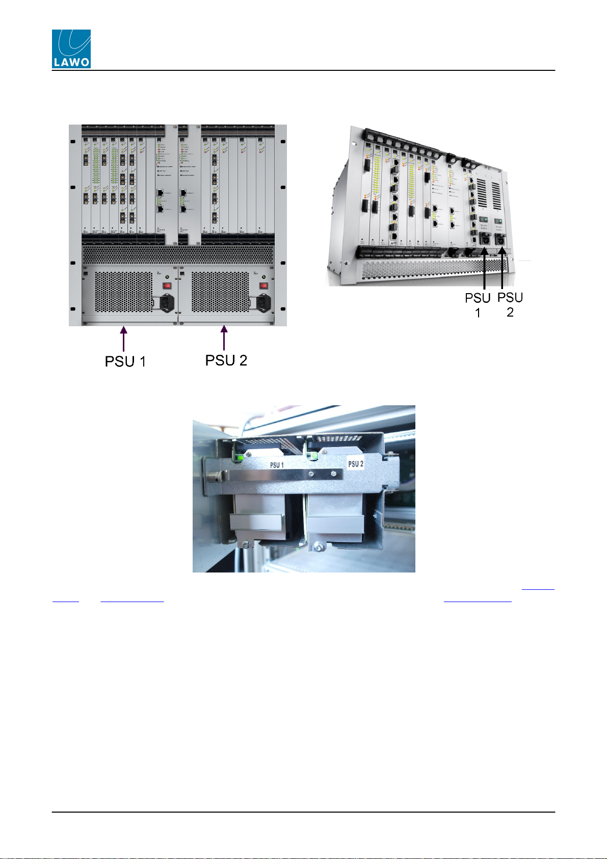
Nova73 & DALLIS Power
Nova73 HD front view
Nova73 Compact front view
DALLIS internal view of PSUs
The Nova73 HD, Nova73 Compact and DALLIS provide two slots for dual redundant power supplies, see Nova73
power and DALLIS power. Their status can be monitored from the console GUI using the Signal Settings display.

mc²56 MKII Technical Manual V5.10.2/1 19
Chapter 1: Technical Overview
Redundancy
Redundant DSP
Within the Nova73 a DSP board can be reserved to provide redundant processing (indicated by the STANDBY
LED).
In the unlikely event of a failure, the system automatically switches all DSP resources and settings from the faulty
board to the spare; the faulty board can then be safely removed and replaced.
This option is enabled from the console GUI using the DSP Configurations display, and is saved within the
production.
mc²56 MKII Technical ManualV5.10.2/120
Chapter 1: Technical Overview
Redundancy
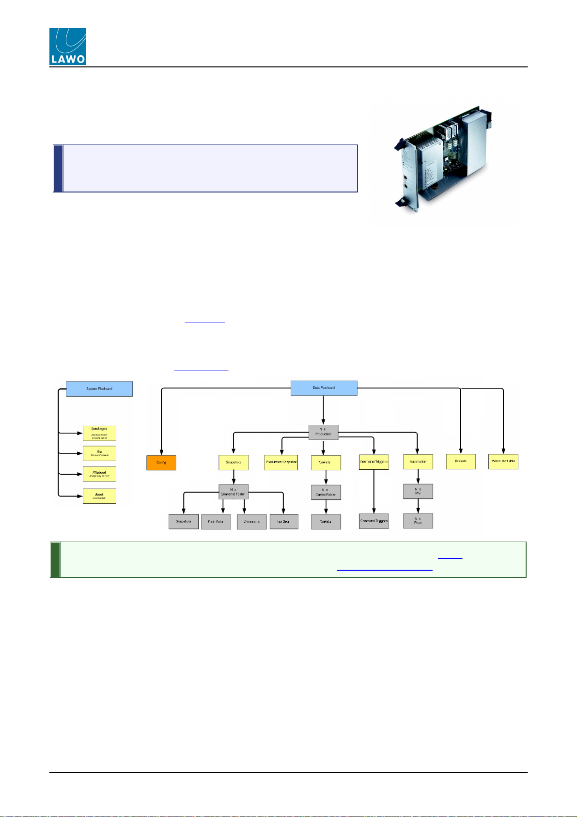
Control System
The control system resides on the Router Module MKII (980/33).
It runs on an embedded Linux operating system for speed and increased
reliability, and stores both the application software and user data.
The Router Module MKII (980/33) contains a backup power unit
which provides up to 3 seconds of backup power to deal with short
interruptions to mains (AC) power.
WarmStart & Cold Start
Following switch-off, power is provided to the control system for a further 18 seconds. During this time, all current
settings are saved to flash memory; this is known as the system's warm start data.
By default, the warm start data is loaded at the end of boot-up. This means that the console comes back exactly
as it was when you last shut down, ensuring fast recovery of all previous settings following a loss of power.
Alternatively, you can perform a cold start if you suspect a problem with the warm start data.
Data Recovery
Two flash cards are used to store the application software (System Flashcard) and user data (Data Flashcard)
separately. You can create a backup copy of the flashcards so that they can be replaced if necessary.
During operation, any errors generated by the control system are stored in the message logfile. This can be
copied to USB via the File display, or monitored remotely via the Web Browser Interface.
Table of contents
Other LAWO Recording Equipment manuals


