Fie dbus device
Operation Manua
EX250 Series for CC-Link
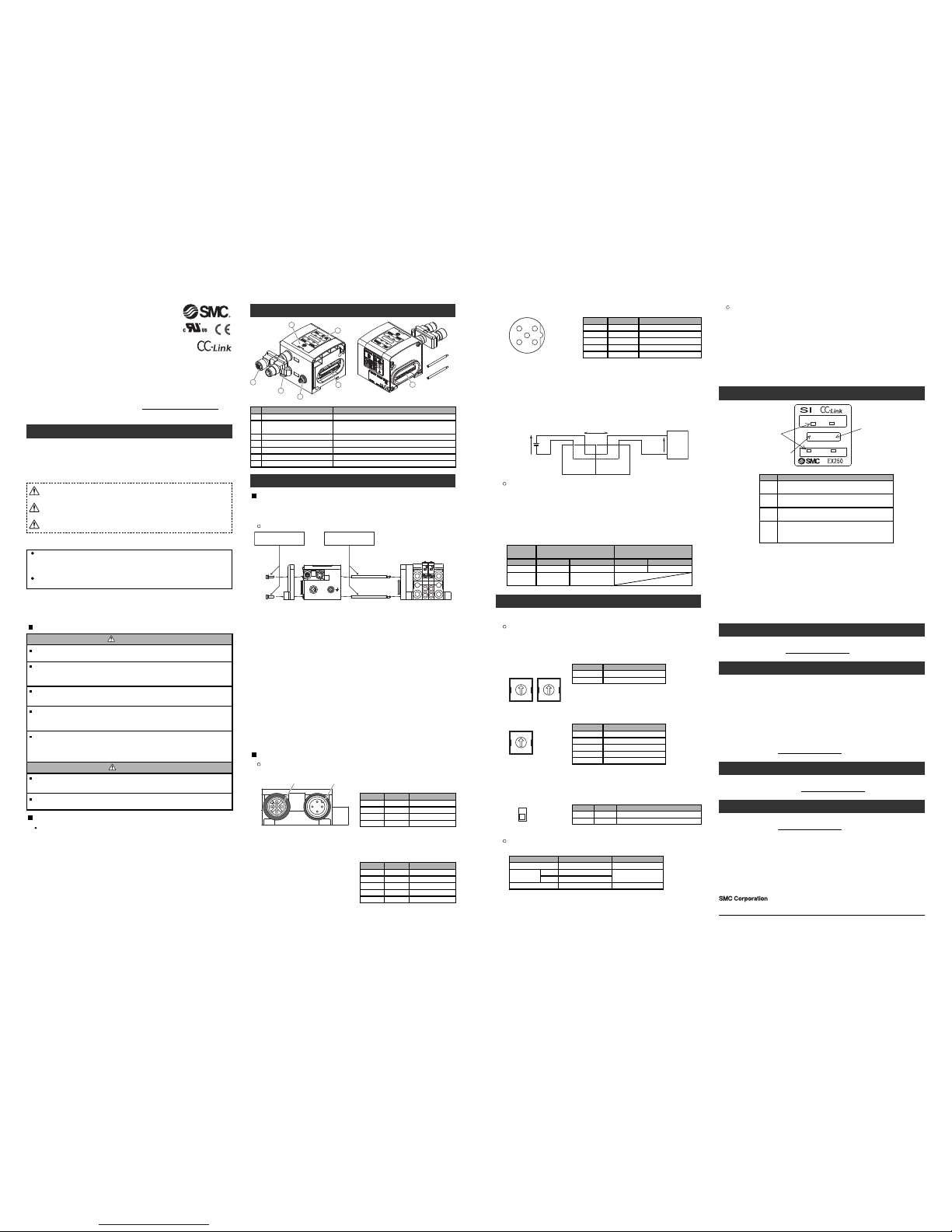
Summary of Product e ement
Mounting and Insta ation
Switch setting
Station No., Baud rate and HO D/C EAR are set by the switch inside of the SI unit
cover.
Set parameters while the power of SI unit is OFF.
The setting of each switches can be fixed after power is ON.
Communication connector
Description Function
Connect with CC- ink communication line. (Accessory)
Power supply connector Supplies power to the solenoid valve, the Output block, SI unit and
the Input block.
Input block connector Connects the Input block.
Display ED display shows the SI unit status.
Switch protective cover Set Station no. and Baud rate by using the switches under the cover.
1
No.
2
3
5
6
Ground terminal (FE) Used for grounding.
7
Output block connector
Connects the solenoid valve, Output block and etc.
4
Insta ation
Not having mounting hole, it can’t be set to BUS independently. Be sure to connect
manifold to SI unit for setting.
And if Input block is unnecessary, connect End plate directly to SI unit.
Setting
End plate SI unit
PWR
M3 hexagon screw
Tightening torque: 0.6 Nm
Tie rod
Tightening torque: 0.6 Nm
Valve manifold
RR
3
3
X
P
11
P
12 12
X
BB
AA
Exchange of SI unit
•Remove screws from End Plate and release connection of each unit.
•Replace old SI unit with new one. (Tie rod does not need to be removed.)
•Connect Input Block and End Plate and tighten removed screws by specified
tightening torque. (0.6 Nm)
Assembly and disconnection of unit
Addition of Input Block
•Remove screws from End Plate.
•Mount attached tie rod.
•Connect additional Input Block.
•Connect End Plate and tighten removed screws by specified tightening torque.
(0.6 Nm)
Caution for maintenance
(1) Be sure to turn-off all power supplies.
(2) Be sure that there is no foreign object in any of units.
(3) Be sure that gasket is lined properly.
(4) Be sure that tightening torque is according to specification.
If these items are not kept, it may lead to the breakage of substrate or intrusion of
liquid or dust into the units.
LED indication
LED
PWPW(V)
STATION NOB RATE
L RUN L ERR
×10 ×1
Rotary switch for
station no. setting
Rotary switch for baud
rate setting
ERR
ED Contents
ights up: Communication error.
Flashing: Assignment of station no. and baud rate are made
during communication. (Flicker every 0.4 s)
ights off: Communication is normal.
RUN ights up: Communication is normal.
ights off: Communication terminated. (Time over error)
PW
ights up: Input and control power is ON.
ights off: Input and control power is OFF.
PW (V) ights up: When power supply for solenoid valves is turned ON.
ights off: When supply voltage decreases below 19 V.
Troub eshooting
Technical documentation giving detailed troubleshooting information can be found
on the SMC website (UR http://www.smcworld.com).
Specifications
Out ine Dimensions
Technical documentation giving detailed outline dimensions information can be
found on the SMC website (UR http://www.smcworld.com).
Accessories
Technical documentation giving detailed accessories information can be found on
the SMC website (UR http://www.smcworld.com).
Assemb y and disconnection of unit
NOTE
When conformity to U is necessary the SI unit must be used with a U 1310
Class2 power supply.
Safety Instructions
Do not operate the product outside of the specifications.
Do not use for flammable or harmful fluids.
Fire, malfunction, or damage to the product can result.
Verify the specifications before use.
Do not disassemb e, modify (inc uding changing the printed circuit board) or repair.
An injury or failure can result.
Do not operate in an atmosphere containing f ammab e or exp osive gases.
Fire or an explosion can result.
This product is not designed to be explosion proof.
If using the product in an inter ocking circuit:
•Provide a double interlocking system, for example a mechanical system.
•Check the product regularly for proper operation.
Otherwise malfunction can result, causing an accident.
The fo owing instructions must be fo owed during maintenance:
•Turn off the power supply.
•Stop the air supply, exhaust the residual pressure and verify that the air is released before performing
maintenance.
Otherwise an injury can result.
Provide grounding to assure the safety and noise resistance of the Fie dbus system.
Individual grounding should be provided close to the product with a short cable.
Thank you for purchasing an SMC EX250 Series Fieldbus device (Hereinafter
referred to as "SI unit" ).
Please read this manual carefully before operating the product and make sure you
understand its capabilities and limitations.
Please keep this manual handy for future reference.
To obtain more detailed information about operating this product,
please refer to the SMC website (UR http://www.smcworld.com) or
contact SMC directly.
Safety Instructions
These safety instructions are intended to prevent hazardous situations and/or
equipment damage.
These instructions indicate the level of potential hazard with the labels of
"Caution", " Warning" or "Danger". They are all important notes for safety and
must be followed in addition to International standards (ISO/IEC) and other safety
regulations.
Warning
Caution
After maintenance is comp ete, perform appropriate functiona inspections.
Stop operation if the equipment does not function properly.
Safety cannot be assured in the case of unexpected malfunction.
CAUTION indicates a hazard with a low level of risk which, if
not avoided, could result in minor or moderate injury.
Caution:
Warning:
Danger:
WARNING indicates a hazard with a medium level of risk
which, if not avoided, could result in death or serious injury.
DANGER indicates a hazard with a high level of risk which, if
not avoided, will result in death or serious injury.
Operator
This operation manual is intended for those who have knowledge of machinery
using pneumatic equipment, and have sufficient knowledge of assembly,
operation and maintenace of such equipment. Only those persons are allowed
to perform assembly, operation and maintenance.
Read and understand this operation manual carefully before assembling,
operating or providing maintenance to the product.
Wiring
Communication wiring
•Communication connector (Bus adapter: EX9-ACY00-MJ)
INK IN: M12 4pins plug A-coded
LINK OUT LINK IN
1
2
3
4
1
2
3
4
5
S D
Description Function
Shield
DB Communication wire DB
DG Communication wire DG
1
Pin No.
2
3
DA Communication wire DA4
Voltage drop of max.1 V
23 VDC Sensor
㸩㸫Input block
SI unit
SW power
24 VDC
Assignment of I/O number
•Standard wiring
The outputs of the SI unit are assigned from the D side solenoid valve in the order
0,1,2...maximum of 31.
Refer to each solenoid valves catalogue for details.
The inputs of the Input block are assigned from the SI unit side Input block in the
order 0,1,2…maximum of 31.
•Semi‐standard wiring for valve output (Mixed wiring)
As semi-standard wiring, mixed wiring inside the manifold is available. The wiring
type is specified by description of single or double solenoid valve mounted on the
manifold .In order to specify the mixed wiring, completion of Manifold type solenoid
valve Specifications Sheet is required.
Note: Specifications are subject to change without prior notice and any obligation on the part of the manufacturer.
© 2011 SMC Corporation All Rights Reserved
Akihabara UDX 15F, 4-14-1, Sotokanda, Chiyoda-ku, Tokyo 101-0021, JAPAN
Phone: +81 3-5207-8249 Fax: +81 3-5298-5362
URL http://www.smcworld.com
Example of the cable with connector: PCA-1567720 (SMC)
Example of the connector: PCA-1557620 (SMC)
INK OUT: M12 5pins socket A-coded
S D
Description Function
Shield
DB Communication wire DB
DG Communication wire DG
1
Pin No.
2
3
DA Communication wire DA4
- Unused5
Example of the cable with connector: PCA-1567717 (SMC)
Example of the connector: PCA-1557617 (SMC)
SV24 V
Description Function
+24 V for solenoid valve.
SV0 V 0 V for solenoid valve
SW24 V +24 V for SI unit and Input Block
FEGround
1
Pin No.
2
3
5
SW0 V 0 V for SI unit and Input Block4
M12 5pins plug B-coded (reverse)
•Power supply connector
Example of the cable with connector: EX9-AC010-1 (1 m)
EX9-AC030-1 (3 m)
EX9-AC050-1 (5 m) etc. (SMC)
Power for sensor is supplied to sensor connected with Input block. Select sensor
concerning voltage drop up to maximum 1 V inside the unit at this moment.
If sensor requires 24 V, it is necessary to lower power supply voltage for sensor
slightly or secure power supply for sensor separately without going through SI unit so
that sensor input voltage can be 24 V with actual loading (allowable voltage of power
supply: 19.2 V to 28.8 V).
•Station no. setting
0
5
73
4
1
2
9
8
6
0
5
73
4
1
2
9
8
6
10 1
STATION No.
x10
Setting Setting range
0 to 6
x1 0 to 9
∗: Set stations within 01 to 63
" ERR" display lights if 00 and station 64 or larger is selected.
Turn off the power and select correct station.
∗: " ERR" display blinks if the switch is operated which the
power is ON.
•Baud rate setting
1
Setting Setting range
156 kbps
2 625 kbps
∗: Set stations within 01 to 63
" ERR" display lights if 00 and station 64 or larger is selected.
Turn off the power and select correct station.
∗: " ERR" display blinks if the switch is operated which the
power is ON.
3 2.5 Mbps
4 5 Mbps
5 10 Mbps
Terminator
Station No. and Baud rate are set by the rotary switch inside of the SI unit cover.
Set parameters while the power of SI unit is OFF.
The setting of each switches can be fixed after power is ON.
Model
Ver. 1.10-compatible CC- ink dedicated cable
CC- ink dedicated (110 Ω,1/2 W)
CC- ink dedicated high-performance cable
(130 Ω,1/2 W)
Manufacturer
Cable to use
Correns
PHOENIX
CONTACT
Terminating resistance and cable
VA-4DCC-110
Power for SI unit/Input Block: 24 VDC ±20%, 1.1 A or less
Inside of SI unit: 0.1 A or less
Input block: 1 A or less (Depending on number of connecting
sensors and specifications)
Power for solenoid valve: 24 VDC +10%/5%, 2 A or less
(Depending on number of solenoid valve station and
specifications)
Connection load: Solenoid valve with protection circuit for 24 VDC and 1.5 W or less surge
voltage. (made by SMC)
Operating ambient temp: 5 to 45 oC Storage ambient temp: -20 to 60 oC
Pollution degree: Pollution degree 3 (U 508)
Technical documentation giving detailed specification information can be found on
the SMC website (UR http://www.smcworld.com).
)(
If this SI unit is the terminal of CC- ink connection, connect the terminal resistor to
"OUT" side of the bus adapter. There are two types of terminal resistors depending on
the cable to use.
Refer to the following table and select an appropriate terminal resister.
Color of molded portion
Black
SAC-4P-M12MS
CC TR Black
Model
VA-4DCC-130
Color of molded portion
Grey
•HO D/C EAR setting
H (ON)
Setting Function
Hold the last state before communication error.
C (OFF) Clear all outputs.
HO D
Contents
C EAR
Adjusted when shipped
B RATE (Baud rate)
Set parameters Switch setting
0
STATION NO. 0x10
0
Contents
156 kbps
0
x1
Please refer to the table below for setting at the time of shipment from the factory.
HO D/C EAR C(OFF) C EAR
"PW", "PW(V)", " RUN" light while data link is normal.


