LCI 426514 User manual

Smart Jack™
OWNER'S MANUAL

Rev: 07.09.18 Page 2 CCD-0001564
Introduction
The Aftermarket Smart Jack™features a high-efficiency motor, a new streamlined plastic shroud, and a new
user interface. These features, along with the single power lead and the hitch height memory, give the end
user a perfect reason to replace the traditional tongue jack with a far superior product.
Safety Requirements
Warning, Caution and Danger symbols indicate that an installation procedure has a safety risk involved and
may cause death, serious injury or property damage if not performed safely and within the parameters set
forth in this manual. Always wear eye protection when performing this installation procedure. Other safety
equipment to consider would be hearing protection, gloves, and possibly a full face shield, depending on
the nature of the installation procedure.
Failure to act in accordance with the following may result in death, serious injury or property
damage.
Moving parts can pinch, crush or cut. Keep clear at all times.
Lifting the unit off of the ground so that the unit's wheels are not touching the ground will create an
unstable and unsafe condition. Severe property damage, serious injury or death could occur. Keep
people and pets clear of the unit and work area while operating the leveling system.
Preparation
Be sure to park the unit on solid, level ground. Clear all jack landing locations of debris and obstructions.
Locations should also be free of depressions. When parking the unit on extremely soft surfaces, utilize load
distribution pads under each jack. Make sure tires are chocked.
Table of Contents
Introduction 2
Safety Requirements 2
Preparation 2
Powered Operation 3
Setting Hitch Height Memory 3
Normal Operation 3
Return to Hitch Height Operation 3
Auto Retract Operation 3
Manual Operation 4
Unhitching From Tow Vehicle 4
Hitching to Tow Vehicle 4
Smart Jack OEM Kit 5
Smart Jack Aftermarket Kit 6
Smart Jack Components 7

Rev: 07.09.18 Page 3 CCD-0001564
Powered Operation
The hitch height MUST be set in the memory prior to normal operation of the Smart Jack™. If the hitch
height is not set in the memory, the Smart Jack™and trailer will not function as intended.
NOTE: The battery indicator light (Fig. 1C) flashes or oscillates to validate certain functions of the Smart
Jack™. The light also displays the remaining battery charge of the trailer.
Setting Hitch Height Memory
1. Press and hold the up arrow (Fig. 1A) and down arrow (Fig. 1B) at the same time for a minimum of five
seconds to store the vertical position of the Smart Jack™.
2. The battery indicator lights (Fig. 1C) will flash five times to show that the new position has been
successfully stored in memory.
Normal Operation
1. Press and hold the up arrow (Fig. 1A) to extend the Smart Jack™.
2. Press and hold the down arrow (Fig. 1B) to retract the Smart Jack™.
Return to Hitch Height Operation
1. Press and release the up arrow (Fig. 1A) and the down arrow (Fig. 1B) at the same time 3 times, holding
on the 3rd time for several seconds until the jack engages and the indicator light oscillates back and
forth.
2. The Smart Jack™will automatically extend or retract to the original hitch height position stored in the
memory.
NOTE: Visual indication that the jack is actuating to the hitch height is seen through the oscillation of the
battery indicator lights (Fig. 1C) (e.g., lights will illuminate left to right, and then right to left). Battery
indicator light oscillation will continue until the original hitch height is achieved.
3. To cancel an action, press either the up arrow or down arrow. The action in progress will stop.
Auto Retract Operation
NOTE: This function should only be operated once the tow vehicle has been reconnected and secured to
the trailer prior to travel.
1. Press and release the down arrow three times (Fig. 1B), holding on the 3rd time until the jack engages
and the battery indicator light oscillates back and forth.
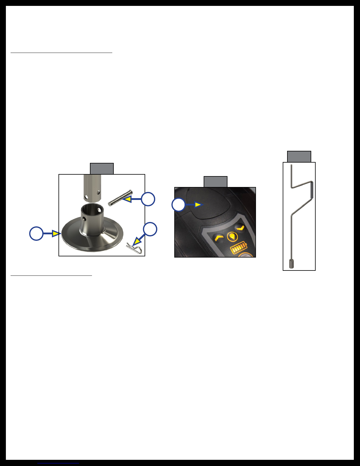
Fig. 1
A
B
C
Rev: 07.09.18 Page 4 CCD-0001564
Hitching to Tow Vehicle
1. Chock the tires of the trailer.
2. Be sure the footpad (Fig. 2A) of the Smart Jack™is pinned
securely in place with the Clevis Pin (Fig. 2B) and Hairpin Cotter Pin (Fig. 2C).
3. Remove the manual drive shaft plug (Fig. 3A) on top of the Smart Jack’s gearbox.
4. Insert the manual crank handle (Fig. 4) onto the manual drive shaft.
5. Turn the crank handle counterclockwise until the coupler properly mounts the hitch ball and the leg of
the Smart Jack™is fully retracted.
NOTE: The crank handle may need to be initially turned clockwise to extend the jack to clear the hitch ball
prior to retracting the jack.
6. Remove the crank handle (Fig. 4) from the drive shaft.
7. Reinsert the manual drive shaft plug (Fig. 3A).
NOTE: Make sure the leg of the Smart Jack
™
is fully retracted before moving the tow vehicle.
Manual Operation
If 12V DC power is unavailable to operate the Smart Jack
™
, use the following directions to manually operate the Smart
Jack
™
.
Unhitching From Tow Vehicle
1. Chock the tires of the trailer.
2. Be sure the footpad (Fig. 2A) of the Smart Jack™is pinned securely in place with the Clevis Pin (Fig. 2B)
and Hairpin Cotter Pin (Fig. 2C).
3. Make sure the ground surface under the Smart Jack™footpad is firm and level.
4. Remove the manual drive shaft plug (Fig. 3A) on top of the Smart Jack’s gearbox.
5. Insert the manual crank handle (Fig. 4) onto the manual drive shaft.
6. Turn the crank handle clockwise to extend the jack until the trailer is supported and the coupler clears
the tow vehicle's hitch ball.
7. Move the tow vehicle a safe distance away from the trailer.
8. Turn the crank handle either direction as needed until front of the trailer is level.
9. Remove the crank handle (Fig. 4) from the manual drive shaft.
10. Reinsert the manual drive shaft plug (Fig. 3A).
A
Fig. 2
B
C
Fig. 4
Fig. 3
A
Rev: 07.11.2018 Contact us: Lippert Components Inc. - www.lci1.com/support - Phone: (574) 537-8900 - Email: [email protected] Page 5 of 8
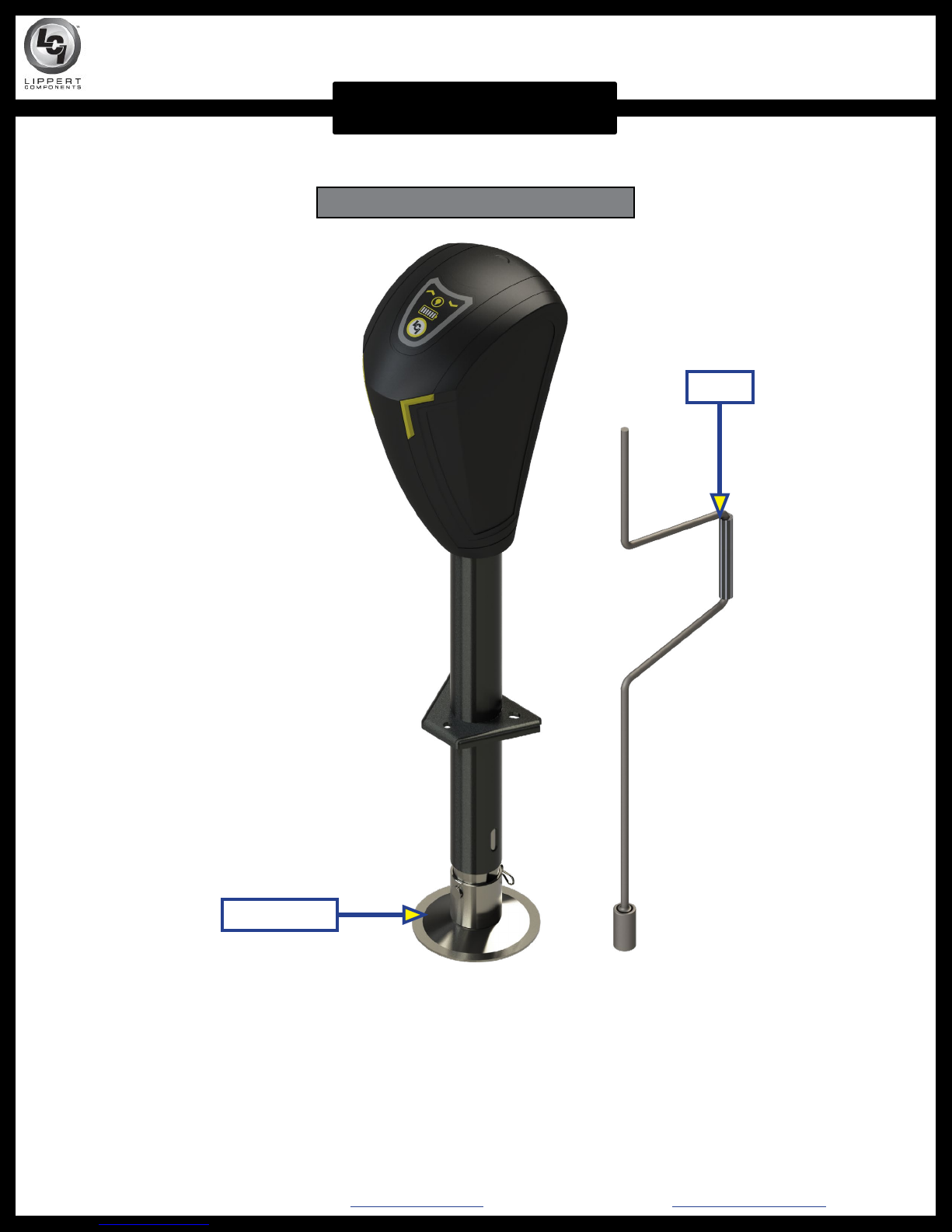
LEVELING AND STABILIZATION
SMART JACK™OEM ASSEMBLY
Smart Jack™OEM Kit - Part #426514
Crank
Footpad Kit

Rev: 07.11.2018 Contact us: Lippert Components Inc. - www.lci1.com/support - Phone: (574) 537-8900 - Email: [email protected] Page 6 of 8
LEVELING AND STABILIZATION
SMART JACK™AFTERMARKET ASSEMBLY
Footpad Kit
Crank
Smart Jack™Aftermarket Kit - Part #643589
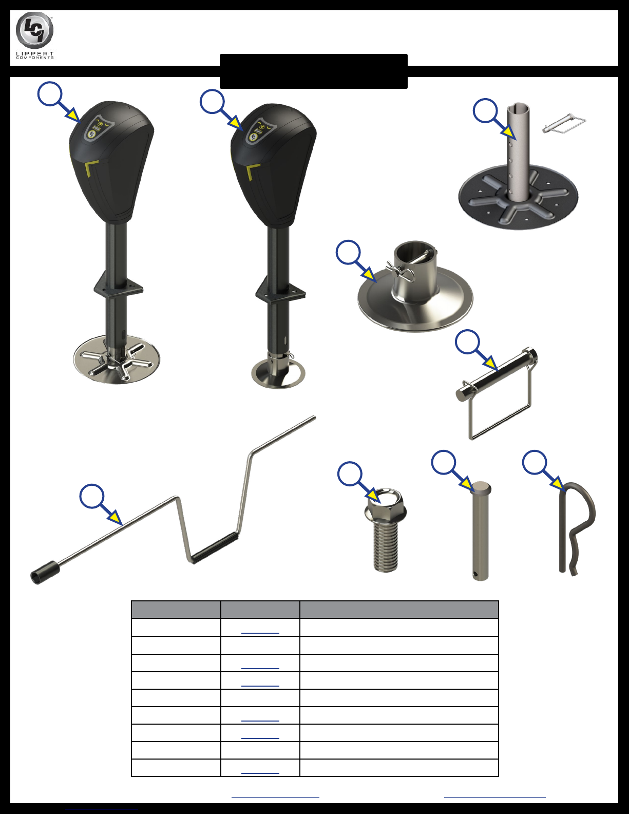
Rev: 07.11.2018 Contact us: Lippert Components Inc. - www.lci1.com/support - Phone: (574) 537-8900 - Email: [email protected] Page 7 of 8
LEVELING AND STABILIZATION
SMART JACK™COMPONENTS
F
E
D
AB
GH I
C
Callout Part # Description
A643589 Smart Jack™(Aftermarket Kit)
B 426514 Smart Jack™(OEM Kit)
C405217 Footpad (Aftermarket Kit)
D165253 Footpad (OEM Kit)
E 379674 Snapper Pin (Aftermarket Only)
F285324 Crank
G117919 Bolt
H 382844 Clevis Pin (OEM Only)
I178168 Hairpin Cotter Pin (OEM Only)

All information contained within may be distributed as a full document only, unless otherwise permitted by
explicit consent of Lippert Components Inc. to distribute individual parts.
All information contained within is subject to change without notice. New editions will be posted on www.
lci1.com and can be downloaded for free. Information contained within is considered factual until made
obsolete by a *NEW* revision.
Please recycle all obsolete materials.
For all concerns or questions, please contact
Lippert Components, Inc.
This manual suits for next models
1
Table of contents
Other LCI Accessories manuals


