Triton atmgurus ECDM-100 User manual

TDN 07103-43001 Rev A
©2023 Triton Systems of Delaware, LLC. All Rights Reserved. ATMGurus®, the ATMGurus logo and tag-
line, Triton®, and the Triton logo are all registered trademarks of Triton Systems of Delaware, LLC. e third
party trademarks that may be identi ed herein are the trademark of their respective owners. Triton disclaims any
affi liation, connection, or association between its products and services, and those of the respective trademark
owners, or any sponsorship or approval of its products and services by such trademark owners.
ECDM-100 Sensor Cleaning Guide

Triton Systems ©
2
TDN 07103-43001 Rev A
ECO 07103-43001
Revision Date Description
1033354 A 1/18/2023 Original: TDN 07103-43001 Rev. A assigned
C I
Triton©
21405 B Street
Long Beach, MS 39560 USA
1 (866) 787-4866 (opt 3) or +1 (228) 575-3100 (opt 3)
For detailed warranty information by unit, please visit www.triton.com.
is guide describes how to clean the ECDM-100 cash dispenser.
is manual applies to all service personnel involved in maintaining Triton ECDM-100 dispensers nationwide
and abroad.
is guide provides component locations that should be inspected and/or cleaned with air, alcohol, or swab.

Triton Systems ©
3
TDN 07103-43001 Rev A
Materials Required
#1 Phillips screwdriver
Recommend Electric Duster Model ED500 or equivalent
model. WARNING: DO NOT use Can of Air
Small Flashlight if available
70% ISO Prop Alcohol
Textured Absorbent Workshop Cloth, similar to image
Long Cotton Tip Package
OVERVIEW
Cash money circulates far and wide and changes hands throughout its lifespan. Notes pick up a lot of dirt and
grime during circulation. e ECDM-100 has (20) sensors, (68) rollers, and moving parts which contact notes
during a dispense operation. is manual will identify each of these sensors and parts and will describe methods
to keep the ECDM-100 clean and functioning normally. Take time to read this manual and familiarize yourself
with all the steps before starting the cleaning process.
SAFETY INFORMATION
Referenced from the Unit Front, the
manual transport Blue Drive Wheel
is located on the right side of the
unit.
ECDM C

Triton Systems ©
4
TDN 07103-43001 Rev A
1. Shut down the ATM and disconnect power.
2. Open the front cabinet vault door.
3. Slide the dispenser mechanism out as far as it will go. Disconnect the power and communications cables.
4. Locate the tray screws near the bottom-front of the dispenser, RED circles, Le Image. Use the Phillip
screwdriver to remove the screws. Save the screws to attach the ECDM to the tray later in the this document.
5. Use the Electric Duster or other means to blow dust and note particles out of the dispenser, Right Image.
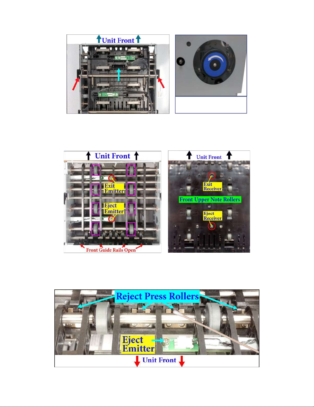
6. On top of the Upper Guide Doors, locate the sixteen (16) rollers, (8) MAGENTA rectangles and (8)
YELLOW circles. Dab a small section of the cloth in alcohol and hold it against each roller as the user turns
the Blue Drive Wheel in same direction of the wheel’s arrow.
7. YELLOW numbers identify the upper sensor receiver circuit boards.
• #1 = Exit Sensor
• #2 = Eject Sensor
• #3 = Right Diverter Sensor
• #4 = Le Diverter sensor
8. Locate the latch points for the (Front) Upper Guide door, two RED arrows. Pull/Push latch bar in direction
Triton Systems ©
5
TDN 07103-43001 Rev A
of the BLUE arrow, then li front Upper Guide Door to open.
9. Use the Electric Duster to blow the dust out of the dispenser.
Blue Drive Wheel on right
side when facing cassettes
10. Under the Upper Guide Door locate the eight (8) Note Feeding rollers, MAGENTA rectangles, Le Image.
Dab a small section of the cloth in alcohol and hold it against each roller as user turns the Blue Drive Wheel.
11. Dab a cotton tip in alcohol and swab the LEDs, RED circles, for the Exit/Eject Emitters, Le Image. Swab the
LEDs for the Eject/Exit Receivers, Right Image.
12. Locate four (4) Reject Press Rollers near the hinge point of the Front Upper Guide Door. Dab a cotton tip in
alcohol and hold against each Reject Press Roller.
13. Turn the Blue Drive Wheel in the OPPOSITE direction of the drive wheel arrow (Clockwise). is action
will turn the Reject Press Rollers. Turning the Drive Wheel in direction of arrow will NOT turn the rollers.

Triton Systems ©
6
TDN 07103-43001 Rev A
14. Close the front Upper Guide by Pulling/Pushing latch bar and press down. e bar should snap under the
catch on both sides. Should look like the label.
15. Locate the latch points for the (Rear) Upper Guide door, two RED arrows. Pull/Push latch bar in direction of
the BLUE arrow, then li rear Upper Guide Path to open.
16. Use the Electric Duster or other means to blow dust out of the dispenser.
Blue Drive Wheel on right
side when facing cassettes
17. Under the Rear Upper Guide locate the eight (8) Note Feeding Rollers, MAGENTA rectangles, Le Image.
Dab a small section of the cloth in alcohol and hold it against each roller as user turns the Blue Drive Wheel.
18. Dab a cotton tip in alcohol and swab the LEDs for the L/R Diverter Receivers and L/R Diverter Emitters,
RED circles, Right Image.
Triton Systems ©
7
TDN 07103-43001 Rev A
19. Close the Rear Upper Guide by Pulling/Pushing latch bar and press down. e bar should snap under the
catch on both sides. Should look like the label.
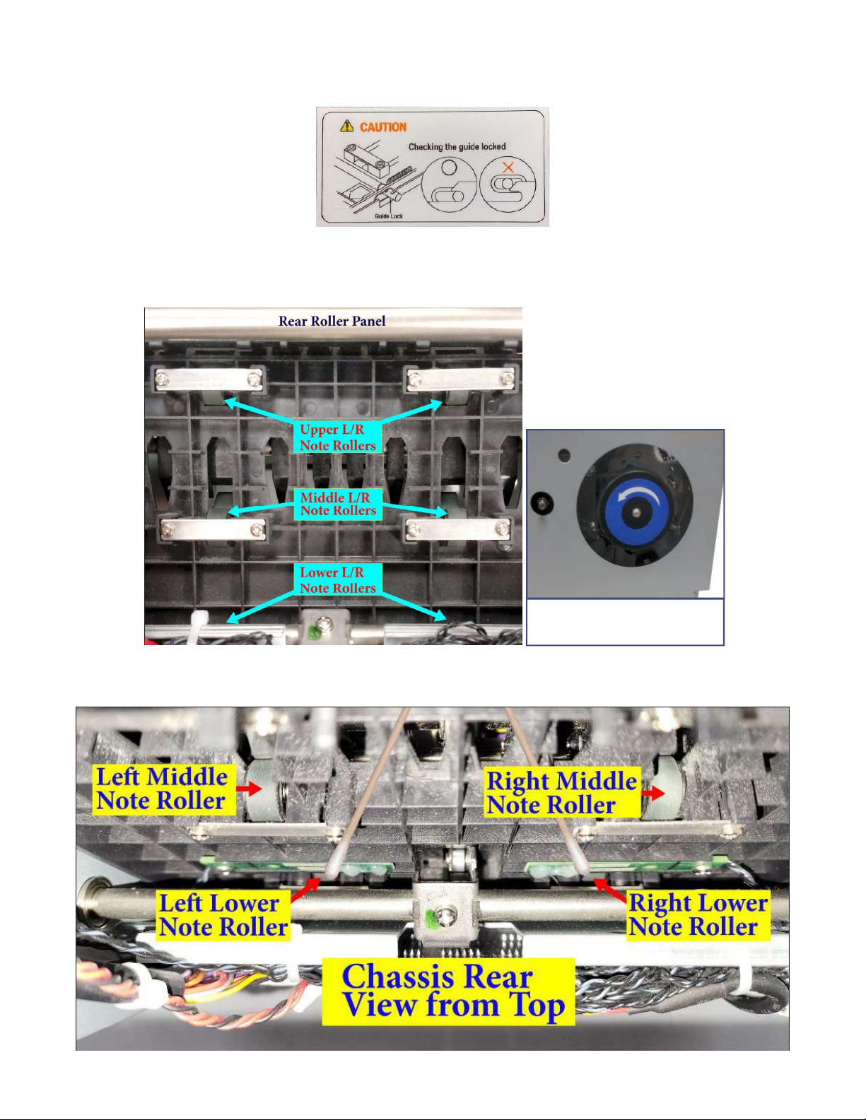
20. Use the Electric Duster to blow the dust out of the dispenser’s Rear Roller Panel, Le Image.
21. For the Upper and Middle L/R Note Rollers, dab a small section of the cloth in alcohol and hold it against
each roller as user turns the Blue Drive Wheel on side of unit.
Blue Drive Wheel on right
side when facing cassettes
22. Dab a cotton tip in alcohol and hold against Le and Right Lower Rollers, Image below, user turns the Blue
Drive Wheel.

Triton Systems ©
8
TDN 07103-43001 Rev A
23. Verify the front and rear Upper Guides are latched properly.
24. Carefully, turn dispenser on to its top with the circuit board facing the user.
25. Dab a cotton tip in alcohol and swab the LEDs for the L/R Check Emitters, Yellow arrows, Center Image.
26. Locate the hole below the Check Emitters, RED circles. Dab a cotton tip in alcohol, insert the cotton tip into
the hole to swab the LEDs for the Le Check Receivers, Le Images, and Right Check Receivers, Right Image.
27. Turn the dispenser back over. e smaller reject opening is above the cassette opening.
I R
(Viewed through cassette channel to rear of unit)
Internal Roller/Sensor Table
1. Upper Le Note Feeding Roller 11. Le Note Guide roller
2. Upper Right Note Feeding Roller 12. Right Note Guide roller
3. Middle Le Note Feeding Roller 13. Double Detect Roller and Clean Plate
4. Middle Right Note Feeding Roller 14. ECDM plug to Cassette
5. Lower Le Note Feeding Roller 15. Right Near-End Emitter Sensor
6. Lower Right Note Feeding Roller 16. Roller Guide
7. Le Note Feeding Roller 17. Le Near-End Receiver Sensor
8. Right Note Feeding Roller
9. Cassette Le Pickup Feeding Roller
10. Cassette Right Pickup Feeding Roller

Triton Systems ©
9
TDN 07103-43001 Rev A
28. Le Image, dab a small section of the cloth in alcohol and hold it against each Note Feeding Rollers (1,2,3,4)
as user turns the Blue Drive Wheel.
29. Le Image, the roller guide, Magenta rectangle, spins freely. Dab a cotton tip in alcohol and wipe the roller
side to side in parallel with roller bar, Yellow arrows. Turn roller quarter rotation and repeat wiping motion.
Viewed through
cassette channel
to rear of unit.
Blue Drive Wheel on right
side when facing cassettes
30. Center Image below, dab a small section of the cloth or cotton tip in alcohol. Hold cloth or cotton tip against
Note Feeding Rollers (5,6,7,8,9,10) as user turns the Blue Drive Wheel.
31. Right Image below, dab a cotton tip in alcohol. Move it back and forth, Yellow Arrows, against the Double
Detect roller as user turns the Blue Drive Wheel. DO NOT not let the cotton tip get caught between the
roller and cleaning plate. Reverse Drive Wheel’s direction to remove any cotton bers caught on the Double
Detect Roller.
Viewed through
cassette channel
to rear of unit.
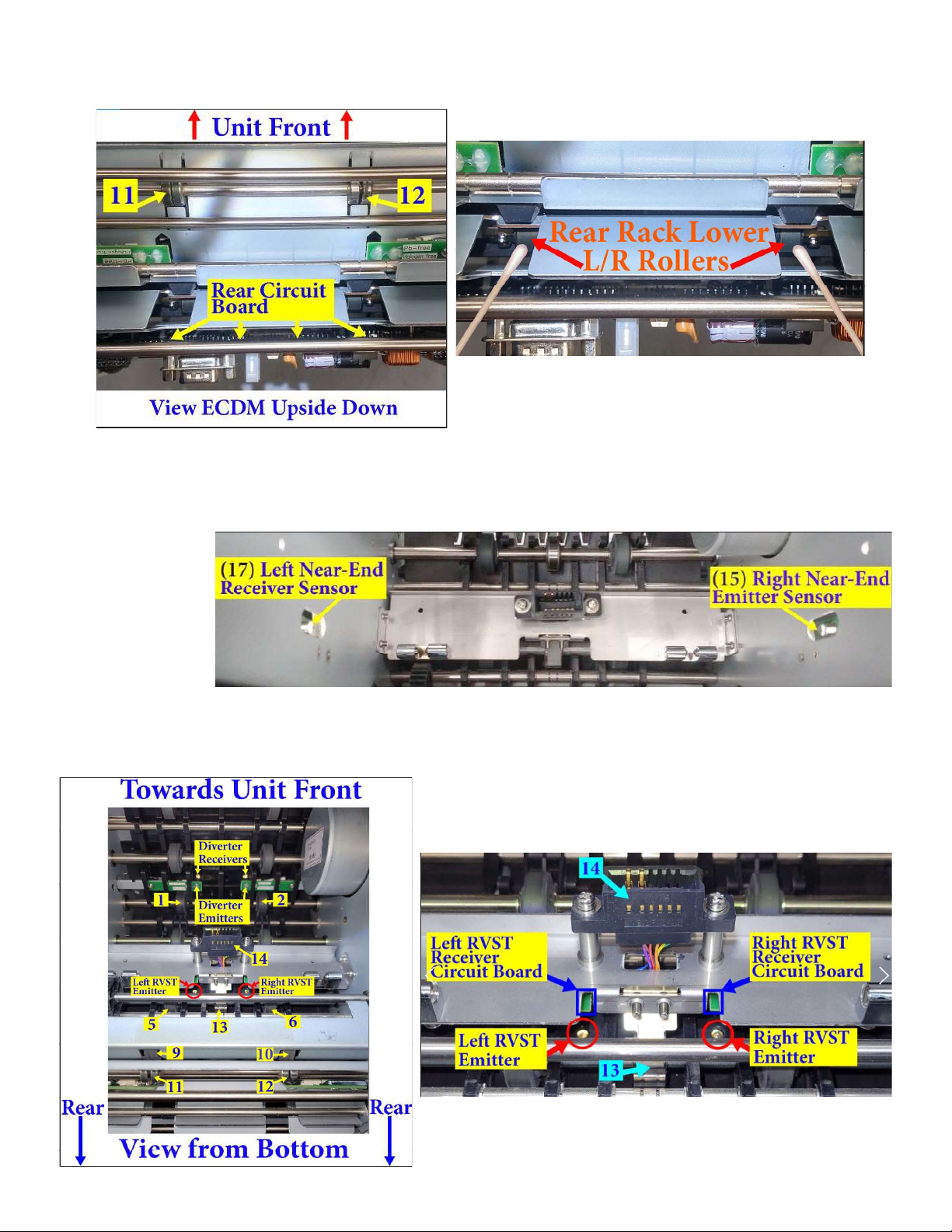
32. Dab a small section of the cloth in alcohol and hold it against each Note Rollers (11,12) as user turns the
Blue Drive Wheel. NOTE: Note Rollers in image show the lack of a proper cleaning.
Triton Systems ©
10
TDN 07103-43001 Rev A
33. Dab a cotton tip in alcohol and hold it against each Rear Rack Lower L/R Rollers as user turns the Blue Drive
Wheel. A er cleaning rollers, turn unit right-side up.
I S
34. Viewed through note cassette channel to rear of unit. Dab a cotton tip in alcohol and swab the LEDs for the
Le /Right Near-End Sensors.
Viewed through
cassette channel
to rear of unit.
35. Turn Unit upside down as shown for the two images below. Use a ash light to shine the Emitter lens. e
numbers are for reference to locate the RVST emitters, Le Image.
36. Dab a cotton tip in alcohol and swab the LEDs for the Le /Right RVST Emitters, Right Image, RED Circles.
Table of contents


