LDC EQUIPMENT LDC ABC Quick guide

Arrow Board Operators Manual V1.2 Page 1 of 12
LDC EQUIPMENT
LDC AB-C Size Arrow Board
Installation and Instruction Manual
Single Sided Arrow Board Controller
Quality Management System Approved to
AS/NZS ISO 9001:2008 –Reg. C31071
N21990

Arrow Board Operators Manual V1.2 Page 2 of 12
Thank you for purchasing an LDC Equipment
Arrow Board and AC4S Arrow Board Controller.
Proudly manufactured to conform to Australian Standard AS4192-2006.
Contents
Contents.................................................................................................................................................. 2
Introduction ............................................................................................................................................3
LDC AB-C Arrow Board............................................................................................................................4
Sign Positioning................................................................................................................................... 5
Inside the Control Box ........................................................................................................................5
Arrow Board Operation ..........................................................................................................................6
Operation............................................................................................................................................ 6
Controller Operation Modes for Arrow Board ................................................................................... 7
Fail-Safe Techniques Employed: ............................................................................................................. 7
Troubleshooting...................................................................................................................................... 8
Troubleshooting Guide ........................................................................................................................... 9
Safety ....................................................................................................................................................10
Maintenance .........................................................................................................................................10
Warranty ...............................................................................................................................................11
Disclaimer..............................................................................................................................................11
Spare Parts Listing.................................................................................................................................11
Specifications: C-Size Arrow board with Lift Motor............................................................................ 12
Specifications for AC4S Controller ........................................................................................................12
Document Revision History: ................................................................................................................. 12

Arrow Board Operators Manual V1.2 Page 3 of 12
Introduction
This fourth generation AC4S controller provides advanced functions, is easy to operate and
features a Colour OLED Screen to show the user the current operation and any diagnostic
information in the event of a failure or low battery situation.
The controls are designed for operation to AS4192-2006.
The controller includes a circuit breaker or isolator that provides for disconnection of power
in the event that service is required or in the event of an overload.
The controller screen displays the current operation mode and a real time mimic of the
Arrow Board lamps, as well as the operation of the Beacons (if fitted).
In addition the screen shows the current incoming Battery Voltage in the bottom left corner
and the current Sign Lamp Brightness in the bottom right corner.
When all operations are turned off the unit enters a low power state until the switches are
operated. The screen brightness is automatically adjusted to suit ambient light conditions.

Arrow Board Operators Manual V1.2 Page 4 of 12
LDC AB-C Arrow Board
AC4S Controller (Single and Double sided Arrow Boards)
Isolator switch
Optional Beacon Switch
OLED Display Screen
Control Knob
LED Lamps with Visors
Light Sensor
Solar Panel
Hydraulic Mast
Control Box

Arrow Board Operators Manual V1.2 Page 5 of 12
Sign Positioning
The sign must be positioned on reasonably flat, stable ground in a safe position clear of
obstructions, traffic and pedestrians.
Before removing the trailer from the tow hitch of the tow vehicle, the stabilising legs of
the trailer should be deployed to prevent the possibility of the trailer rolling once
unhitched.
Deploy the stabilising legs from their travelling position (horizontal) to their set up
position (vertical) by pulling out the spring loaded leg locking pin, and pivoting the leg 90
degrees until the locking pin re-locks the leg in position.
Wind the leg down until a firm footing is made with the ground.
Note! - All 4 legs MUST be deployed BEFORE raising the mast!
Inside the Control Box
Note: Solar panels should be cleaned weekly (more often depending on environmental factors).
Solar Regulator
Sealed Battery
AC4S Controller
ON / OFF
Raise/Lower
Mast
Toggle Switch
Hydraulic Mast
Pump

Arrow Board Operators Manual V1.2 Page 6 of 12
Single Sided Arrow Board Controller –AC4S
Arrow Board Operation
Operation
Once correctly set up with all 4 stabilising legs deployed, open the control box and raise the Arrow
Board high enough so it is clear of the trailer stirrups.
Rotate the sign to the desired position for viewing using the rotation locking lever.
Raise the sign to the required height using the mast raise/lower toggle switch.
To operate the controller, ensure that the Isolator switch is in the ‘On’ position. (There is no need to
operate the Isolator except when servicing the unit; the isolator switch should be left in the ON
position under normal circumstances.)
The sign is operated by turning the control knob so that the pointer points to the desired mode to be
displayed on the sign.
The mode selected on the controller, will be illuminated on the sign (as viewed from the REAR of the
vehicle).
When switched from OFF to an operation mode, the sign will automatically rise to its working
position, and the LED indicator on the control panel will light to show that the unit is in operation.
Note: The arrow board will fully rise before the sign begins flashing the selected display.
When switched OFF, after 2 seconds of inactivity, the sign will automatically lower to its travelling
position, and the LED indicator on the control panel will go out to show that the unit is off.
If the optional LED Beacons are fitted; the Beacons are controlled by the Beacons switch on the
controller. The Beacons will be shut off under low battery conditions. Pushing the toggle to the right
turns the Beacons on and to the left will turn them off.

Arrow Board Operators Manual V1.2 Page 7 of 12
Controller Operation Modes for Arrow Board
The sequence for the control knob/s is as follows:
OFF
REAR
OFF
NON DIRECTIONAL
WARNING
DOUBLEARROW
RIGHTARROW
LEFTARROW
Controller Operation Mode
ARROW BOARD DISPLAY
OFF
All lamps are OFF
LEFT ARROW
Lamps will display left arrow
RIGHT ARROW
Lamps will display right arrow
DOUBLE ARROW
Lamps will display double ended arrow
NON DIRECTIONAL WARNING (WIG WAG)
Lamps will alternate between top and bottom on
opposite sides.
Fail-Safe Techniques Employed:
Only 1 operation mode can be selected at once via the control knob. It is impossible to select
different flashing modes simultaneously. The flashing lamps of the Arrow Board is mimicked
on the controller display so the operator can see in real time what the sign is displaying.
During the normal operation of the system the AC4S controller communicates continually
with the Arrow Board computer, requesting the current status of the Arrow Board. Should a
non-corrected miscommunication be encountered, this will signal a fault to the AC4S display
to the operator.
The Arrow Board computer has a watchdog timer that will shut down all the lamps should
communication be interrupted, such as a disconnected or severed wire, or a catastrophic
failure of the system. This prevents any possible error of display of an incorrect symbol to
road users.
The Arrow Board computer has an operational voltage range of between 6 and 30 volts
without incorrect operation, and a watchdog timer will reset the computer in the event of a
software malfunction.
The AC4S controller likewise has a watchdog timer and an operational range of between 6
and 30 volts, thus the unit will provide normal function and failsafe operation over an
extended voltage range.

Arrow Board Operators Manual V1.2 Page 8 of 12
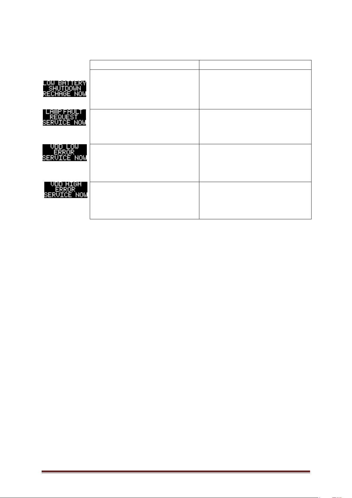
At a voltage drop of 11 volts or less, the system will enter the non-directional warning state
(mode D) indicated on both the sign and the AC4S controller.
At a further voltage drop to 10.4 volts the lamp modules will cease to illuminate completely.
(System enters low voltage shut down) until power is restored to 11.6 volts or above, when
the sign will again turn on and resume normal function.
The current used by the Arrow Board lamps is constantly monitored by a microcontroller on
the Arrow Board computer, if the current is detected to be outside the range of normal
operation, an error is generated and the user is informed on the AC4S controller and the
Arrow Board is shut down.
Troubleshooting
The AC4S Arrow Controller and Arrow Board are similar in operation to a computer network. The
control switches on the Arrow Controller are the master controls and communicate with the
computer in the Arrow board, which in turn responds to given commands. The unit also has a light
sensor mounted at the bottom of the Arrow Board
If the LED display on the controller does not light, check the isolator switch to ensure it is in the
ON or RESET position.
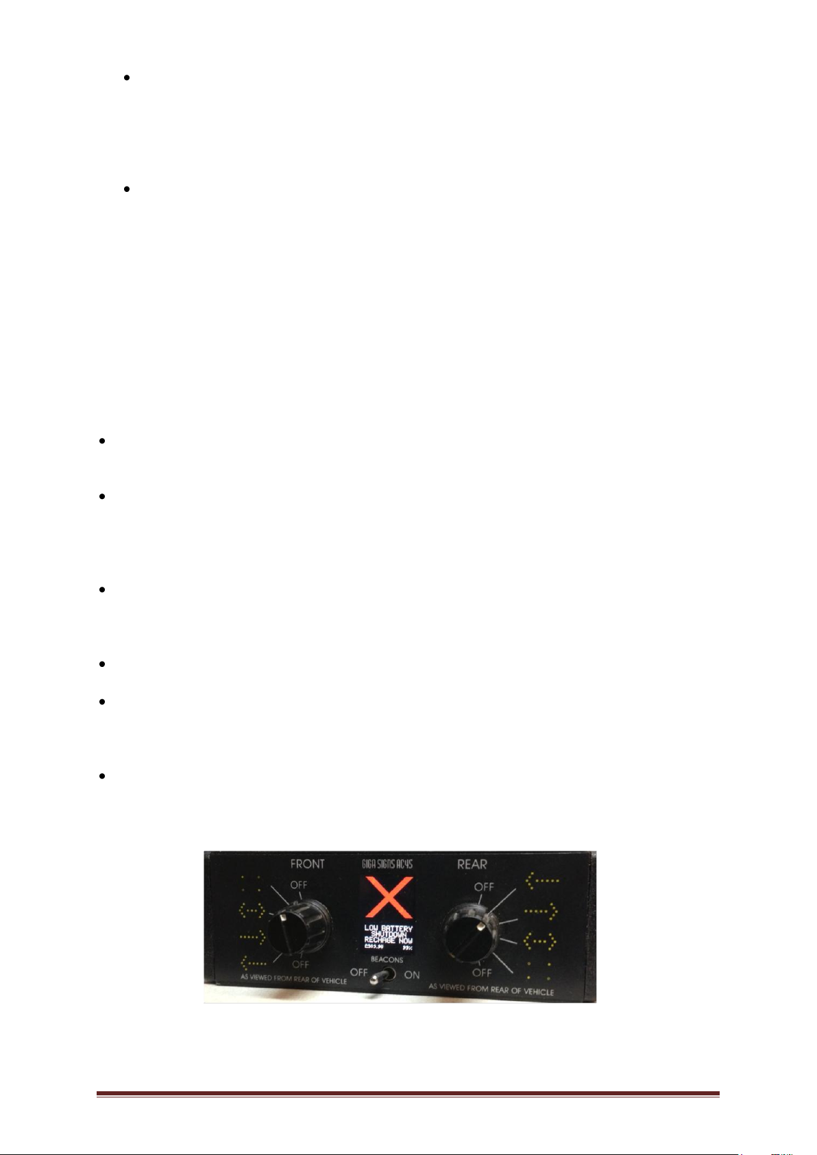
In the event of a failure of any kind, the sign will enter an error state as indicated by a large red X
on the controller screen and the sign will stop operating.
Note: No change of mode will take place to the flashing of the sign, it will stop.
If the unit fails to operate, first check that the Isolator is switched ON (RESET), this isolator is also
a circuit breaker and will automatically switch off, should the wiring to the Arrow Board be
damaged, or there is a failure in one of the Arrow Board modules.
To reset the system, switch the isolator to OFF, wait 10 seconds and turn ON (RESET).
The system automatically dims the lamps in response to a light sensor mounted at the bottom of
the Arrow Board, if the lamps appear dull during daylight hours; clean the light sensor with a
damp cloth.
In the case where one or more of the lamp units fail to light as normal, or if any of the lamps
appear as unusually bright or dim, first check the lamp units are clean and that the apparent
difference is not due to dirt on the LEDs or an obstruction in the shroud.

Arrow Board Operators Manual V1.2 Page 9 of 12
Troubleshooting Guide
Possible errors the user may encounter:
Error Description:
Action:
“Low Battery Voltage”
The battery is low and the unit has
shut down due to insufficient power
Recharge the battery or check the
wiring from the battery to the
controller for poor connections.
Replace the battery if necessary.
“Lamp Fault”
One or more lamps have failed.
Visually check operation of lamps,
check lamp connections, repair wiring
or replace any that have failed.
“VDD Low”
Indicates a non-user serviceable error
with the AC4S controller.
Return for repair or exchange.
“VDD High”
Indicates a non-user serviceable error
with the AC4S controller.
Return for repair or exchange.

Arrow Board Operators Manual V1.2 Page 10 of 12
Safety
ALL ELECTRICAL WORK SHOULD BE CARRIED OUR BY A QUALIFIED AUTO ELECTRICIAN.
FAILURE TO DO SO MAY VOID THE WARRANTY.
THE ARROW BOARD MUST BE TURNED OFF AND LOWERED INTO POSITION WHENEVER
THE VEHICLE IS TO TRAVEL.
DAMAGE CAUSED TO THE SIGN OR VEHICLE WILL NOT BE COVERED UNDER THE WARRANTY
FOR FAILURE TO DO SO.
KEEP ALL BODY PARTS AWAY FROM THE EQUIPMENT WHEN RAISING OR LOWERING THE
SIGN!
TURN THE ISOLATOR SWITCH ON THE CONTROLLER TO THE OFF POSITION BEFORE
PERFORMING ANY MAINTENANCE ON THE EQUIPMENT!
Ensure that the mechanical drive components that raise and lower the sign are free from
obstruction like overhanging trees before raising or lowering the unit.
DO NOT USE THE EQUIPMENT FOR ANY OTHER PURPOSE THAN IT WAS INTENDED FOR!
Maintenance
On a WEEKLY basis perform the following activities to ensure safe trouble free operation of the
equipment:
Clean the LED lamps with a damp soft, non-abrasive cloth to remove any dust or dirt that
may impair light clarity.
Clean the Solar Panels with water and a soft brush or cloth.
Clean the Light Sensor on the bottom of the sign with a damp soft, non-abrasive cloth to
remove any dust or debris that may impair correct operation.
Check the securing bolts are tight that hold the sign to the mast, and the mast to the trailer.
Check the wiring and wiring glands for signs of wear or damage and replace as necessary.
Do general inspection on all the connecting nuts and bolts throughout the trailer.
Inspect all sign lamps and trailer lights operate correctly.
Inspect all hydraulic lines and fittings for leaks.

Arrow Board Operators Manual V1.2 Page 11 of 12
Warranty
LDC Equipment offers an extensive 12 Month component repair/ replacement and return policy that
covers all parts which have failed as a result of faulty workmanship and/or material composition or
defect.
LED Lamps
LED Lamps will be replaced under warranty for a period of 12 months, should more than 5
individual LEDS fail within a lamp, or should the lamp degrade from its initial specified value
by more than 25% after 12 months of operation in the field.
Electronics and Hardware
The controller and electronics, sign case, electric actuator and all mounting hardware will be
repaired or replaced for a period of 12 months.
Any sign that has failed as a result of a traffic accident, abuse or act of vandalism or incorrect
use after delivery shall not be covered under warranty provisions.
Disclaimer
This document provides information on our product and all efforts are made to ensure the
accuracy of the information contained within. The specifications of the product are subject to
change and are subject to continual improvement without notification.
Spare Parts Listing
VEHICLE ACCESSORIES
PART #
DESCRIPTION
COLOUR
BS1102
BATTERY ISOLATOR SWITCH OFF DASH CONTROLLER
BLACK
ARROWBOARD ACCESSORIES
PART #
DESCRIPTION
COLOUR
GT7027
AC4S ARROWBOARD DASH CONTROL SINGLE SIDED
N/A
GT7034
LDC ARROW DRIVER BOARD V1.2 AND 12 WAY CABLE CONNECTOR -
SINGLE
N/A
Note: The AC4S Controller and Arrow Board case, contain no user serviceable parts.

Arrow Board Operators Manual V1.2 Page 12 of 12
Specifications: C-Size Arrow board with Lift Motor
Manufacturer LDC Equipment / Giga Signs
Model/s LDC ABC (single sided) with Lift Motor (hydraulic mast)
Power 8V to 17V DC with 12V Lift Motor
Power Consumption LDC ABS - 2.0A Average Single Arrow 100% Bright
12V System 1.0A Average Non-Directional 100% Bright
5A Peak Surge (Less than 0.1 seconds)
Operation Modes Off
Arrow Pointing Left
Arrow Pointing Right
Double Headed Arrow
Non Directional Warning
Controls Power Isolation Switch (Circuit Breaker)
Mode Selection Switch (Rotary Encoder)
Mode Indication LEDs (4 LEDs)
Beacon operation Toggle Switch
Lamp Brightness 625 cd Minimum 0,0 Axis 100%
Auto Dimming by Light Sensor
Duty Cycle 50%
Operating Temperature -10°C to +60°C
Specifications for AC4S Controller
Operational Voltage 7 - 30V DC
Power Consumption 20mA operational, 0.4mA Standby
Bus Data Rate 1200 Baud
Screen Resolution 96 x 64 RGB
Size 120mm x 40mm x 56mm excluding mounting bracket
Weight 168 grams excluding mounting bracket
Document Revision History:
Date
Document
Version
Document Revision History
Document
Author/Revisor
25/07/2014
V1.0
Document Created
D.E.
Table of contents