LDG Z-100A User manual

LDG Electronics
Z-100A Antenna
Tuner
For 100W HF Transceivers
LDG Electronics, 1445 Parran Road, Saint Leonard, MD 20685

1
Contents
Introducing the Z-100A Automatic Tuner............................................................................... 1
Welcome Notes ..................................................................................................................... 2
Connecting the Z-100A tuner................................................................................................. 3
Specifications & Ratings......................................................................................................... 5
Your Z-100A tuner.................................................................................................................. 6
Operating Hints...................................................................................................................... 8
Introducing the Z-100A Automatic Tuner
The Z-100A 100-watt automatic HF antenna tuner is similar to other LDG tuners you may
already be familiar with; it is a precision instrument that will provide many years of quality
service.
What makes this tuner different is that it is specifically designed for modern 100 watt
transceivers. With ease-of-operation in mind, this tuner is powered directly by the interface
on the back of the radio; no need to worry about any additional power connections. Also, a
single push button switch is usually all that’s needed to complete the tuning process!
The Z-100A also features low power consumption since it uses latching relays which require
no power once it’s tuned.
Be sure to read the entire manual to ensure safe operation and long life of the Z-100A. With
proper care this tuner will provide many hours of enjoyable operation.

2
Welcome Notes
Welcome to the LDG Electronics family of amateur radio equipment! Starting in 1995 and based in St. Leonard, Maryland, LDG
defines state of the art equipment for the Amateur (“Ham”) radio community.
In addition to offering established equipment we’re continuing to grow our product line. Check our web site
(https://www.ldgelectronics.com) often to learn about new developments! We also offer complete product support through our
web site, and we’re here for you for any questions that you might have. All of our products are supported with a two-year
transferrable warranty. When you sell your LDG product provide the new owner with a copy of the original sales receipt and the
two-year warranty transfers to the new owner.
There is no need to complete a warranty card or to register our products. Your product receipt establishes eligibility for warranty
service; save that receipt! Send your receipt copy with the product when you ship your product to us for repair. Products sent to
LDG without a receipt are considered requests for out-of-warranty repair.
LDG does not warranty against product damage or abuse. This means that a product failure, as determined by LDG, to be caused
by the customer or by other natural calamity (e.g. lightning) is not covered under the two-year warranty. Damage can be caused
by failure to heed the product’s published limitations and specifications or by not following good Amateur practice.
OUT OF WARRANTY SERVICE
We will gladly provide service any time a product fails after the warranty. Send the product to us for repair. We will
determine what needs to be done, and, based on your prior instruction, either contact you with an estimate or fix it and contact
you with a request to pay any repair charges. Please contact LDG with any questions before you send us an out-of-warranty
product for repair.
RETURNING YOUR PRODUCT FOR SERVICE
Returning a product to LDG is easy. We do not require a return merchandise authorization, and there is no need to contact LDG
to return your product. Visit the Customer Support Center on our web site and download the LDG Product Repair Form. On the
Repair Form tell us exactly what happened (or didn’t happen) and why you believe the product needs servicing. The technician
will attempt to duplicate the problem(s) you had based on how well you describe it so please be accurate and complete.
Ask your shipper for a tracking number or delivery verification. Please include your email address so our shipper can alert you
when your product is being returned to you. Be assured that our staff makes every effort to complete repairs ahead of our
published wait time. Your patience is appreciated.
Repairs can take four to eight weeks, but are usually faster. The most recent information is found at the LDG Customer Support
Center. Send your carefully packaged unit with the Repair Form to:
LDG Electronics, Inc.
Attn: Repair Department
1445 Parran Rd
St. Leonard, MD 20685
PRODUCT FEEDBACK
We encourage product feedback! Tell us what you think of your LDG product. In a card, letter, or email (preferred) tell us
how you use the product and how well it worked in your application. Send along a photo or even a schematic or drawing to
illustrate your narrative. We like to share your comments with our staff, our dealers, and even other customers at the LDG
website.

3
Connecting the Z-100A tuner
The Z-100A tuner is designed for indoor operation only; it is not weather proof / water
resistant. If you use it outdoors (Field Day, for example), ensure it is properly protected
from rain, dust, etc.
The Z-100A is designed for use with coax-fed antennas. If operating with long-wire or
ladder-line-fed antennas, an external balun is required. The LDG RBA-4:1 or RBA-1:1 is ideal,
depending on the antenna and transmission line used.
1. Make sure your radio is turned off.
2. Connect the HF/50 MHz antenna jack on the transceiver to the “RADIO” jack on
the Z-100A, using a 50Ω jumper.
3. Connect a 50Ω coax antenna feedline to the “ANT” jack on the Z-100A.
4. Connect one end of the supplied radio interface cable to the tuner port on the
back of your radio.
5. Connect the other end of the supplied radio interface cable to the “INTERFACE”
jack on the rear of the Z-100A.
6. Turn on the radio.
7. Select the desired operating frequency and mode.
8. Key and hold the radio in CW or FM mode, then press and release the TUNE
button on the front of the tuner.
9. The transceiver will transmit with a minimal amount of power as the Z-100A
begins. You may hear the relays chatter as the tuner searches for a match. At the
end of the tuning cycle, the SWR has been lowered.
10. You are now ready to operate!

4
Specifications & Ratings
To ensure proper operation and to avoid equipment failure, the following specifications and
ratings must be observed:
Frequency Range: 1.8 to 54 MHz
Maximum Input Power: 125W PEP (CW / SSB), 30W (Digital / RTTY/ FM)
Input Impedance: 50 Ω
Tuning Range: 10:1 SWR, 20uH, 1300pF.
Memories: 2000
Retune Time: < 1.0 sec.
Voltage: 13.8 VDC + 15%
Current Draw: 250 mA tuning, 20 mA idle
Size: 6.3”x6.3”x1.5” (160x160x40mm)
Weight: 1.5 lbs (680 g)
Mobile Operation
The Z-100A is also perfectly suited to mobile operation. It can be installed under the
dashboard along with the transceiver or mounted remotely. The only requirement is that
the tuner remain dry.
MARS/CAP Coverage
The Z-100A provides continuous coverage over its specified range; not just in the ham
bands. This makes it useful for MARS or CAP operation, or any other legal HF operation.
Important Safety Warning
Never install antennas or transmission lines over or near power lines. You can be seriously
injured or killed if any part of the antenna, support or transmission line touches a power
line. Always follow this antenna safety rule: the distance to the nearest power line should
be at least twice the length of the longest antenna, transmission line or support dimension.
Also be aware of and follow electrical and safety codes of your municipality.

5
OPERATION
To start a full tuning cycle press and hold the TUNE button on the front panel of the Z-100A
until the red STATUS LED lights up, and continue holding until the STATUS LED goes out. The
TUNE button can be released once the STATUS LED has gone out. A full tuning cycle will
begin.
Most of the time the Z-100A’s memory tuning will allow a good match to be found quickly if
transmitting on the same frequency as a previously stored match. Under certain
circumstances, especially when using a different antenna, the memory tuning will recall a
previous match which is acceptable, but isn’t the best match possible for this situation. In
this case, forcing a full tune will cause the Z-100A to seek a better match than the match
already stored in memory.
The SWR LED and STATUS LED are used to indicate both operating modes, tuning status,
and error codes.
LED Indication
Meaning
STATUS LED on.
Tuner is tuning.
STATUS LED goes out, SWR LED
comes on solid.
Tuner has completed a tuning
cycle; a good SWR match was found.
STATUS LED goes out, SWR LED
blinks 5 times.
Tuning cycle is complete, tuning
match is between 1.5:1 and 3.0:1 SWR.
STATUS LED goes out, no SWR LED.
Tuning cycle is complete, tuning
match is greater than 3.0:1 SWR.
STATUS LED blinks 4 times.
Tuning cycle failed, no RF was
detected.
STATUS LED blinks 5 times.
Tuning cycle failed, RF was lost in
the middle of the tune.

6
Your Z-100A tuner
Front Panel
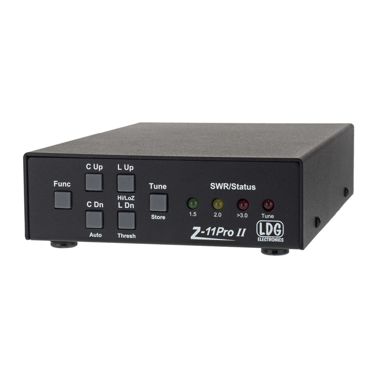
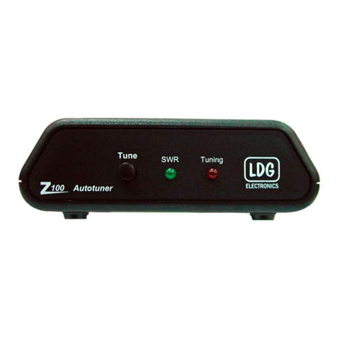
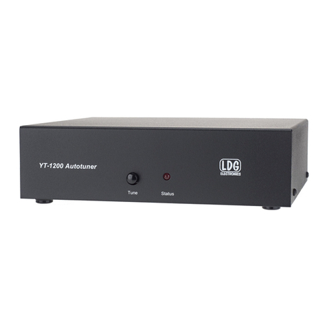
On the front panel there is one pushbutton and two LED indicator lights.
TUNE Button: Initiates either a memory tune or a full tune, and also toggles the tuner
between “active” and “bypass” modes.
SWR LED: Lights or blinks to indicate SWR condition.
STATUS LED: Lights to give feedback on button activation; lights during tuning; provides
tuning status at the end of a tuning cycle.

7
Rear Panel Connectors
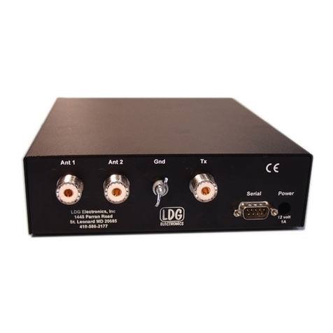
The rear panel of the Z-100A features four connectors.
ANT: Connect the 50Ω coax antenna feedline to the standard SO-239 connector.
GND (wing nut): Connect to antenna system ground if needed.
RADIO: Connect the 50Ω coax jumper cable from this standard SO-239 connector to the
Antenna jack on the rear of the transceiver.
INTERFACE: This 6-pin mini-DIN connector connects to the radio interface cable. DC power
is also supplied via this connector. Be sure to turn off the transceiver before connecting or
removing cables.

8
Operating Hints
Transceiver Tuner Status Indication
Different models of ICOM transceivers indicate the status of the external tuner with slight
variation. Most will show a graphical or textual icon on the screen to indicate that the tuner
is active and has properly tuned. For example, the IC-7000 displays a blinking icon
while tuning, and a solid icon when tuning is complete. This icon disappears when
the tuner is bypassed, and blinks if a tuning cycle failed to find a good match. Other ICOM
transceivers behave similarly. Consult your transceiver operating manual’s external tuner
section for more information. When in doubt key the radio in AM and press the Tune button
on the LDG tuner.
Radio Interface Cables
There are a variety of three foot interface cables available.
-Press Button on Tuner or Radio
oIC-100 ICOM AH-3 or AH-4 Compatible
-Press Button on Tuner
oIC-105 ALINCO EDX-2 Compatible, DX-70, DX-77
oIC-108 YAESU FT-100, 857, 897, 891, 991
oIC-109 YAESU FT-450, 950, 1200, FTdx10
oIC-115 YAESU FTdx101, 3000
-Key Radio and Press Button on Tuner
oIC-105 ALINCO SR8T, SR9T
oIC-106 KENWOOD AT-300 Compatible
-Power Only
oIC-104 Power, Ground, Key, Start


A608
PCS1
MINIDIN6PINPLUG,NICKELPLATED
MINI DIN6PINPLUG
XXXXXXXXXX3 XXXXXXXXXX2
1)100%OPENSHORT&MISSWIRETEST
2)INSULATIONRESISTANCE:DC300V50MOHM
3)CONDUCTORRESISTANCE:5OHM
ELECTRICALTEST
MOLDNOPART REVISIONNOTEDATEREV NO
MM
SEE"CABLECONSTRUCTION"
CABLEXXXXXXXXXX1 UNITQ'TYMATERIAL/FINISHPARTNAMEMATERIALNONO.
0.14
0.20
0.30
0.40
0.50>300~600
>120~300
>30~120
>6~30
>0~6 TOLERANCEPANGE
UNLESSOTHERSPECIFIED
STANDARDTOLERANCE LIMITS
行
日期 2020.8.7
1/1
1:1MM
0.1
比例
頁數圖法
單位
料號
品
料號
編號
文件
版次
客戶 Hu
制圖
審核
核准
1000 30
1
IC-105HG
2
CTP036/037
MINI DIN6PINPLUG
4
1
WIREADDRESS
P1 2
5
6
CABLECONSTRUCTION
BLACK
MATERIAL
CONSTRUCT mm/NO.
MATERIAL
O.D. mm
MATERIAL
CONSTRUCT mm/NO.
MATERIAL
O.D. mm
COLOR
SPEC
ITEM
INSULATION
SHIELD
PVCJACKET
CENTER
CONDUCTOR CCA
0.20*7
PVC/4C
1.30 0.05
CCA
0.20*7
PVC
6.0 0.2
MATERIAL FOIL
FOIL
INNERMOLD
OUTTERMOLD 45PPVCBLACK
PETRANSPARENT 2 G
2 G4 XXXXXXXXXX
34
PACKAGE
100PCS/PEBAG
P2
25 55
1
TERMINAL 4
HOUSING 1 PCS
PCS
XXXXXXXXXX5
6 XXXXXXXXXX
65
P2
1
5
3
RED
BLACK
BLUE
GREEN
6
2
135
P1
4
7XXXXXXXXXX SHIRNKTUBE OD:7.0MMBLACKL=15MM 1PCS
7
1*5PHOUSING
TINPLATED
REF
REF

A608
PCS1
MINIDIN6PINPLUG,NICKELPLATED
MINIDIN6PIN PLUG
XXXXXXXXXX3 XXXXXXXXXX2
1)100%OPENSHORT&MISSWIRETEST
2)INSULATIONRESISTANCE:DC300V50MOHM
3)CONDUCTORRESISTANCE:5OHM
ELECTRICALTEST
MOLDNOPART REVISIONNOTEDATEREVNO
MM
SEE"CABLECONSTRUCTION"
CABLEXXXXXXXXXX1 UNITQ'TYMATERIAL/FINISHPARTNAMEMATERIALNONO.
0.14
0.20
0.30
0.40
0.50>300~600
>120~300
>30~120
>6~30
>0~6 TOLERANCEPANGE
UNLESSOTHERSPECIFIED
STANDARDTOLERANCE LIMITS
行
日期 2020.08.14
1/1
1:1MM
0.1
比例
頁數圖法
單位
料號
品
料號
編號
文件
版次
客戶 Hu
制圖
審核
核准
1000 30
1
IC-106HG
2
P1
CTP036/037
MINIDIN6PINPLUG
WIREADDRESS
INNERMOLD
OUTTERMOLD 45PPVCBLACK
PETRANSPARENT 2 G
2 G4 XXXXXXXXXX
3 4
PACKAGE
100PCS/PEBAG
P2
25 5
TERMINAL 3
HOUSING 1 PCS
PCS
XXXXXXXXXX5
6XXXXXXXXXX
65
AL/MY
MATERIAL
FOIL
4.7 0.2
PVC
0.18/21
CCA
1.75 0.05/2C
PVC
0.18/21
CCACENTER
CONDUCTOR
PVCJACKET
SHIELD
INSULATION
ITEM
COLOR mm
O.D.
MATERIAL
mm/NO.
CONSTRUCT
MATERIAL mm
O.D.
MATERIAL mm/NO.
CONSTRUCT
MATERIAL
BLACK
CABLECONSTRUCTION
6
4
2
135
4
1
P1 1
6
P2
3
6
RED
BLACK
SPIRAL
2*3PHOUSINGMALE,(E130H-2*3)
TINPLATED(E130T2)
1
3
4
6
REF

100PCS/CARTON
3
2
4
6
11
3
P2P3
P1
3 2 1
P3
P2
SPIRAL
SPIRAL
BLACK
RED
CTS021
SR
7
2
100 10
1000 30
1
SPEC1
SPEC2
SPEC1
G
BLACK
SPEC2
CCA
0.18/21
PVC
1.75 0.05/1C
CCA
0.12*45
PVC
3.0 0.1
/AL/MYMATERIAL
FOIL
9.5
14.8 0.5
39.4
A608
XXXXXXXXXX4
PCS1
XXXXXXXXXX3 XXXXXXXXXX2
1)100%OPENSHORT&MISSWIRETEST
2)INSULATIONRESISTANCE:DC300V50MOHM
3)CONDUCTORRESISTANCE:5OHM
ELECTRICALTEST
MOLDNOPART REVISIONNOTEDATEREV NO
MM
SEE"CABLECONSTRUCTION"
CABLEXXXXXXXXXX1 UNITQ'TYMATERIAL/FINISHPARTNAMEMATERIALNONO.
0.14
0.20
0.30
0.40
0.50>300~600
>120~300
>30~120
>6~30
>0~6 TOLERANCEPANGE
UNLESSOTHERSPECIFIED
STANDARDTOLERANCE LIMITS
行
日期 2020.09.29
1/1
1:1MM
0.1
比例
頁數圖法
單位
料號
品
料號
編號
文件
版次
客戶 peter
制圖
審核
核准
PACKAGING
IC-108HG
WIREADDRESS
3.5PLUG CT3002
XXXXXXXXXX5
4.7 0.1
PVC
0.18/21
CCA
1.75 0.05/2C
PVC
0.18/21
CCACENTER
CONDUCTOR
PVCJACKET
SHIELD
INSULATION
ITEM SPEC1
COLOR mm
O.D.
MATERIAL
mm/NO.
CONSTRUCT
MATERIAL mm
O.D.
MATERIAL mm/NO.
CONSTRUCT
MATERIAL
BLACK
CABLECONSTRUCTION
XXXXXXXXXX6
1
2
P1
6
6
4
2
135
MINI DIN8PINPLUG CTP011/068
852
6 3 1
35.6 8.5
2.5
CTP036/037
MINI DIN6PINPLUG
MINIDIN8PINNICKELPLATED,BLACK
MINI DIN8PINPLUG
MINIDIN6PINPLUG,NICKELPLATED
MINI DIN6PINPLUG
PCS1
3.5STPLUG 3.5MMSTEREONICKELPLATED PCS1
INNERMOLD
OUTTERMOLD 45PPVCBLACK
PETRANSPARENT 4 G
4
3
5
4
65
XXXXXXXXXX7 SRMOLD 45PPVCBLACK 4 G
XXXXXXXXXX8
6
1 PCS
6.5*8*1.0mmPCB
PCB
8
REF
REF
REF

A608
PCS1
MINIDIN6PINPLUG,NICKELPLATED
MINI DIN6PINPLUG
XXXXXXXXXX3 XXXXXXXXXX2
1)100%OPENSHORT&MISSWIRETEST
2)INSULATIONRESISTANCE:DC300V50MOHM
3)CONDUCTORRESISTANCE:5OHM
ELECTRICALTEST
MOLDNOPART REVISIONNOTEDATEREV NO
MM
SEE"CABLECONSTRUCTION"
CABLEXXXXXXXXXX1 UNITQ'TYMATERIAL/FINISHPARTNAMEMATERIALNONO.
0.14
0.20
0.30
0.40
0.50>300~600
>120~300
>30~120
>6~30
>0~6 TOLERANCEPANGE
UNLESSOTHERSPECIFIED
STANDARDTOLERANCE LIMITS
行
日期 2020.8.7
1/1
1:1MM
0.1
比例
頁數圖法
單位
料號
品
料號
編號
文件
版次
客戶 Hu
制圖
審核
核准
1000 30
1
IC-109HG
6
4
2
135
2
P1
CTP036/037
MINI DIN6PINPLUG
4
1
WIREADDRESS
P1 1
6
INNERMOLD
OUTTERMOLD 45PPVCBLACK
PETRANSPARENT 4 G
4 G
4XXXXXXXXXX
4 5
PACKAGE
200PCS/PEBAG
P2
XXXXXXXXXX5
P2
3
10
RED
BLACK
SPIRAL
810
7
4
13
AL/MYMATERIAL
FOIL
4.7 0.2
PVC
0.18/21
CCA
1.75 0.05/2C
PVC
0.18/21
CCACENTER
CONDUCTOR
PVCJACKET
SHIELD
INSULATION
ITEM
COLOR mm
O.D.
MATERIAL
mm/NO.
CONSTRUCT
MATERIAL mm
O.D.
MATERIAL mm/NO.
CONSTRUCT
MATERIAL
BLACK
CABLECONSTRUCTION
PCS1
MINI DIN10PINPLUG MINI DIN10PINPLUG,NICKELPLATED,
5
CTP069/070
MINI DIN10PINPLUG
4 3
REF
REF

A608
PCS1
MINIDIN6PINPLUG,NICKELPLATED
MINI DIN6PINPLUG
XXXXXXXXXX3 XXXXXXXXXX2
1)100%OPENSHORT&MISSWIRETEST
2)INSULATIONRESISTANCE:DC300V50MOHM
3)CONDUCTORRESISTANCE:5OHM
ELECTRICALTEST
MOLDNOPART REVISIONNOTEDATEREV NO
MM
SEE"CABLECONSTRUCTION"
CABLEXXXXXXXXXX1 UNITQ'TYMATERIAL/FINISHPARTNAMEMATERIALNONO.
0.14
0.20
0.30
0.40
0.50>300~600
>120~300
>30~120
>6~30
>0~6 TOLERANCEPANGE
UNLESSOTHERSPECIFIED
STANDARDTOLERANCE LIMITS
行
日期 2020.8.7
1/1
1:1MM
1.0
比例
頁數圖法
單位
料號
品
料號
編號
文件
版次
客戶 HU
制圖
審核
核准
1000 30
1
IC-115HG
6
4
2
135
2
P1
CTP036/037
MINI DIN6PINPLUG
4
1
WIREADDRESS
P1 1
6
INNERMOLD
OUTTERMOLD 45PPVCBLACK
PETRANSPARENT 4 G
4 G
4XXXXXXXXXX
4 5
PACKAGE
100PCS/PEBAG
P2
XXXXXXXXXX5
P2
3
11
RED
BLACK
SPIRAL
AL/MYMATERIAL
FOIL
4.7 0.2
PVC
0.18/21
CCA
1.75 0.05/2C
PVC
0.18/21
CCACENTER
CONDUCTOR
PVCJACKET
SHIELD
INSULATION
ITEM
COLOR mm
O.D.
MATERIAL
mm/NO.
CONSTRUCT
MATERIAL mm
O.D.
MATERIAL mm/NO.
CONSTRUCT
MATERIAL
BLACK
CABLECONSTRUCTION
XXXXXXXXXX6
3
PCS1
DP15PINPLUG,NICKELPLATED,PING/F
DBPLUG
G12
ABS SHIELD,GREY COLOR
SHIELD
6
REF
REF

1
G
6
A
G6A
Low Signal Relay
World's Standard Model G6A!
• Resistant to electromagnetic interference,
enables high-density mounting.
• Impulse withstand voltage of 1,500V meets FCC
requirements.
• Gold-clad twin-contacts provide short contact
bounce in addition to its high contact reliability.
• A variety of products that cover a wide range of
use.
■Model Number Legend
■Ordering Information
●UL/C-UL Certified Models
Note: When ordering, add the rated coil voltage to the model number.
Example: G6A-274P-ST-US DC3
However, the notation of the coil voltage on the product case as well as on the packing will be marked as @@ VDC.
RoHS Compliant
Relay Function Classification Contact form Model Rated coil voltage (VDC) Minimum packing unit
Single-side Stable
Type
Standard
DPDT (2c)
G6A-274P-ST-US 3, 4.5, 5, 6, 9, 12, 24
25 pcs/tube
48
Low-sensitivity G6A-274P-ST40-US 3, 5, 6, 9, 12, 24
48
High-sensitivity G6A-274P-ST15-US 3, 5, 6, 9, 12, 24
48
Single-winding
Latching Type Standard G6AU-274P-ST-US 3, 4.5, 5, 6, 9, 12, 24
48
Double-winding
Latching Type
Standard G6AK-274P-ST-US 3, 4.5, 5, 6, 9, 12, 24
48
Low-sensitivity G6AK-274P-ST40-US 3, 5, 6, 9, 12, 24
48
■Application Examples
• Telecommunication equipment
• Security equipment
• Test & measurement equipment
G6A@-@@@@-@-@
1234567
5. Terminal Shape
P: PCB Terminals
6. Classification
7. Approved Standards
None : Standard
ST : Stand-off 0.64 mm
15 : High-sensitivity (150 mW)
40 : Low-sensitivity
(Single-side Stable: 400 mW
Double-winding Latching: 360 mW)
None : Standard
US : UL/C-UL
1. Relay Function
2. Contact Form
2: DPDT (2c)
3. Contact Type
7: Bifurcated crossbar Ag (Au-Alloy)
4. Protective Structure
4: Fully sealed
None : Single-side stable
U : Single-winding latching
K : Double-winding latching
Rated coil voltage

2
G6A Low Signal Relay
G
6
A
■Ratings
●Coil: Single-side Stable (Standard Models)
Note1. The rated current and coil resistance are measured at a coil temperature of 23°C with a tolerance of ±10%.
2. Operating characteristics are measured at a coil temperature of 23°C.
3. The maximum voltage is the highest voltage that can be imposed on the relay coil.
●Coil: Single-side Stable (Low-sensitivity Models)
Note1. The rated current and coil resistance are measured at a coil temperature of 23°C with a tolerance of ±10%.
2. Operating characteristics are measured at a coil temperature of 23°C.
3. The maximum voltage is the highest voltage that can be imposed on the relay coil.
●Coil: Single-side Stable (High-sensitivity Models)
Note1. The rated current and coil resistance are measured at a coil temperature of 23°C with a tolerance of ±10%.
2. Operating characteristics are measured at a coil temperature of 23°C.
3. The maximum voltage is the highest voltage that can be imposed on the relay coil.
●Coil: Single-winding Latching
Note1. The rated current and coil resistance are measured at a coil temperature of 23°C with a tolerance of ±10%.
2. Operating characteristics are measured at a coil temperature of 23°C.
3. The maximum voltage is the highest voltage that can be imposed on the relay coil.
Contact form Rated voltage Rated current
(mA)
Coil resistance
(Ω)
Must operate voltage
(V)
Must release voltage
(V)
Max. voltage
(V) Power consumption
(mW)
% of rated voltage
DPDT (2c)
3 VDC 66.7 45
70% max. 10% min. 200%
(at 23°C)
Approx. 200
4.5 VDC 44.6 101
5 VDC 40.0 125
6 VDC 33.3 180
9 VDC 22.2 405
12 VDC 16.7 720
24 VDC 8.3 2,880
48 VDC 4.9 9,750 Approx. 235
Contact form Rated voltage Rated current
(mA)
Coil resistance
(Ω)
Must operate voltage
(V)
Must release voltage
(V)
Max. voltage
(V) Power consumption
(mW)
% of rated voltage
DPDT (2c)
3 VDC 133.3 22.5
70% max. 10% min. 150%
(at 23°C) Approx. 400
5 VDC 80 62.5
6 VDC 66.7 90
9 VDC 44.3 203
12 VDC 33.3 360
24 VDC 16.7 1,440
48 VDC 8.3 5,760
Contact form Rated voltage Rated current
(mA)
Coil resistance
(Ω)
Must operate voltage
(V)
Must release voltage
(V)
Max. voltage
(V) Power consumption
(mW)
% of rated voltage
DPDT (2c)
3 VDC 50 60
80% max. 10% min. 200%
(at 23°C) Approx. 150
4.5 VDC 33.3 135
5 VDC 30 167
6 VDC 25 240
9 VDC 16.7 540
12 VDC 12.5 960
24 VDC 6.3 3,840
48 VDC 3.2 15,000
Contact form Rated voltage Rated current
(mA)
Coil resistance
(Ω)
Set voltage (V) Reset voltage (V) Max. voltage (V) Power consumption
(mW)
% of rated voltage
DPDT (2c)
3 VDC 33.7 89
70% max. 70% max. 200%
(at 23°C)
Approx. 100
5 VDC 20 250
6 VDC 16.7 360
9 VDC 11.1 810
12 VDC 8.3 1,440
24 VDC 4.2 5,760
48 VDC 2.5 19,000 Approx. 120

3
G6A Low Signal Relay
G
6
A
●Coil: Double-winding Latching (Standard Models)
Note1. The rated current and coil resistance are measured at a coil temperature of 23°C with a tolerance of ±10%.
2. Operating characteristics are measured at a coil temperature of 23°C.
3. The maximum voltage is the highest voltage that can be imposed on the relay coil.
●Coil: Double-winding Latching (Low-sensitivity Models)
Note1. The rated current and coil resistance are measured at a coil temperature of 23°C with a tolerance of ±10%.
2. Operating characteristics are measured at a coil temperature of 23°C.
3. The maximum voltage is the highest voltage that can be imposed on the relay coil.
●Contacts
Contact form Rated voltage Rated current
(mA)
Coil resistance
(Ω)
Set voltage (V) Reset voltage (V) Max. voltage (V) Power consumption
(mW)
% of rated voltage
DPDT (2c)
3 VDC 66.7 45
70% max. 70% max. 200%
(at 23°C)
Approx. 200
4.5 VDC 40.2 112
Approx. 180
5 VDC 36 139
6 VDC 30 200
9 VDC 20 450
12 VDC 15 800
24 VDC 7.5 3,200
48 VDC 4.2 11,520 Approx. 200
Contact form Rated voltage Rated current
(mA)
Coil resistance
(Ω)
Set voltage (V) Reset voltage (V) Max. voltage (V) Power consumption
(mW)
% of rated voltage
DPDT (2c)
3 VDC 120 25
70% max. 70% max. 150%
(at 23°C) Approx. 360
4.5 VDC 79.9 56.3
5 VDC 72.5 69
6 VDC 60 100
9 VDC 40 225
12 VDC 30 400
24 VDC 15 1,600
48 VDC 7.5 6,400
Load
Item
Resistive load
Inductive load
Contact type Bifurcated crossbar
Contact material Ag (Au-Alloy) contact
Rated load 0.5 A at 125 VAC;
2 A at 30 VDC
0.3 A at 125 VAC;
1 A at 30 VDC
Rated carry current 3 A
Max. switching voltage 250 VAC, 220 VDC
Max. switching current 2 A 1 A
cosφ= 0.4;
L/R = 7 ms
()

4
G6A Low Signal Relay
G
6
A
■Characteristics
Note: The data shown above are initial values.
*1. The contact resistance was measured with 10 mA at 1 VDC with a voltage drop method.
*2. The insulation resistance was measured with a 500 VDC megohmmeter applied to the same parts as those used for checking the dielectric strength (except
between the set and reset coil).
*3. This value was measured at a switching frequency of 60 operations/min and the criterion of contact resistance is 50 Ω. This value may vary, depending on
switching frequency, operating conditions, expected reliability level of the relay, etc. It is always recommended to double-check relay suitability under actual load
conditions.
Item Classification Single-side Stable Single-winding Latching Double-winding Latching
Contact resistance *1 50 mΩmax.
Operate (set) time 5 ms max. 5 ms max.
Release (reset) time 3 ms max. 5 ms max.
Min. set/reset signal width −10 ms
Insulation resistance *2 1,000 MΩmin. (at 500 VDC); except for set-reset
Dielectric
strength
Between coil and contacts 1,000 VAC, 50/60 Hz for 1 min
Between contacts of the
same polarity 1,000 VAC, 50/60 Hz for 1 min
Between contacts of
different polarity 1,000 VAC, 50/60 Hz for 1 min
Between set and reset
coils −−250 VAC, 50/60 Hz for 1 min
Impulse withstand voltage 1,500 V (10 ×160 μs) (conforms to FCC Part 68)
Vibration
resistance
Destruction 10 to 55 to 10 Hz, 2.5 mm single amplitude (5 mm double amplitude)
Malfunction 10 to 55 to 10 Hz, 1.65 mm single amplitude (3.3 mm double amplitude)
Shock
resistance
Destruction 1,000 m/s2
Malfunction 500 m/s2300 m/s2
Durability Mechanical 100,000,000 operations min. (at 36,000 operations/hr)
Electrical 500,000 operations min. (at 1,800 operations/hr)
Failure rate (P level) *3 10 μA at 10 m VDC
Ambient operating temperature -40°C to 70°C (with no icing or no condenstion)
Ambient operating humidity 5% to 85%
Weight Approx. 3.5 g
Other manuals for Z-100A
1
Table of contents
Other LDG Tuner manuals