LEAB PowAirBox A User manual

LEAB Automotive GmbH
Thorshammer 6
DE-24866 Busdorf
User Manual
Version: 3.6
Issue date: 15.04.2019
PowAirBox®
Type A, Type B (12 V, 24 V, 230 V)
Supply system for electricity and compressed air with automatic ejection
User Manual

Welcome
With the LEAB PowAirBox, you have opted for a modern and technically
innovative supply system for electricity and compressed air. Read this
manual carefully before installing and commissioning, and retain it for
future reference.
If you have any suggestions or comments about this manual, please let us
Our website, www.leab.eu, contains further information on the device
(including data sheets and installation videos) as well as the latest version
of the manual. Here you will also find information about optional
accessories or variants of your device.

Table of Contents
1About this Manual ................................................................................ 1
2General Safety ...................................................................................... 2
3About the PowAirBox ........................................................................... 2
4Installation of the Supply Unit .............................................................. 4
5Installation of the Coupling .................................................................. 4
6Package Contents ................................................................................. 5
7Assembly and Installation..................................................................... 5
7.1 Assembling and Connecting the Supply Unit .................................. 6
7.1.1 Creating a Body Cutout ......................................................... 7
7.1.2 Connecting and Assembling the Supply Unit ........................ 8
7.2 Connecting the Coupling................................................................. 9
7.3 Optional: Mounting the Ceiling Bracket ....................................... 10
8Operation ........................................................................................... 10
9Cleaning and Maintenance................................................................. 12
10 Technical Specifications...................................................................... 12
11 Connection Diagram ........................................................................... 13
12 Disposal .............................................................................................. 15
13 Accessories and Spare Parts ............................................................... 15
14 EU Declaration of Conformity............................................................. 15
15 Warranty............................................................................................. 16

About this Manual User Manual
Page 1 of 16
1About this Manual
The technical data, information and illustrations are carefully compiled and
correspond to the state of the art at the time of printing. LEAB reserves the
right to change devices and documentation without prior notice at any time
in accordance with technical requirements and new developments.
Throughout the manual, you will be alerted to warnings and safety notices
about potential hazards associated with handling the device. The colours
and signal words indicate the severity of the hazard:
Signal word
Meaning
DANGER
Warns of imminent danger resulting in death or
serious injury.
WARNING
Warns of a potentially dangerous situation that
can result in death or serious injury.
CAUTION
Warns of a potentially dangerous situation that
can result in moderate or minor injuries.
NOTICE
Warns of a potentially dangerous situation that
can result in material and environmental
damage.
In this manual you will also find the following symbols:
Shows you useful tips and information about the device.
Indicates a mandatory requirement for the following
instruction.
Shows the result of an instruction.
It is prohibited to copy, duplicate, translate or otherwise pass on the
content of this manual to third parties without the express written
permission of LEAB.

General Safety User Manual
Page 2 of 16
2General Safety
This manual supports safe handling of the device. Use the device solely in
accordance with its intended use:
The LEAB PowAirBox is a system for supplying electricity and compressed
air to emergency vehicles.
Assembly and installation should only be carried out by qualified
electricians. Any modifications to the device or its components are
prohibited and do not conform to its intended use. Only use original LEAB
or LEAB-approved accessories.
When installing and using the PowAirBox, observe the basic safety
instructions:
Electric current hazard: Before operation, make sure there are no
open or damaged cables.
Replace defective parts or damaged cables immediately.
Only use the PowAirBox within the specified voltage limits.
Device defect and faulty ejection due to control modules: Do not
connect control modules directly to the PowAirBox. Always use an
additional relay for this purpose.
Reverse polarity can damage the unit: Before operation, make sure
that all cables are connected correctly in accordance with the
connection diagram (see page 13).
3About the PowAirBox
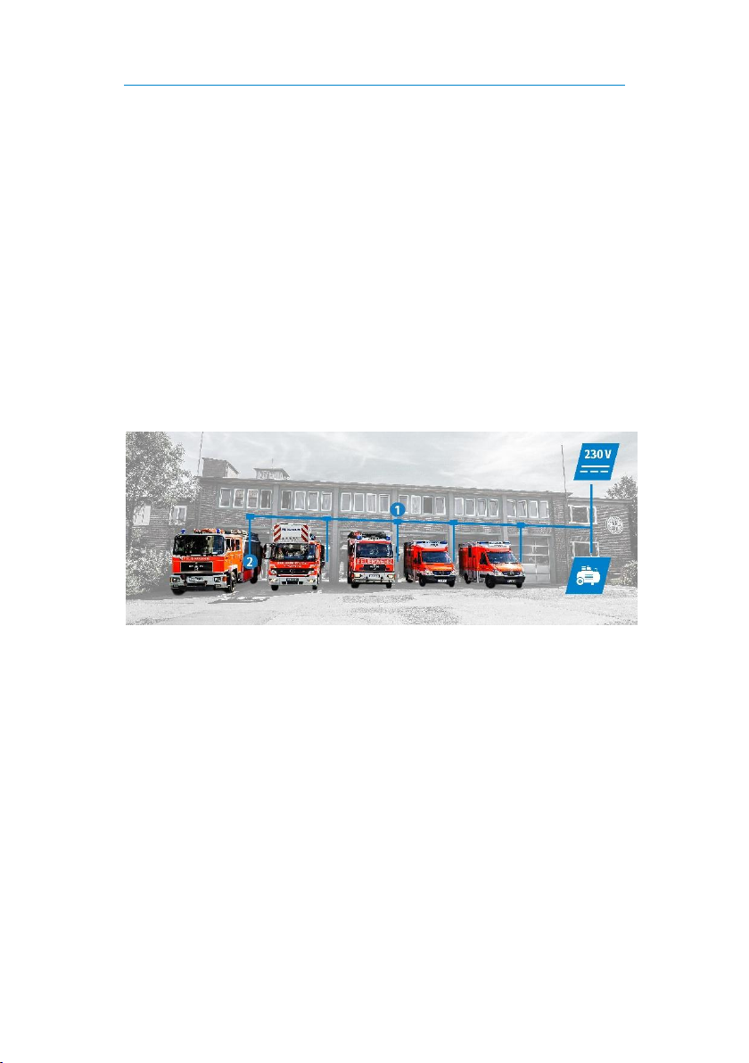
With the LEAB PowAirBox, the supply is fed in via a special plug connection
and combines electricity and compressed air in a single cable. When the
vehicle engine is started, the coupling is automatically disconnected from
the vehicle and the protective cover closes automatically. The status display
provides reliable information about the current charge status of the
connected battery and the charging process. Two auxiliary contacts
installed in the PowAirBox serve to establish a start locking mechanism.

About the PowAirBox User Manual
Page 3 of 16
There are two types of the PowAirBox:
PowAirBox Type A (supply of electricity and compressed air)
PowAirBox Type B (supply of electricity)
Both types are available for 12 V, 24 V or 230 V. Due to coding, supplies and
couplings of different voltages are not interchangeable. However, types A
and B are compatible at the same voltage and can be inserted together to
supply a vehicle with electricity. There is no air supply when doing this, but
also no air loss. The supply unit and coupling are supplied with
prefabricated connecting cables. The connection in the vehicle is made via
lockable plug-in connectors.
The PowAirBox System
When installing the PowAirBox system in the vehicle depot, LEAB
recommends direct connection to the electricity and compressed air
distribution with the LEAB PowAirBox ceiling bracket . The combination
cable (electricity and compressed air) leads from the ceiling bracket to the
supply unit installed in the vehicle . LEAB also recommends the use of
LEAB ABC, LEAB CPC or LEAB Champ Pro built-in chargers.
For vehicle depots without a complete PowAirBox system, LEAB also offers
supply adapters with different plug connections (e.g. CEE).

Installation of the Supply Unit User Manual
Page 4 of 16
4Installation of the Supply Unit
Number
Description
1
Connector A: Ejection
2
Connector B: Battery
3
Connector C: Start locking mechanism
4
Compressed air hose (with Type A)
5
Load output
6
Protective cover
7
Operating display
5Installation of the Coupling
Number
Description
1
Combination cable
2
Coupling socket

Package Contents User Manual
Page 5 of 16
6Package Contents
Scope of delivery of the supply unit
No.
Type A
Type B
PowAirBox supply unit
x1
1x
Connection cable for connector A, B, C
x3
3x
Connection cable for load output
x1
1x
Compressed air hose
x1
-
Connector, compressed air (IQS)
x1
-
Mounting frame with seal
x1
1x
Body seal
x1
1x
Threaded pin
x6
6x
M4 screw (Allen 2.5 mm)
x6
6x
Adhesive tapes for mounting frame
x2
2x
User Manual
x1
1x
You can order spare parts and accessories either through your
dealer or directly from LEAB. Just visit our webshop at
www.leab.eu or call us on:
+49(0) 4621 9 78 60-110.
Scope of delivery of the coupling
No.
Type A
Type B
PowAirBox coupling
x1
1x
User Manual
x1
1x
7Assembly and Installation
This chapter describes the assembly and installation of the PowAirBox.
An installation video and FAQs can be found at
www.powairbox.de.

Assembly and Installation User Manual
Page 6 of 16
7.1 Assembling and Connecting the Supply Unit
Notes on the Assembly Site
NOTICE
Device defect due to incorrect installation
Choose an upright and level surface.
Choose a site that has minimum dust and is protected from jet
water.
Ensure that there is sufficient space at the assembly site (see
illustration).

Assembly and Installation User Manual
Page 7 of 16
7.1.1 Creating a Body Cutout
a) Undo the 6 M4 screws (Allen 2.5
mm) from the power supply.
b) Remove the mounting frame.
c) Place the mounting frame at the
assembly site.
d) Mark the inside contour of the frame
and the 6 screw holes.
a) Cut out the marked area.
b) Drill the marked holes (4.5 mm - 5
mm).
a) Screw the 6 threaded pins by hand
into the smooth side of the mounting
frame.
b) Glue the 2 adhesive strips to the
smooth side of the mounting frame.
c) Check that the threaded pins fit
through the holes from the inside.
d) To prevent corrosion, seal the cut
surfaces and boreholes.
e) Remove the protective film from the
adhesive strips.
f) Glue the mounting frame into the
cutout from the inside.
The body cutout is created and you can connect the supply
unit.

Assembly and Installation User Manual
Page 8 of 16
7.1.2 Connecting and Assembling the Supply Unit
WARNING
Danger of pressure loss in the compressed air tank.
Never heat the compressed air hose.
Before connecting the supply unit:
1. Lay the connecting cables supplied and the compressed air
hose in the vehicle.
2. Install suitable fuses for the connection cables A and B (see
connection diagram on page 13).
3. Attach the connection cables to the vehicle installation.
4. Connect the compressed air hose to the vehicle’s compressed
air tank.
Warning: To avoid pressure loss, make sure that a non-return
valve is installed on the vehicle side.
Connecting the Supply Unit
A detailed connection diagram can be found on page 13.
Number
Description
1
Connector A: Ejection
2
Connector B: Battery
3
Connector C: Start
locking mechanism
4
Compressed air hose
(with Type A)
5
Load output
1. Connect terminal 50 (starter motor control) or terminal 15 (switched
ignition plus) with connector A . The pulse duration of the start
signal must be at least 2 seconds (for delayed ejection).
Notice: To avoid a device defect, do not use any tools for the
connection and make sure that the polarity of the connections is
correct (see connection diagram on page 13).
2. Connect the starter battery for the supply voltage of the PowAirBox
to connector B .
3. Optional: Use the two bridged auxiliary contacts at connector C to
create a start locking mechanism.
Notice: Max. voltage: 24 V (5 A)

Assembly and Installation User Manual
Page 9 of 16
4. Connect the consumers (e.g. charger) to the load output .
5. With type A: Connect the compressed air hose to the compressed
air hose already installed in the vehicle.
Warning: Only use the IQS connector supplied to connect the
compressed air hoses.
Assembling the Supply Unit
Before assembling the supply unit:
Check that all cables are correctly connected on the back of the
PowAirBox.
1. Push the supply unit into the body
cutout.
2. Remove the 6 threaded pins.
3. Insert the 6 M4 screws (Allen 2.5 mm)
and tighten them until the body seal is
flat.
4. To prevent unintentional loosening of
the screws, apply a screw locking
lacquer.
The PowAirBox supply unit is assembled and ready to use.
7.2 Connecting the Coupling
NOTICE
Device defect due to faulty ejection
Do not use cable winders or similar in the vehicle depot.
Be sure that the combination cable is not under power when
connecting it.
The auxiliary contacts in the coupling are bridged at the
factory in order to establish a start locking mechanism.
Connect the coupling lines with the power and compressed air distribution
at the vehicle depot. (see connection diagram on page 13).
The complete PowAirBox system is installed and ready to use.

Operation User Manual
Page 10 of 16
7.3 Optional: Mounting the Ceiling Bracket
To ensure smooth operation, ensure that the coupling does not
touch the depot floor when unplugged. LEAB recommends a
distance of approx. 70 cm from the depot floor.
1. Select a mounting location at a lateral distance of approx. 30 cm from
the vehicle.
2. Install the mounting frame on the depot ceiling.
3. Guide the cover onto the coupling’s combination cable.
4. Insert the combination cable through the bracket opening on the
mounting frame.
5. Connect the coupling lines with the power and compressed air
distribution at the vehicle depot. (see connection diagram on page 13).
6. Slide the cover over the mounting frame and fasten it with the
screw cap.
The complete PowAirBox system
is installed and ready to use.
8Operation
NOTICE
Contact erosion when pulling under load
Do not pull the coupling out of the supply unit when under load.
LEAB recommends using only automatic ejection.
1. Turn the protective cover sideways
pointing upwards.
Notice: Observe the direction arrow
and do not use the protective cover
as a bracket for jackets or the like.
If necessary, remove individual sealing rings from the bracket
opening.

Operation User Manual
Page 11 of 16
2. Plug the coupling into the supply unit.
Notice: When plugging in, make sure that the nose of the coupling is
facing to the blue dot on the PowAirBox.
The voltage input is provided at the load output of the
supply unit. Connected consumers are supplied. The status
display indicates the status of the PowAirBox and the
connected battery (see illustration).
Number
Function
Battery voltage
12-V battery
24-V battery
1
Chaser: Battery is fully
charged
> 13.3 V
> 26.5 V
2
Operating display:
Current voltage of the
battery.
12.6 V …
13.2 V
25.2 V …
26.4 V
3
12.2 V …
12.5 V
24.4 V …
25.1 V
4
12.1 V …
11.6 V
23.1 V …
24.3 V
5
Low voltage alarm
< 11.5 V
< 23.0 V
Ejecting the coupling
To eject the coupling automatically and interrupt the electricity and
compressed air supply, start the vehicle engine.
The automatic ejection has a delay to protect the contacts. The
delay is so minimal that there is no disturbance to driving
operation.

Cleaning and Maintenance User Manual
Page 12 of 16
9Cleaning and Maintenance
WARNING
Injury from electric shock
Before doing any work, make sure that the PowAirBox system is de-
energised.
NOTICE
Strong jet water can damage the unit
Do not aim the pressure washer or other devices directly at the
PowAirBox supply unit.
Regular Activities
Always check the PowAirBox for external damage before using it.
Clean the coupling, power supply and cable regularly.
Protect the coupling and cable from being run over, getting wet and
other liquids.
Regularly check the screw connections of the supply unit to the vehicle
body.
10 Technical Specifications
Technical Specifications
Nominal voltage, supply unit
12 V, 24 V, 230 V (depending on variant)
Supply current, max.
16 A (AC), 20 A (DC)
Voltage, vehicle battery
12 V or 24 V (universal)
Compressed air (Type A), max.
13 bar
IP rating
IP55
Protection class
II
Cable length, supply
4 m
Auxiliary contacts
2
Operating display
LED
Low voltage alarm
LED + acoustic (interval: 6 s)
Material
Polyamide, glass fibre reinforced (PA6
GF30)
Weight, supply
1.2 kg
Installation depth, supply
121 mm
Dimensions, supply
110 x 193 x 145 mm

Connection Diagram User Manual
Page 13 of 16
11 Connection Diagram

Connection Diagram User Manual
Page 14 of 16
Connection Diagram
1
PowAirBox supply unit
2
Connector C: Start locking mechanism
The auxiliary contacts in the coupling are bridged at the
factory.
Notice: Max. voltage: 24 V (5 A)
3
Load output
2-pin with direct current (12 V and 24 V)
3-pin with alternating current (230 V)
4
Connector A: Ejection
Connect the red wire to terminal 50 or terminal 15 for
the transmission of the start signal.
Connect the black wire to the negative terminal of the
starter battery.
Install a fuse (in accordance with ISO 8820-3):
12 V: 3 A
24 V: 6 A
5
Connector B: Battery
Connect the red wire to the positive terminal of the
starter battery.
Connect the black wire to the negative terminal of the
starter battery.
Install a fuse (in accordance with ISO 8820-3):
12 V: 1 A
24 V: 1 A
6
PowAirBox coupling
Connect the wires of the electrical cable (for type B) or
the combination cable (for type A) with the power and
compressed air distribution in the vehicle depot.
The wires are numbered accordingly in the combination
cable (for type A).

Disposal User Manual
Page 15 of 16
12 Disposal
Dispose of the device in accordance with the Waste Electrical and
Electronic Equipment Regulations (WEEE).
The device must not be disposed of with household waste.
Take it to a recycling point or send it to your point of sale.
13 Accessories and Spare Parts
You can order spare parts and accessories either through your dealer or
directly from LEAB. Just visit our webshop at www.leab.eu or call us on:
+49(0) 4621 9 78 60-110.
Part number
Description
1549000000
Ceiling bracket
1549230022
Supply adapter, Schuko, 5 m
1549230017
Supply adapter, CEE, combination cable, 1 m
9970360000
Mounting frame
0101043890
Champ 1230 Pro charger
0101043891
Champ 2420 Pro charger
0101036930
CPC 1230 charger
0101036931
CPC 2430 charger
1501035013
PCM4 electric switch panel with installation
relay
1501035006
PCM4 electric switch panel
14 EU Declaration of Conformity
The LEAB PowAirBox (type A and B)
complies with the requirements of the following directives:
2014/30/EC: EMC
2014/35/EC: NRL
2011/65/EU: RoHs

Warranty User Manual
Page 16 of 16
15 Warranty
LEAB grants a legal guarantee from the date of purchase if the installation
of the device has been carried out by a specialist and if it has been used in
accordance with the intended use.
Requirements for the completion of work under warranty are:
Invoice or delivery note
Model name or type
Serial number
Detailed description of the fault and the installation
Note the serial number and the purchase date here.
Serial number:
Purchase date:
The serial number is printed on the device label.
Procedure
If the device does not operate correctly following the instructions in this
manual, or if the error persists, contact your dealer or LEAB.

LEAB Automotive GmbH
Thorshammer 6
DE-24866 Busdorf
Germany
Tel.: +49(0) 4621 9 78 60-0
Fax: +49(0) 4621 9 78 60-260
Web: www.leab.eu
This manual suits for next models
1
Table of contents
Popular Industrial Equipment manuals by other brands

Schaeffler
Schaeffler RT Series Mounting manual

RITE-HITE
RITE-HITE VBR-300 Dok-Lok owner's manual

Somat
Somat DH-100 Operation manual

Land Instruments International
Land Instruments International NIR Borescope installation guide

SCHUNK
SCHUNK GAP Series Assembly and operating manual

SCHUNK
SCHUNK PGB Assembly and operating manual