Leader Light LL PRO WASH IP65 User manual

USER MANUAL
LL PRO WASH IP65
Leader Light s.r.o.
M.Gorkeho 33
SK-052 01 Spisska Nova Ves
Slovakia
www.leaderlight.eu
All dimensions are in milimeters
ENVIRONMENT
Do not throw away the appliance with the normal household waste at the end of its life,
but hand it in at an ofcial collection point for recycling. By doing this, you help to preserve
the environment.
03 INSTALLATION
03.1 Unpacking
Unpack carefully.
This is electronic equipment and should be handled carefully.
Damaged delivered package or if are any mechanical parts broken – it must be claim
immediately by the transport company. Photo pictures as evidence are valuable for
future claim.
-
-
-
03.2 Physical installation
Loading capacity of bearing area has to be at least 10 times the weight of all device
clusters (luminaries, clamps, cables, ...) (gure 2.1, 2.2).
Hairbreadth from combustible materials is 0,5m.
-
-
03.3 Connecting to AC power
To tackle all Safety Information- 01!
For protection from electric shock, the device must be grounded (earthed)!
It is not necessary to open the xture before power supply.
Power supply is solved simple with 1m cable.
The xture is equipped with auto-switching power supply that automatically adjusts to
any 50-60Hz AC power source from 100-260V.
Cord plug connections:
-
-
-
-
-
-
COMPLIMENTS ON YOUR PURCHASE!
Symbol Pin Wire Colour Screw (US)
Llive brown yellow or brass
Nneutral blue silver
ground (earth) yellow/green green
03.4 Control data connecting
Control data cable length is specied by Norm IEC929 Annex E4.
It is not necessary to open the xture before connecting of DMX512 control signal.
Interconnections are realized by 1m cables In/Out with XLR5pin.
Pin connections:
Pin 1 – ground
Pin 2 – signal negative
Pin 3 – signal positive
-
-
-
Content:
01 SAFETY INFORMATION
01.1 Risk of eyes damage
01.2 Protection from electric shock
01.3 Fire prevention
02 PRODUCT SPECIFICATION
02.1 Technical Specication
02.2 Back panel
03 INSTALLATION
03.1 Unpacking
03.2 Physical installation
03.3 Connecting to AC power
03.4 Control data connecting
03.5 DMX channels
04 PERMANENT USE LIMITATIONS
05 MAINTENANCE
LL35 070 LL35 090 LL35 100 LL35 120
630
230 130
107,5
LED INDICATION STATUS
POWER (Green) blinking – 2Hz OK - inside xture is everything correct
DATA (Yellow) light off NO DMX512 signal
DATA (Yellow) blinking – 4Hz OK- income correct DMX512 signal
DATA (Yellow) fast blinking NON correct digital signal
POWER (Green) alternate blinking
A
utotest function
DATA (Yellow)
Control LEDs Indication POWER DATA
02.2 Back panel
1m cable
100-260V AC
1m cable XLR5pin
In/Out DMX512
Dip options
Rotating DIP
address 000÷511
“100“ “10“ “1“
Control LEDs
MODE ADDRESS
POWER DATA
Top cover
Detail A
Detail A:
after unscrew the top cover
WARNING!!!
Carefully read before installing, powering or servicing.
Nothing to do if anything misunderstand! Installation can be done only
by a qualied professional in accordance with relevant local codes.
01 SAFETY INFORMATION
02 PRODUCT SPECIFICATION
02.1 Technical Specication
01.1 Risk of eyes damage
Do not look directly into LED lamps.
Do not look into light beam from a distance of less than 40 cm (16 inches)!
-
-
01.2 Protection from electric shock
Shut down power before installation or maintenance.
Luminaries and recommended AC power supply must be installed by a qualied
professional in accordance with relevant local codes. Only acceptable source of AC power
and frequency that complies with local building and electrical codes to use.
Do not use or do not connect the products if the power cable, power plug or xtures are any
way damaged, wet, or if they are overheating.
Do not modify, alter, or attempt to service the LeaderLight appliance. Doing so will void the
warranty.
Before removing or installing any cover or part of appliance disconnect it from AC power.
Appliance always connect to earth (eltech.).
-
-
-
-
-
-
01.3 Fire prevention
Follow all safety consideration.
Thermostatic switches or fuses never to bypass.
Device never shield. Around the axis of the tting (180°) must be maintained space for coo-
ling. Minimum distance from the surrounding objects must be 100mm (4 in.) (gure 1.1).
LEDs never direct cover with lters or other materials.
Allowing max. ambient temperature is 40°C (104°F).
Luminaries never use without mounting brackets.The housing never install directly to the
surface.
-
-
-
-
-
-
Edition: A - 2010
Lamp type: 22/66 x RGBAW P4 * / 22/66 x AW P4 *
Lifetime: Long 50 000 hrs 70% degradation
Optic: Standard: 25°, on request: 10°, 40°, EL and AS
Control data Input: DMX 512 In/Out with 1m cable with XLR5pin
Input power: max. 34W/102W
Power connection: 100-260V AC 50-60Hz In 1m cable
Net weight: 3kg/5,5kg
IP:
IP65
Ambient temp. (Ta):
max. +40°C
Cooling: Conventional
Materials and nish:
Housing: powder-painted anodized aluminium in black
(other colours on request)
Installation: Surface mounting
*P4: R-Red, G-Green, B-Blue, A-Amber, W-White (6300°K)
WARNING!!!
Non-minimum distance and/or non-use
the original brackets is at your own risk!
!!
Following items are included:
- LL PRO WASH IP65 with 1m power cable, 2x1m control cable with XLR5pin
1 pc.
- User manual 1 pc.
Additional items needed:
- Controller compatible with DMX 1 pc.
- Mounting accessories as necessary
Surface mounting:
- Screws and washers M12 or M8

03.5 DMX channels - subject to change (The latest version of DMX channels appendix are on the websites - www. leaderlight.eu)
DMX channels and DIP Switch:
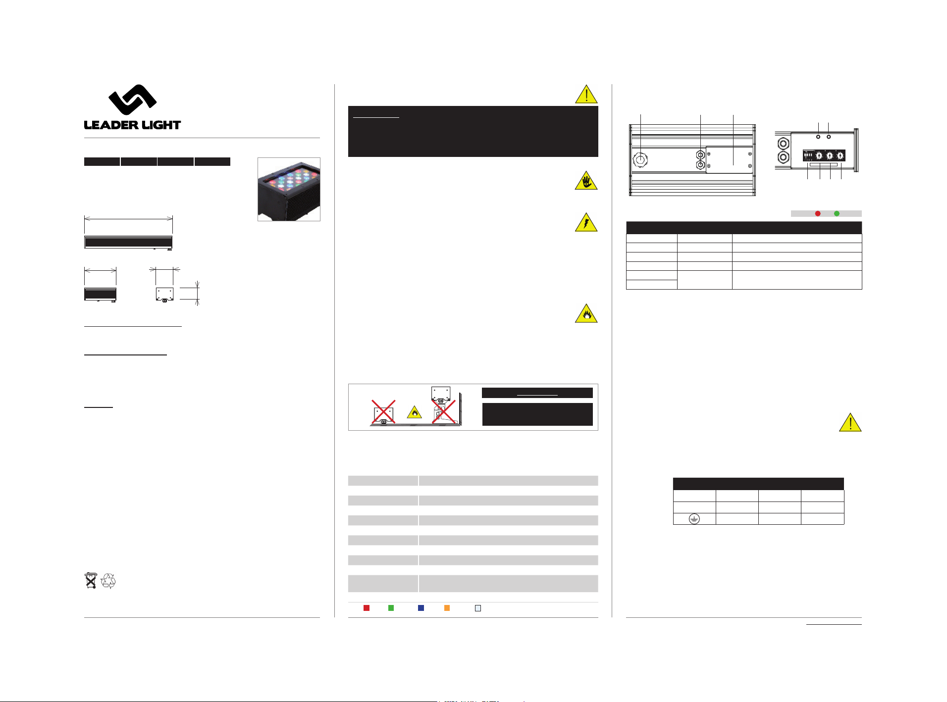
Order code Product name
LL35 070 LL PRO WASH RGBAW 200 FIX 25° ** IP65
LL35 090 LL PRO WASH RGBAW 600 FIX 25° ** IP65
LL35 100 LL PRO WASH AW 200 FIX 25° ** IP65
LL35 120 LL PRO WASH AW 600 FIX 25° ** IP65
Accessories:
LL37 910 LL BARNDOOR PRO WASH 600
** Optional 10°, 40°, EL (Eliptical 15°x90°), AS (Asymetrical) on request.
05 MAINTENANCE
To tackle all Safety Information- 01!
Damage caused by inadequate cleaning or maintenance is not coveredby warranty.
Regular cleaning is demand (dust, dirt, ...).
Maintenance policy:
Unplug mains before maintenance and at least 10 minutes cool off
Appliance do not illegal open or demount
Clean-up dust only from outer surface (for ex. scuttle, diffuser and lenses).
Use vacuum or dumpy duster (warm water)
Before reinstalling to check failure-free state – no wet parts!
-
-
-
-
-
-
-
-
Ch. WASH 600 RGBAW Ch. WASH 600 AW
Mode1: Dip2=Off
1 Red 1,2,3 1 Amber 1,2,3
2 Green 1,2,3 2 White 1,2,3
3Blue 1,2,3 3Master (Dip1=On, Dip4=Off)
4Amber 1,2,3 4 Strobo (Dip1=On, Dip4=Off)
5 White 1,2,3 5
6Master (Dip1=On, Dip4=Off) 6
7Strobo (Dip1=On, Dip4=Off) 7
Mode4: Dip2=On
1 Red 1 1 Amber 1
2 Green 1 2 White 1
3Blue 1 3 Amber 2
4Amber 1 4White 2
5 White 1 5 Amber 3
6 Red 2 6 White 3
7 Green 2 7 Master (Dip1=On, Dip4=Off)
8 Blue 2 8 Strobo (Dip1=On, Dip4=Off)
9Amber 2 9
10 White 2 10
11 Red 3 11
12 Green 3 12
13 Blue 3 13
14 Amber 3 14
15 White 3 15
16 Master (Dip1=On, Dip4=Off) 16
17 Strobo (Dip1=On, Dip4=Off) 17
Extention and control functions:
Dip4=Off, Dip1=Off =>DipBCD: use rotating switch for DMX start
address (RS1-100, RS2-010, RS3-001) from 001 to 511
Dip4=Off, Dip1=On: address+2channel (Master+Strobo)
Dip4=On, Dip1=Off: switch on AutoRun-table functions:
“100“=Prg.0-9, “10“=StepTime, “1“=FadeTime
Dip4=On, Dip1=On: switch all channels on 50% - test
function
Dip2=Off: Mode 1 (5+2ch) Dip2=Off: Mode 1 (2+2ch)
Dip2=On: Mode 4 (15+2ch) Dip2=On: Mode 4 (6+2ch)
Dip3=Off: standard curve
Dip3=On: ultraSoft curve
Adjustable bracket
Mechanical mounting of LL PRO WASH IP65 and Adjustable bracket
2.1 Fit the adjustable bracket on the tting and t with srews.
The installation of LL PRO WASH IP65 and Adjustable bracket is easy.
It is not necessary
to open the xture before the mechanical mounting.
90°
AIMING POSSIBILITY
The xture could be aim
to wish position with the
bracket.
2.2 The bracket x to the solid surface with srews (minimal 4pcs).
1.1
minimal.
100mm
Ventilation space 180° free
Minimal mounting distance from surface
Ventilation space 90° free
INSTALLATION SPACE
minimal.
200mm
minimal.
100mm
minimal.
100mm
WARNING!!!
Non-minimum distance and/or non-use
the original brackets is at your own risk!
!!
Ch. WASH 200 RGBAW
Mode1: Dip1=Off
1 Red 1
2 Green 1
3Blue 1
4Amber 1
5 White 1
Mode2: Dip1=On
1 Red 1
2 Green 1
3Blue 1
4Amber 1
5 White 1
6 Master
7Strobo 1-19Hz
Functions DipBCD (rotating switch RS1 - „100“, RS2 - „10“, RS3 - „1“)
DipBCD = 000 = DMX address 001
DipBCD = 001 - 512 = DMX address 001 - 512
DipBCD = 9xx = AutoTest: Fade-Over RGBAW
DipBCD = 8xx = AutoTest: all channels on 50%
DipBCD = 7xx = AutoTest: all channels on 100%
DipBCD = 6xx = AutoTest: White on 100%
Functions Dip (switch Dip1, Dip2, Dip3, Dip4)
Dip1 = On = add + 2 channels (Master + Strobo)
Dip4 = Off = activation Standard curve
Dip4 = On = activation UltraSoft curve
Dip2 = Off, Dip3 = Off = future
Dip2 = Off, Dip3 = On = future
Dip2 = On, Dip3 = Off = future
Dip2 = On, Dip3 = On = future
04 PERNAMENT USE LIMITATIONS FOR HEATING DISSIPATION
Pernament use limitations for heating dissipation of LL PRO WASH RGBAW body
temperature must be less then 55°C
40°C ambient temperature -20% of total power
30°C ambient temperature -10% of total power
20°C ambient temperature -0% of total power
Black version - 30%
Silver or White version - 50%
Example: Then nal pernament value for BLACK colour and 40°C ambient temperature
= -30% -20% = 56% = max 143 ≥ (R + G + B + W +A) / 5
It‘s mean average of power go inside the xture at DMX signal
Example:
black LL PRO WASH: 180 ≥ (R + G + B + W + A) / 5
Silver or White LL PRO WASH: 128 ≥ (R + G + B + W +A) / 5
Value for R or G or B or W or A is 100% = 256 = 8bit levels *** RED 50% = 128 value,
RED 75% = 192 value
Final information we don’t drop down each colour power with temperature control to
get maximum for each colour under total recomMendations , therefore you need setup
limitations from control desk !!!
-
This manual suits for next models
4
Popular Lantern manuals by other brands

Lighting Technologies
Lighting Technologies HB LED Series manual

Visual Comfort & Co.
Visual Comfort & Co. Bedford Assembly instructions

Sealey
Sealey CP1810 instructions

Honeywell
Honeywell ImperLED E quick start guide

Humanscale
Humanscale Diffrient Work Light II instructions

SLV
SLV HORN 2 GU10 operating manual