CS-D808&CS-D1008ClosedLoopStepperDriveUserManual
Page | 5
DIR- I
counterclockwise). (2). In double-pulse (CW & CCW) control mode, this signal represents
counterclockwise (CCW) rotation. It is active at both voltage high level and low level. (3).
Minimal DIR signal setup time should be at least 5μs. (4). Rotation direction is related to your
motor/drive wiring. You can reverse the default rotation direction by toggling the SW5 DIP
switch.
ENA+ I Enable signal: This signal is used for enabling/disabling the drive. High voltage level of 4.5-24V
(NPN control signal) for enabling the drive and low voltage level of 0-0.5VDC for disabling the
drive. PNP and Differential control signals are on the contrary, namely Low level for enabling.
By default this signal is left UNCONNECTED & ENABLED.
ENA- I
Pend+ O Configurable Digital Output Signal: A configurable OC output signal. It takes a sinking or
sourcing 20mA current at 5-24V. It can to be configured as one of the 2 types, IN POSITION
(default), or BRAKE CONTROL through Leadshine ProTuner CS-D software.
Pend- O
ALM+ O Fault Signal: An OC output signal which is active when one of the following error protection is
activated: over-voltage, over-current, and position following error. This port can sink or source
20mA current at 5-24V. The resistance between ALM+ and ALM- is low impedance in normal
operation, and will change to high when the drive goes into error protection. The voltage active
level of this fault output signal can be configured by configuration software.
ALM- O
Notes: (1) Shielding control signal wires is suggested; (2) to avoid/reduce interference, don’t tie control signal cables
and power wires together.
b) In Position, or Brake control Output Configuration
The digital output on the P2 connector, marked as Pend+ & Pend-, is software configurable (read Leadshine ProTuner
CS-D software manual). It can be configured as one of the available 2 options - “In Position”, and “Brake Control”.
Read Leadshine ProTuner CS-D closed loop software manual for how to configure this output.
In Position
Use Leadshine ProTuner for CS-D software to configure this output as an IN POSITION output. In this case, an
output signal can be sent out when the targeted position is in the “Target” range (see parameter Distance to Send
"In position" Output Signal in software manual) to external devices such as relays, motion controllers, PLCs, IO
boards, etc.
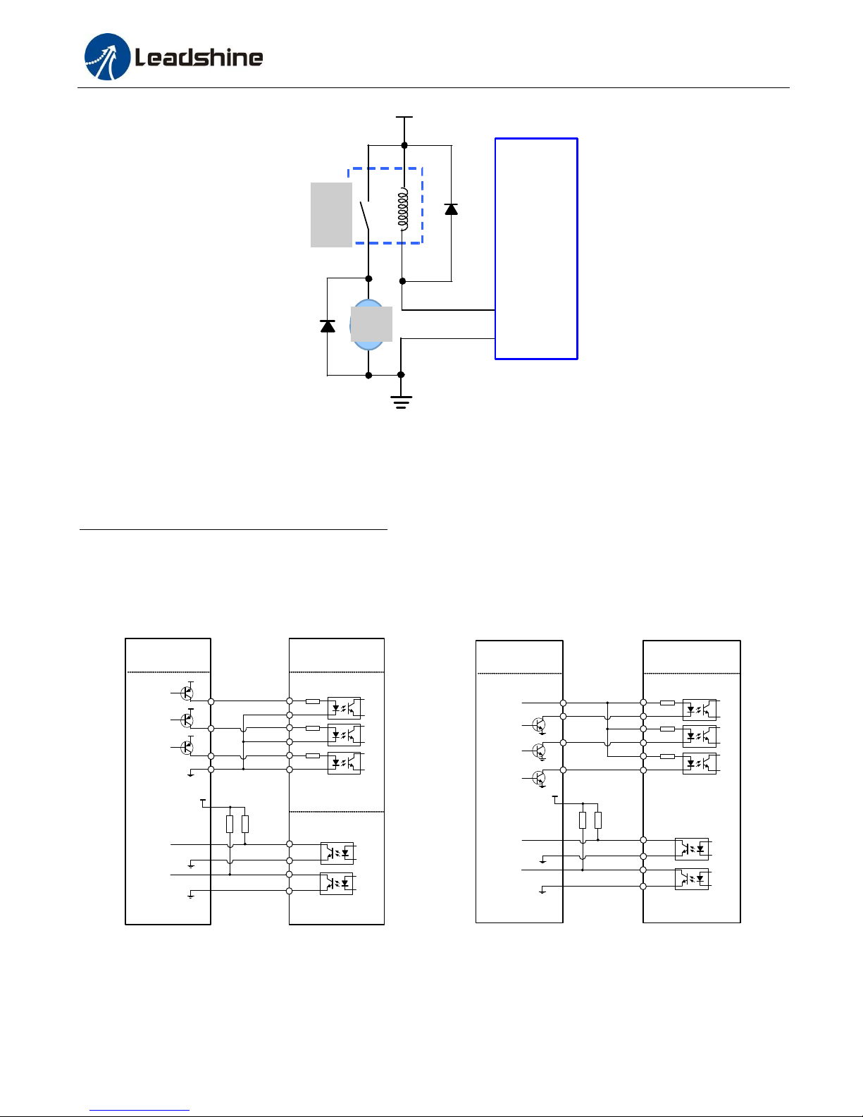
Brake Control
Use Leadshine ProTuner for CS-D software to configure this output as a BRAKE CONTROL output. In this case,
this signal can be used for automatic brake control while system power failure. It is recommended to connect a
fly-wheel diode in parallel to a 24VDC relay and brake coil connection. Refer to the following figure for brake
connection