EM870S Digital Stepper Drive User Manual
Table of Contents
1. Introduction.................................................................................................................................................................. 1
1.1 Features................................................................................................................................................................ 1
1.2 Applications ......................................................................................................................................................... 1
2. Specifications................................................................................................................................................................ 2
2.1 Electrical Specifications ...................................................................................................................................... 2
2.2 Environment ........................................................................................................................................................ 2
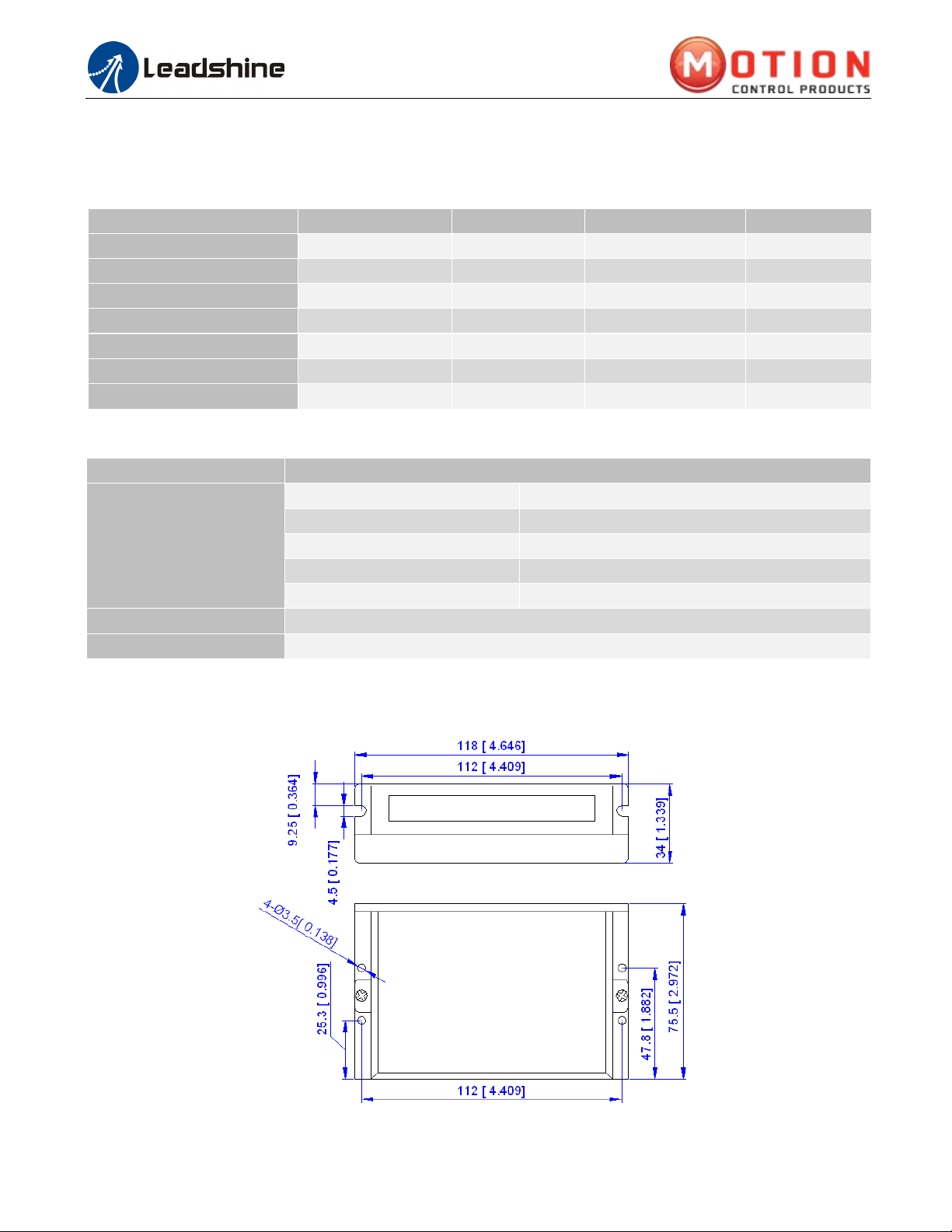
2.3 Mechanical Specifications ................................................................................................................................... 2
2.4 Elimination of Heat.............................................................................................................................................. 3
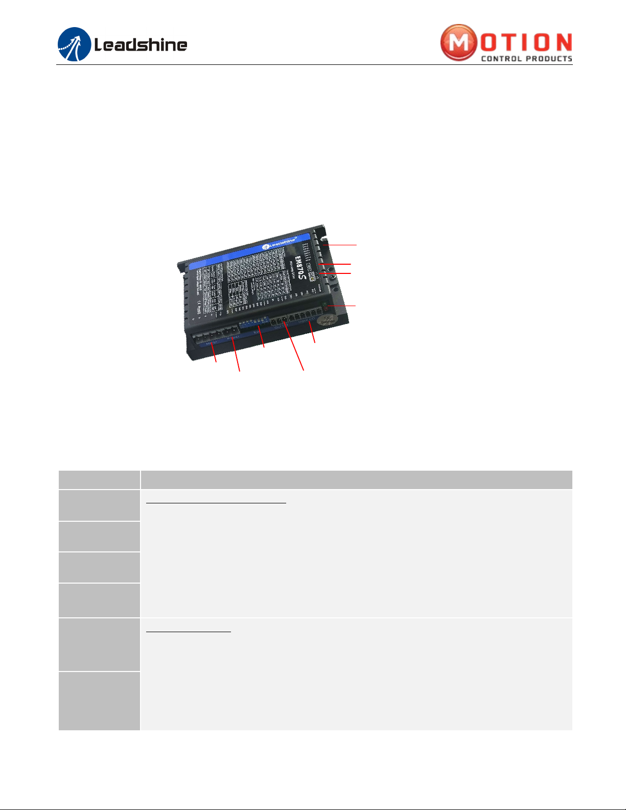
3. Connection Pin Assignments and LED Indication.................................................................................................... 3
3.1 P1 - Control Connector Configurations ............................................................................................................... 3
3.2 P2 - Fault and Brake Output Connector............................................................................................................... 4
3.3 P3 - Power Connector.......................................................................................................................................... 4
3.4 P4 - Motor Connector .......................................................................................................................................... 4
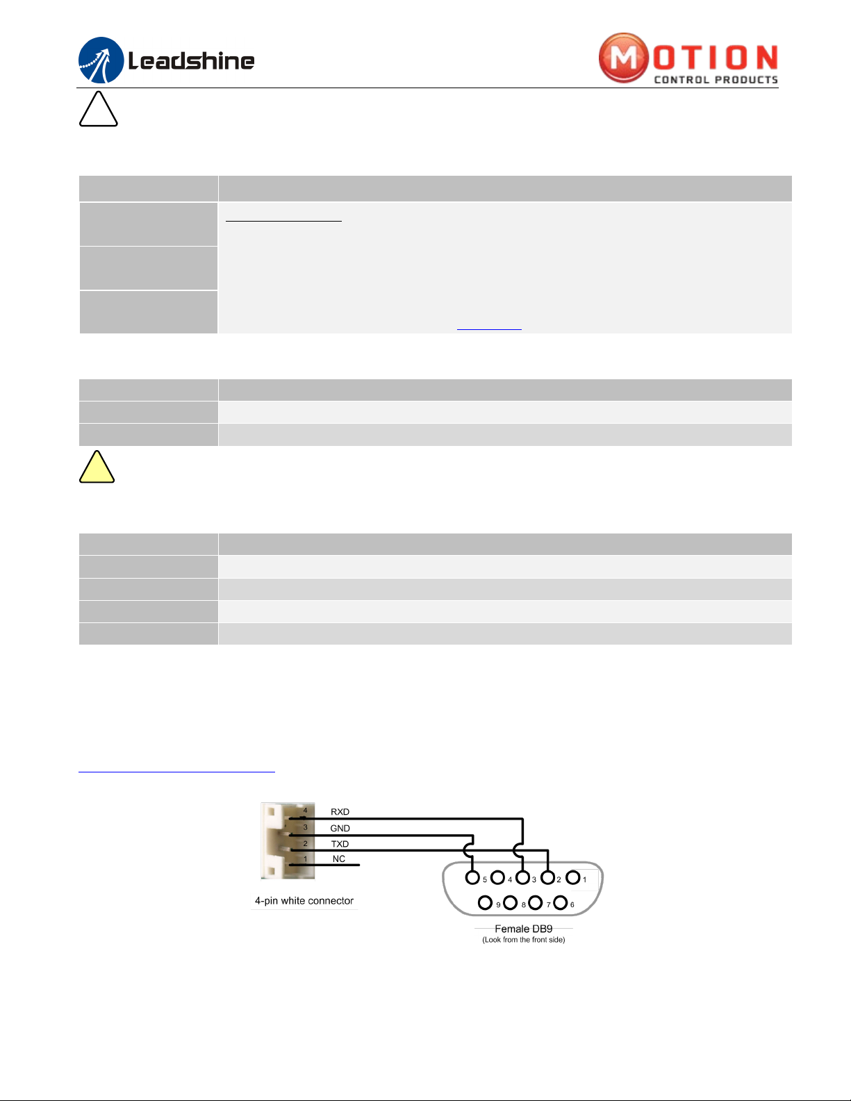
3.5 P5 - Tuning Port................................................................................................................................................... 4
3.6 Status LED Lights................................................................................................................................................ 4
4. Control Signal and Fault Output ............................................................................................................................... 5
4.1 Control Signal Connection .................................................................................................................................. 5
4.2 Fault and Brake Output Connection .................................................................................................................... 5
5. Stepper Motor Connections ........................................................................................................................................ 6
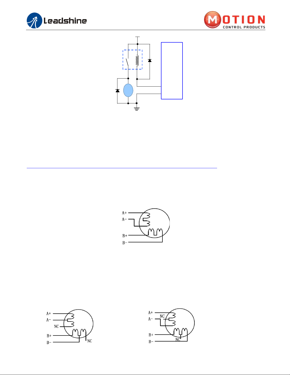
5.1 4-lead Motor Connection (recommended)........................................................................................................... 6
5.2 6-lead Motor Connection..................................................................................................................................... 6
5.3 8-lead Motor Connection..................................................................................................................................... 7
6.Power Supply Selection ................................................................................................................................................ 7
6.1 Regulated or Unregulated Power Supply............................................................................................................. 7
6.2 Power Supply Sharing ......................................................................................................................................... 8
6.3 Selecting Supply Voltage ..................................................................................................................................... 8
7.DIP Switch Configurations .......................................................................................................................................... 8
7.1 Output Current Configuration (SW1-3) ................................................................................................ 8
7.2 Idle Current Configuration (SW4) ................................................................................................ 9
7.3 Micro Step Configuration (SW5-8) ................................................................................................ 9
7.4 Smoothing Filter Time Configuration (SW9-10)............................................................................................... 10
7.5 No Auto Tuning Configuration (SW11)....................................................................................... 10
7.6 Alarm Output Configuration (SW12) .............................................................................................. 10
7.7 Activated Pulse Edge Configuration (SW13) .................................................................................................... 10
7.8 Control Mode Configuration (SW14)................................................................................................................ 10
7.9 Shaft Lock Configuration (SW15)..................................................................................................................... 10
7.10 Self-Test Configuration (SW16)...................................................................................................... 10
8. Wiring Notes................................................................................................................................................................11
9. Typical Connection .....................................................................................................................................................11
10. Sequence Chart of Control Signals .........................................................................................................................11
11. Protection Functions................................................................................................................................................ 12
12. Troubleshooting ....................................................................................................................................................... 13
13. Warranty .................................................................................................................................................................. 14