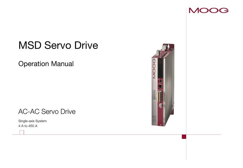
MSDServoDrive AC-AC Operation Manual
moog 7
Id. no.:CA65642-001 Date:03/2012
to the glossary
Table of Contents
1 Safety...................................................................................... 9
1.1 Measures for your safety.........................................................................................9
1.2 Intended use...........................................................................................................10
1.3 Responsibility ..........................................................................................................10
2 Mechanical installation............................................................11
2.1 Notes on installation ...............................................................................................11
2.2 Installation ..............................................................................................................11
2.2.1 Dimensions on devices with air cooling........................................................12
2.2.2 Dimensions on devices with liquid cooling ...................................................14
2.2.3 Connection of cooling circuit.......................................................................16
3 Installation............................................................................. 17
3.1 Notes for installation...............................................................................................17
3.2 Overview of connections Size1 to Size4 ................................................................18
3.3 Overview of connections Size5 to Size6A..............................................................20
3.4 Overview of connections Size7 ..............................................................................22
3.5 Connection PE conductor .......................................................................................24
3.6 Electrical isolation concept......................................................................................24
3.7 Connection of supply voltages ................................................................................26
3.7.1 Connection control supply (24VDC)...........................................................26
3.7.2 Connection of AC mains supply...................................................................27
3.7.3 Use with mains choke..................................................................................30
3.7.4 Use with internal mains filter .......................................................................30
3.7.5 Use with external mains filter.......................................................................30
3.7.6 Terminal diagram precharge (only Size7).....................................................30
3.8 Control connections................................................................................................31
3.8.1 Specification of control connections ............................................................31
3.8.2 Brake driver .................................................................................................32
3.9 Specification USB interface .....................................................................................33
3.10 Specification Ethernet interface...............................................................................33
3.11 Option 1 .................................................................................................................33
3.12 Option 2 .................................................................................................................34
3.13 Encoder connection ................................................................................................34
3.13.1 Encoder connection on servo motors...........................................................34
3.13.2 Assignment of motor/encoder cable to servo drive ......................................34
3.13.3 Ready made-up encoder cables ...................................................................35
3.13.4 Resolver connection.....................................................................................35
3.13.5 Connection for high resolution encoders.....................................................36
3.14 Motor connection...................................................................................................37
3.14.1 Motor connection on servo motors .............................................................37
3.14.2 Ready made-up motor cable........................................................................38
3.14.3 Switching in the motor cable .......................................................................39
3.15 Braking resistor (RB) ................................................................................................39
3.15.1 Protection in case of a brake chopper fault..................................................39
3.15.2 Design with integrated braking resistor Size1 - Size 4 .................................40
3.15.3 Design with integrated braking resistor Size5 - Size 7 .................................41
3.15.4 Connection of an external braking resistor ..................................................41
4 Commissioning ...................................................................... 43
4.1 Notes for operation.................................................................................................43
4.2 Initial commissioning...............................................................................................43
4.2.1 Switching on control supply.........................................................................44
4.2.2 Connection between PC and servo drive .....................................................44
4.2.3 Parameter setting ........................................................................................44
4.2.4 Drive control with MoogDriveADministrAtor5 ..............................................44


