15 16
Front direction
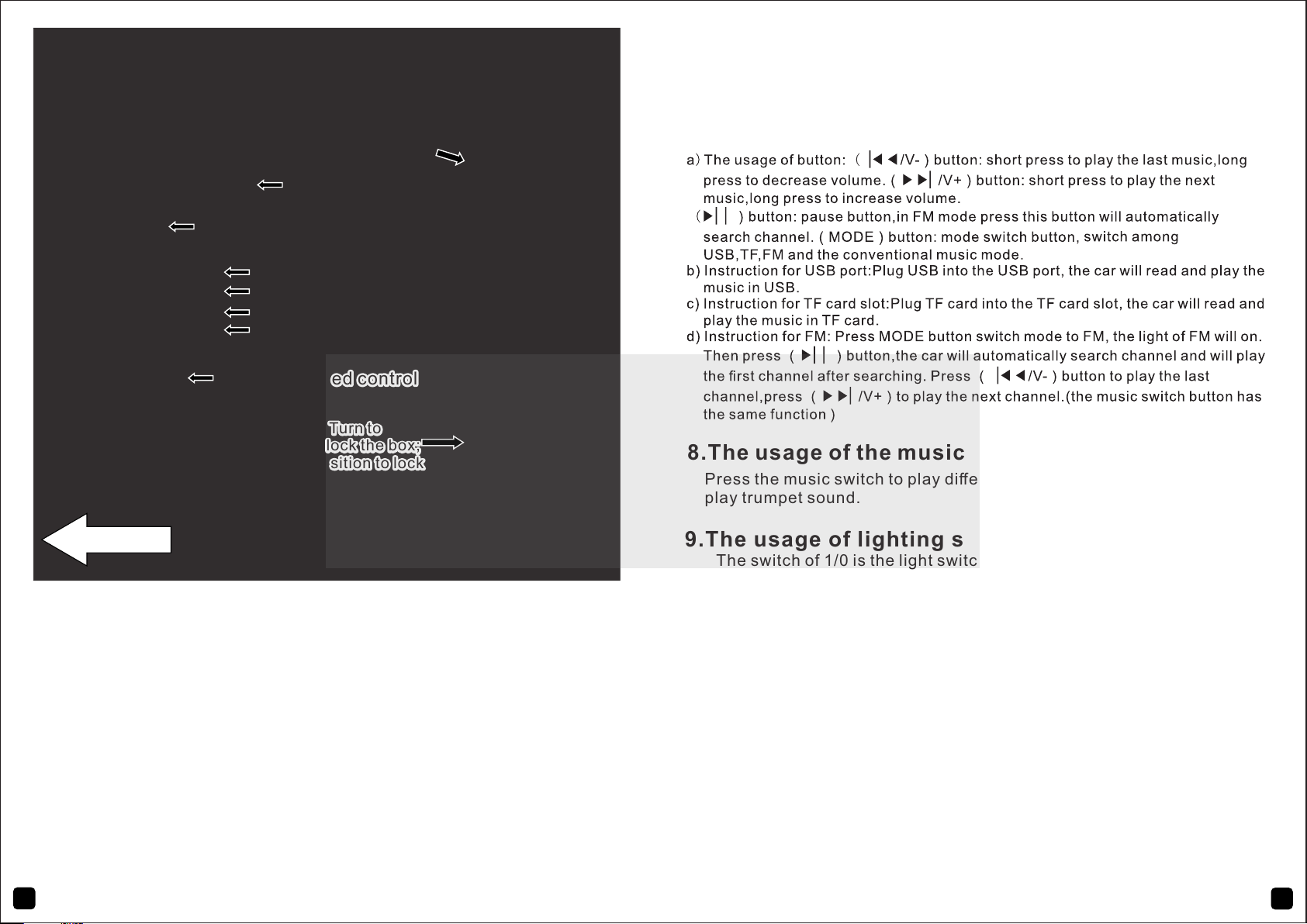
tail box unlock switch R (Turn to anti -
clockwise position to unlock the box;
turn to clockwise position to lock the
box)
tail box unlock switch R (Turn to anti -
clockwise position to unlock the box;
turn to clockwise position to lock the
box)
foot switch (accelerator)foot switch (accelerator)
Forward/Backward switchForward/Backward switch
horn button horn button
music switchmusic switch
power switchpower switch
light switchlight switch
high-low speed controlhigh-low speed control
tail box unlock switch L (Turn to
clockwise position to unlock the box;
turn to anti-clockwise position to lock
the box)
tail box unlock switch L (Turn to
clockwise position to unlock the box;
turn to anti-clockwise position to lock
the box)
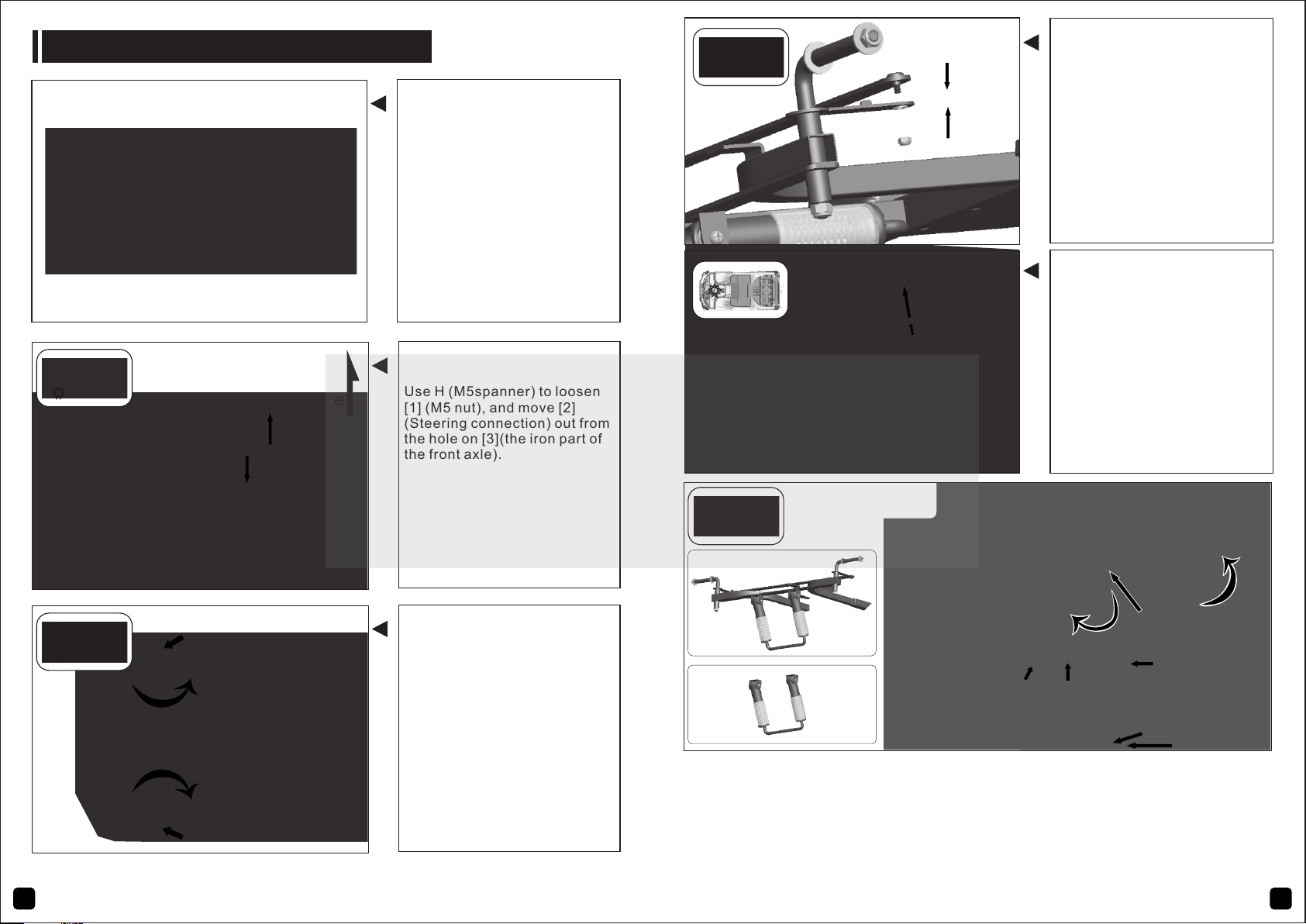
5.Operation guide for Manual control (forward,
backward and speed control):
After the driver is seated, press the power switch, the car will send out a
starting sound (2-5seconds). Put the Forward/Stop/Backward switch into
the position of “forward” (Press forward), the hi/lo speed switch into the
position of “low speed”, step on the foot switch the car will move forward
slowly, loosen the pedal the car will stop. Put the hi/lo speed switch into the
position of “high speed”, step on the foot switch the car will move forward
fast, loosen the pedal the car will stop. Put the Forward/Stop/Backward
switch into the position of “Backward”, step on the foot switch the car will
move backward fast, loosen the pedal the car will stop. Put the hi/lo speed
switch into the position of “low speed”, step on the foot switch the car will
move backward slowly, loosen the pedal the car will stop. Put the
Forward/Stop/Backward switch into the position of “stop”, the car can not
move forward and backward.
9.The usage of lighting switch
The switch of 1/0 is the light switch, turn the switch to “1” the lights on,
turn the switch to “0” the lights off.
7.Instruction for MP3 multifunction player
6.Remote control in change direction:
Press Steer Left, the car will turn left; press steer right, the car will turn
right.
8.The usage of the music switch and the horn button
Press the music switch to play different music. Press the horn button to
play trumpet sound.