7
Wall Bracket Assembly
•IMPORTANT: Obtain professional
advice and have a qualified person
install the brackets to ensure
adequate support.
•IMPORTANT: Do not fasten the
brackets to a drywall surface or to a
cinder block surface.
•The location on the wall to which the
brackets are fastened must be capable
of supporting a working load of 600 lbs.
(272 kg). IMPORTANT: The brackets
and the weight rack should not be
used by persons weighing more than
300 lbs. (136 kg).
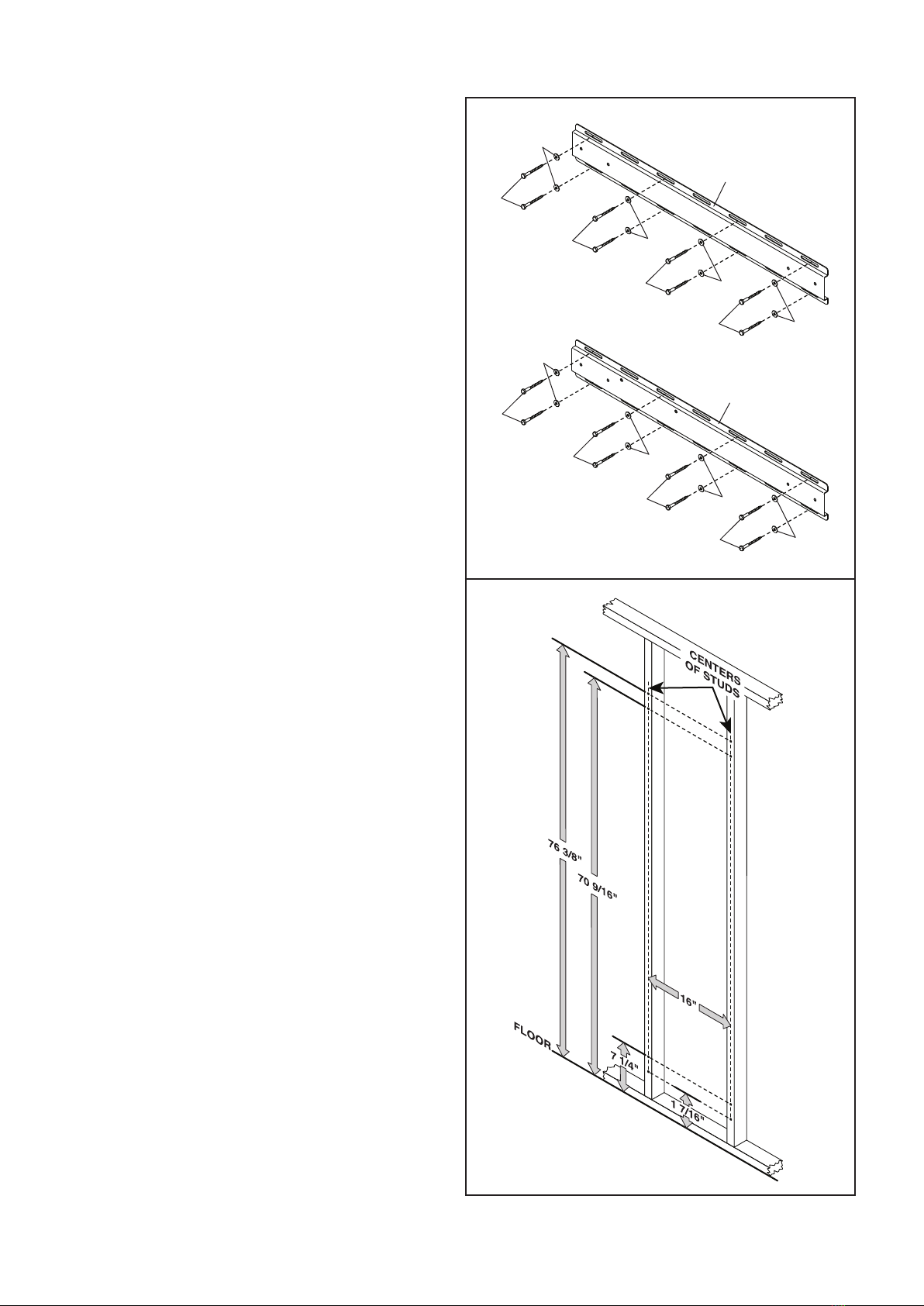
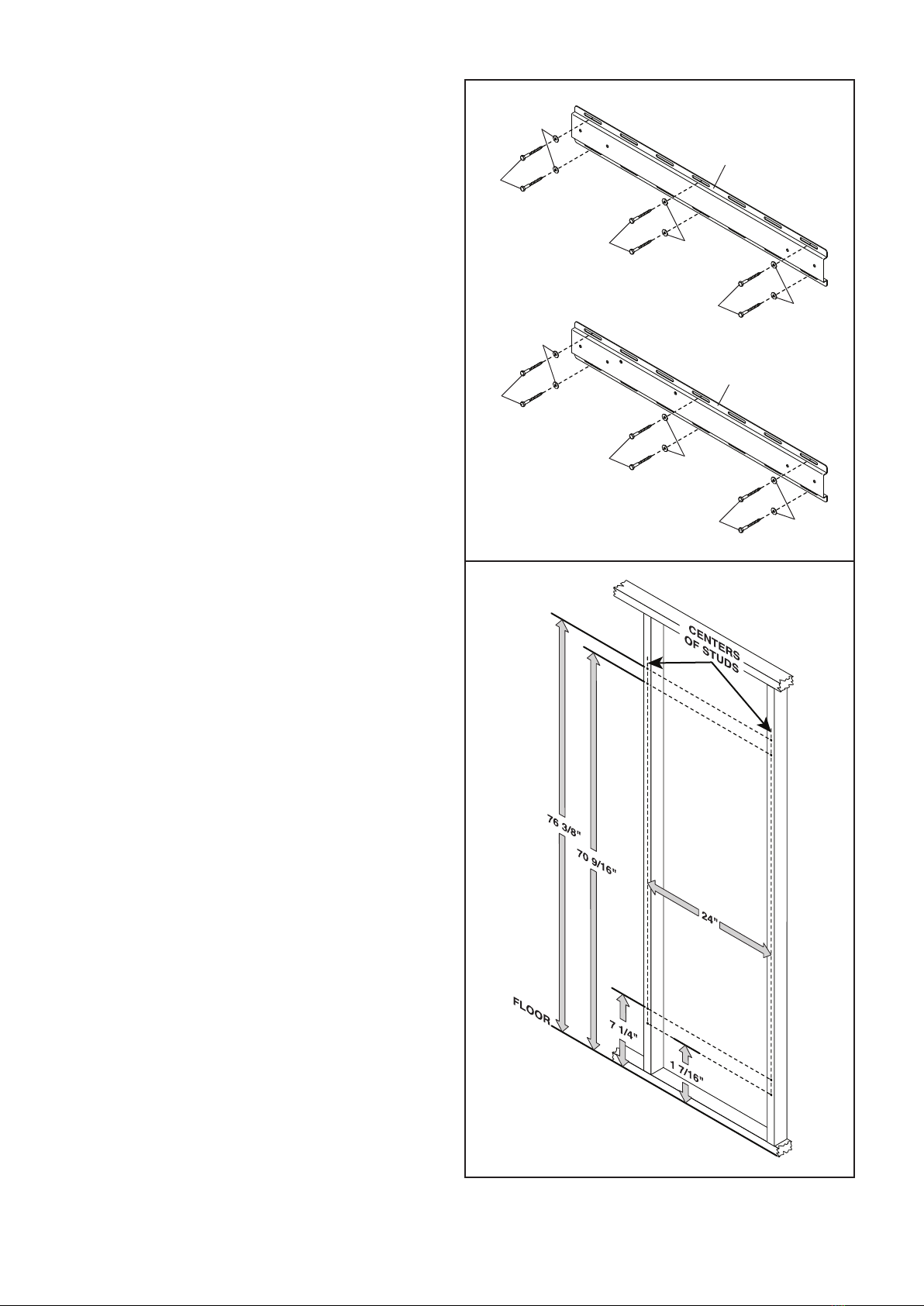
•The brackets must be securely fas-
tened to the centers of wood or metal
wall studs in a wall that is at least 8 ft.
(244 cm) high, above a flatsurface that
is at least 6 ft. (183 cm) long and 6 ft.
(183 cm) wide. This placement provides
sufficient space to use the weight rack
effectively.
•Taking your height into consideration,
make sure that there will be adequate
clearance between the weight rack and
the ceiling to perform the exercises that
you wish to perform with the weight rack.
•The upper bracket. The upper slots in
the bracket must be positioned 76 3/8 in.
(194 cm) above the floor. The slots in the
bracket can be positioned over wall studs
that are spaced 16–24 in. (41–61 cm)
apart.
•The lower bracket. The lower slots in
the bracket must be positioned 1 7/16 in.
(4 cm) above the floor The slots in the
bracket can be positioned over wall studs
that are spaced 16–24 in. (41–61 cm)
apart.
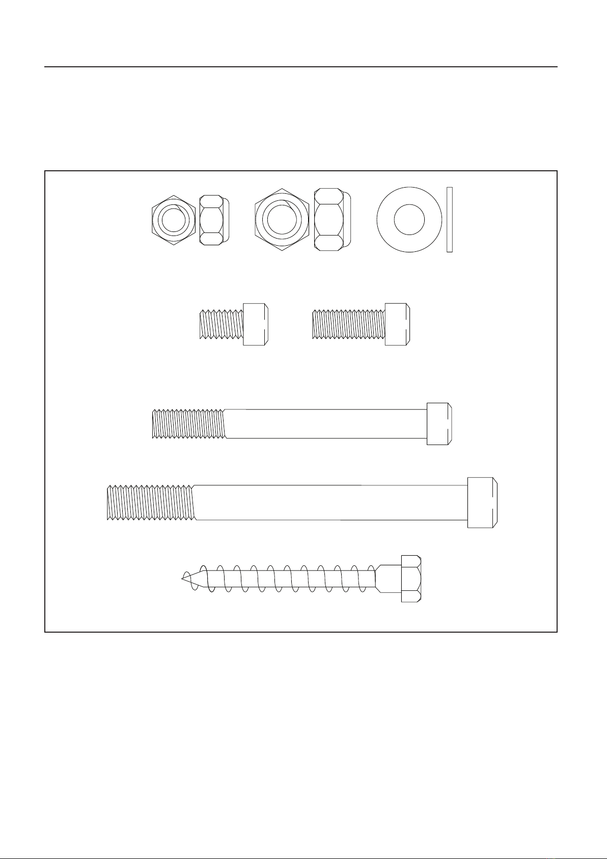
•If you are fastening the brackets to
metal wall studs, you will need six-
teen M10 x 100mm toggle bolts (not
included). Follow the manufacturer’s
instructions to install the M10 x 100mm
toggle bolts in metal wall studs.
•If you are fastening the brackets to a concrete
surface, you will need sixteen 3/8" lag screws
(not included) designed for use with sixteen
concrete lag anchors (not included). Follow the
manufacturer’s instructions to install the 3/8" lag
screws and the concrete lag anchors.